STEP 1
Loosen the 3 hose clamps that are attached to the long upper intake tube.
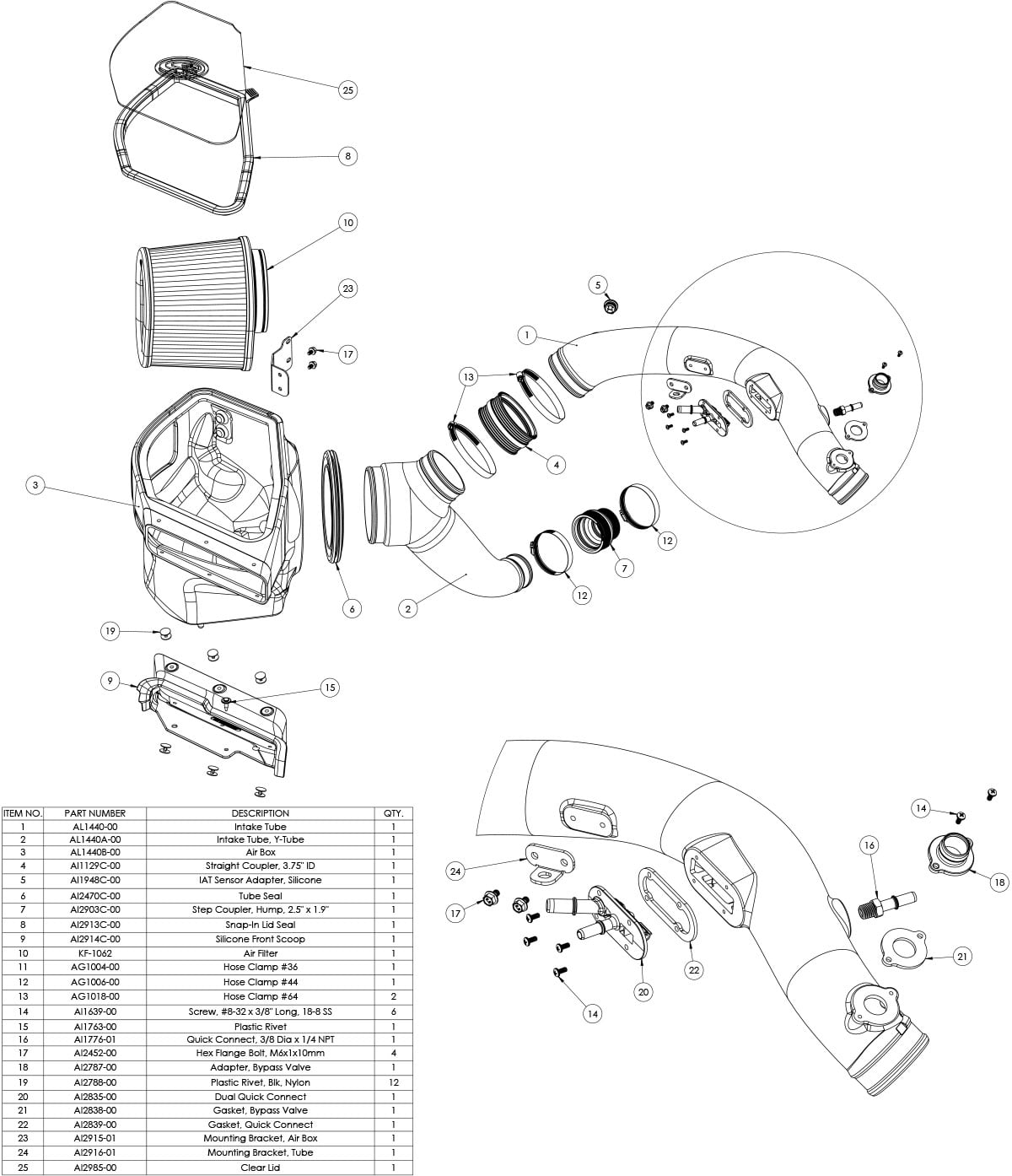
Please read the entire product guide before proceeding.
Ensure all parts are present.
If you are missing any of the components, call our customer support at (909) 947-0015.
Do not work on your vehicle while the engine is hot.
Make sure the engine is turned off and the vehicle is in Park and the Parking Brake is set.
S&B FILTERS recommends that you keep your OE intake system in the event it is required in the future.
In order to maintain your warranty, all connections and components must be checked periodically for alignment and for proper tension on all connections. Failure to do so may void your warranty.
Use only S&B FILTERS cleaning and oil products to service your filter. Using any other brand oil and or cleaners on your S&B air filter may void your warranty
• Intake Tube (11) and Filter (7) connections and Intake Box (1) fasteners making sure they are tight.
• All electrical connections and wire harnesses moved during the installation of the intake and make sure they are secure and away from any hot or moving components.
• Check for any signs of abrasion or wear and tear on the intake tube, box, filter, and electrical harnesses moved or near the intake and repair/replace as necessary.
7mm, 8mm, and 10mm, Socket and ¼” Drive Wrench
7mm Deep Socket
3” Socket Extension
6” Socket Extension or 3” + 3” Socket Extensions
3/4” Open/Box Combination Wrench
5/16” Nut Driver
Panel Popper
Phillips Screwdriver
Wire Cutters
Adjustable Pliers
Note: Approximate Install Time: 1 Hr
Loosen the 3 hose clamps that are attached to the long upper intake tube.


Disconnect the 3 quick connect fittings.

Remove the screw shown in the picture with a 5/16 nut driver or socket.

Disconnect the IAT sensor harness.

Disconnect the hose from the stock intake tube by squeezing the clamp.

Remove the stock intake tube from the vehicle.

Remove the push rivet that is securing down the front inlet then remove the intake from the vehicle.

Squeeze the constant tension band clamp to remove the intake tube connected to the lower turbo.

Install the dual quick connect fitting and gasket on the S&B intake tube then tighten down with the provided hardware.

Install the gasket then the plastic bypass valve adaptor onto the tube.

Install the IAT sensor grommet onto the S&B tube, make sure the tab lines up with the notch on the tube.

Install the IAT sensor onto the S&B tube, make sure the tab backs up against the ramp as shown in the picture.

Install the bracket onto the tube then tighten down.

Install the tube seal onto the S&B airbox.

Install the bracket onto the S&B airbox, then tighten down with the provided hardware.

Install the silicone scoop seal using the provided push rivets.

Install the quick connect fitting onto the S&B tube.

Remove the two bolts shown in the picture. Put them aside because we will use them later.

Drop in the S&B airbox then secure it down using the bolts you just removed.


Install the S&B air filter into the airbox.

Install the S&B silicone scoop with the two push rivets. In order to install the rivet on the right, you will need to expand the hole by drilling through it as seen in our install video.
(Section 7:55-8:15) https://youtu.be/stfnkucrhas

Loosely install the clamps onto the coupler then install the coupler onto the turbo. Once it's on, tighten down the back hose clamp only.

Install the shorter S&B intake tube into the vehicle. Then tighten down the hose clamp at the turbo and air filter.

Install the other S&B intake tube into the vehicle. Then tighten down the hose clamps.

Remove the 90 degree fitting that is on the stock intake tube, then install it onto the S&B intake tube in order to connect the hose.


Slide the clamp back over and clamp down to tighten.

Reinstall the bolt you removed earlier.

Reconnect the 3 quick connect fittings and the IAT sensor.

Remove the protective covering over the Clear Lid and then insert the Lid into the Lid Seal. Then install the Lid Seal with Lid onto the top opening of the Box. Start with one corner of the Box and work your way around until the Lid Seal with Lid is fully snapped into the Box opening.

Inspect your installation, make sure the kit is properly positioned and all fasteners and hose clamps are secured. Keep all stock parts in case you would ever need to reinstall the stock intake assembly. If you are an installer, give the owner the QR code for the Installation Instructions so that he/she is aware of the "Periodically Check the Following" procedures given in the beginning of the Instructions. The Installation is now complete.
