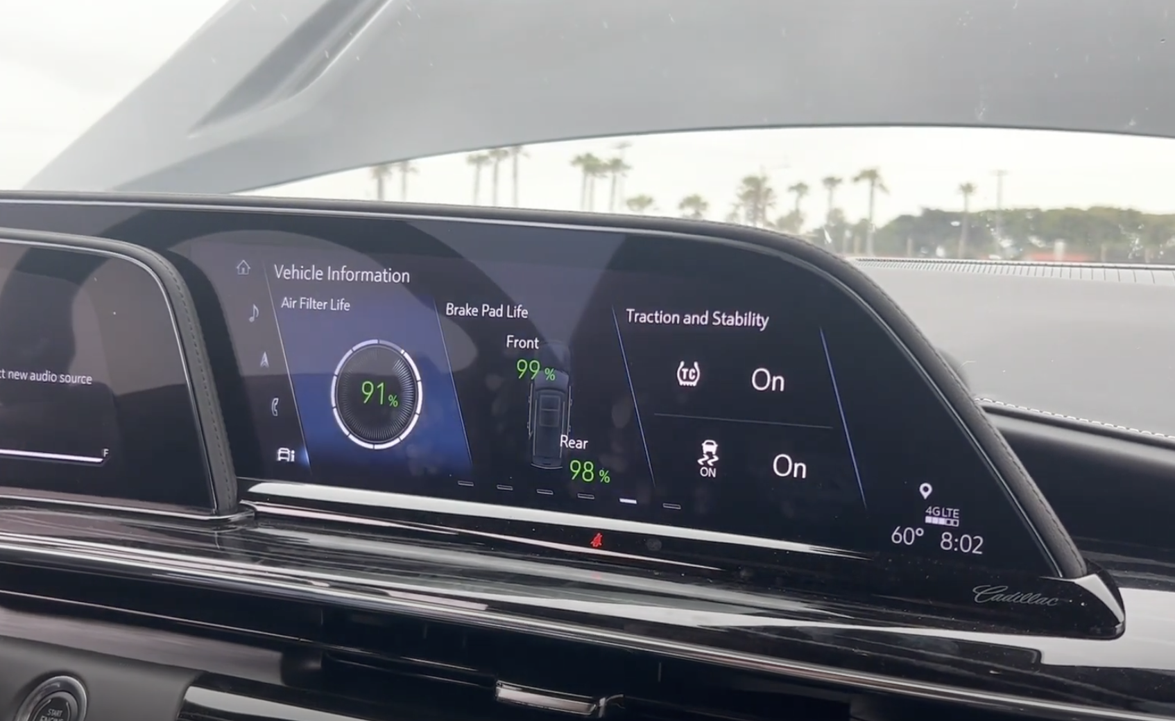
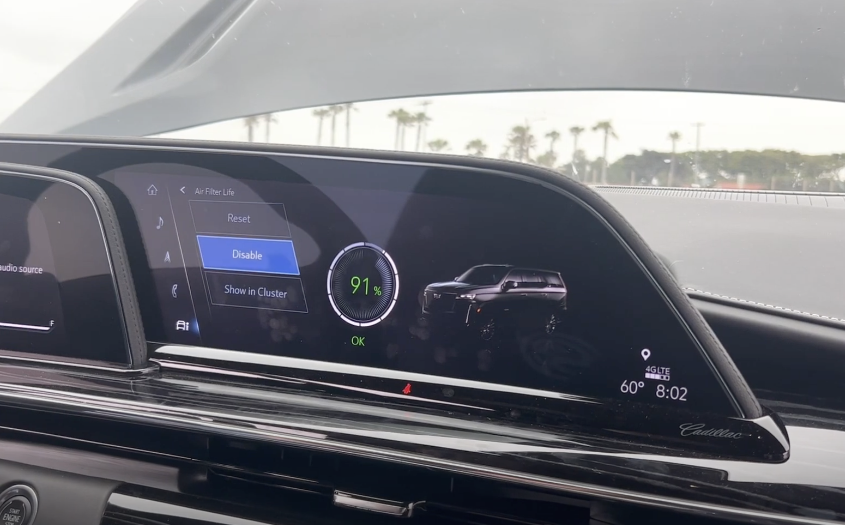
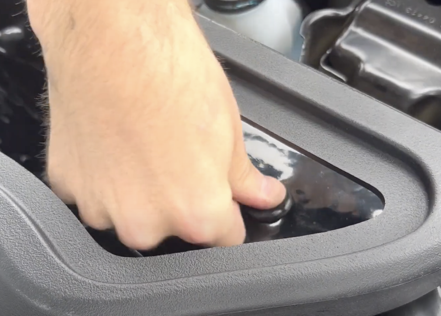
Install Instructions for 75-5173

Before You Start

Note:
This intake kit may not fit with the following Aftermarket Parts installed:
Body Lift or Lowering Kit
Custom Hood

Please read the entire product guide before proceeding. Ensure all parts are present. If you are missing any of the components, call our customer support at (909) 947-0015. Do not work on your vehicle while the engine is hot. Make sure the engine is turned off and the vehicle is in Park or the Parking Brake is set.

Required Tools

7mm, 10mm, 13mm Wrench, 5/16” Nut Driver or Flat Blade Screwdriver, Pin Removal Tool or Flat Blade Screwdriver, T15, T20 Torx Bit,  Phillips Screwdriver, 5/32” or 4mm Allen Wrench, 1 Pair of Pliers or similar tool, Topside Engine Creeper recommended.

Note: Approximate Install Time: 2 Hr 00 Mins.

STEP 1

To start, disable the "air filter life" by hitting the "information" button next to the stick shift. Toggle all the way to the right until you see "air filter life" press it then hit "disable". Once the air filter life is disabled, turn off the vehicle.  

STEP 1(IMAGE 2)

STEP 2

Remove the push clips holding down the large shroud. Remove the shroud and set it aside.

Tool Needed: Panel removal tool or similar.

STEP 3

Remove the push pin that is holding down the front scoop. Then, pop up the front scoop but don't remove it. 

STEP 4

Remove the bolt holding down the front coolant tank.

Tool Needed: 10mm

STEP 5

Carefully disconnect the large wire harness at the front of the air intake. The snap feature is designed to release under sufficient upward force, however, pulling upward while tilting the harness toward the rear of the vehicle will help disconnect the harness.

STEP 6

Disconnect the MAF Harness. Pull back on the red tab to unlock the connector. Press down on the black tab directly under the red tab and pull rearward to disconnect the connector. Then loosen the hose clamps on either end of the stock flexible coupler, the coupler can now be removed from between the stock intake tube and the stock air box.

STEP 7

Loosen the nut with a captive washer holding down the stock air box. Set aside the nut for reuse.

Tool Needed: 10mm wrench or socket.

STEP 8

Remove the stock air box by lifting the front high enough to clear the stud, and pulling the airbox forward, sliding the rear facing prongs out of the bracket.

STEP 9

Find the S&B Air Intake Box and the Silicone Inlet Seal. Then install the Inlet Seal onto the Air Box.

STEP 10

Install the Panel Grommet into the Air Box Mounting Bracket. Install the Machined Aluminum Shoulder Washer into the Panel Grommet. Install the Air Box Mounting Bracket with the ¼ x 20 Button Head Cap Screws. 

Tool Needed: 5/32” or 4mm Hex Key.

STEP 11

Attach the Harness Bracket onto the airbox with the ¼ x 20 Button Head Cap Screw. 

Tool Needed: 5/32” or 4mm Hex Key.

STEP 12

Install the Mounting Prong Grommets onto the rear prongs on the Air Box.

STEP 13

If desired, install the Silicone Box Plug into the side of the airbox. The plug is designed to be able to be inserted from either the interior or exterior of the box; install according to preference.

STEP 14

Install the Airbox into the vehicle, sliding the prongs into their holes and lowering the box onto the stud. Loosely Reinstall the nut with a captive washer onto the stud.

STEP 15

While the box is still loose, push the OEM scoop into the air box inlet. Then reinstall the push rivet and tighten down the captive washer. 

STEP 16

Install this plug into the top of the airbox.  

STEP 17

Grab the fuse box and adjust it to fit next to the airbox. 

STEP 18

Reinstall the bolt to the coolant tank.

STEP 19

Transfer the MAF sensor from the stock airbox to the S&B tube. To do this, lay the MAF pad down on the S&B tube, then lay the injection molded MAF pad on top. Then slide the other piece into the tube and tighten down everything with the included S&B bolts.  

STEP 19 (IMAGE 2)

STEP 20

Snap in the S&B filter into the airbox with the hose clamp loosely attached.

STEP 21

Install the smaller S&B tube into the vehicle with the hose clamps attached.  

STEP 22

Install the other S&B tube into the filter and connect it to the smaller S&B tube. Please use the indictors to align the tubes. 

STEP 22 (IMAGE 2)

STEP 23

Tighten down all the hose clamps that are on the tubes and make sure they are tight.  

STEP 24

Find the S&B clear lid, remove the film and then install the lid into the lid seal.

STEP 25

Install the S&B clear lid into the airbox. 

STEP 26

Reinstall the OEM shroud and reinstall all the push pins. 

STEP 27

Connect the MAF sensor into the MAF harness.