STEP 1
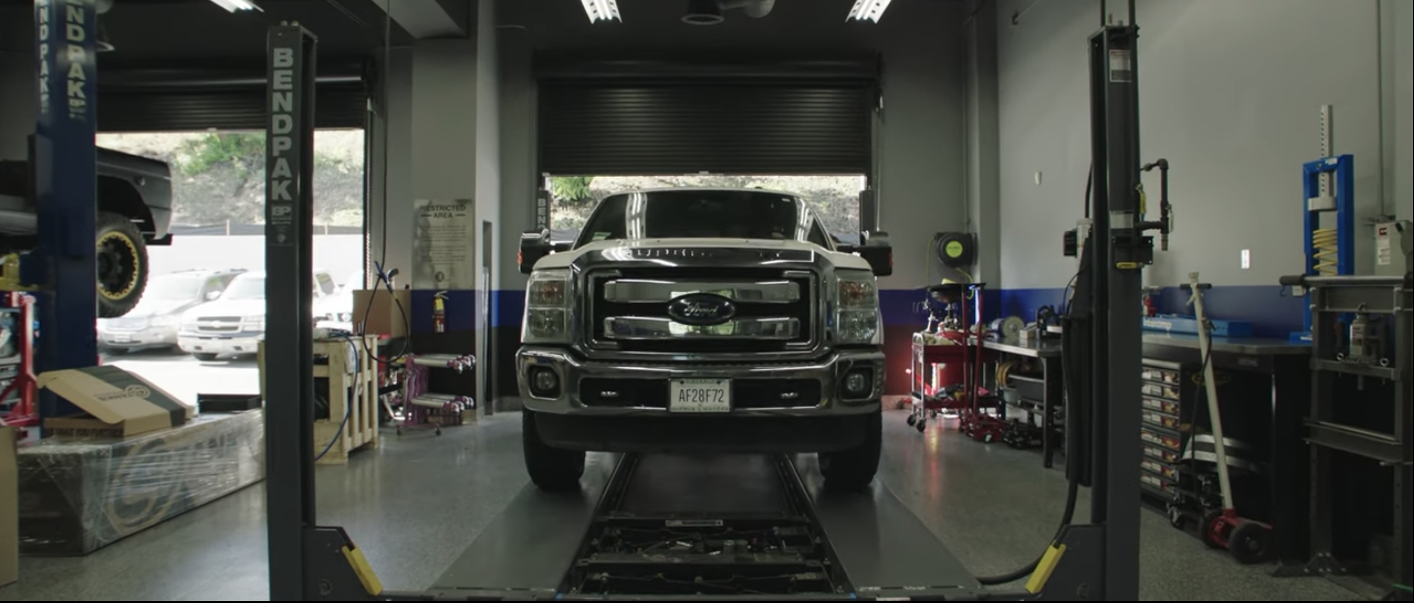
Raise the vehicle up on a lift to working height.
Installation can be completed without a lift. Make sure the vehicle is safely parked with the parking brake set.
.png?v=1767373015843)
Raise the vehicle up on a lift to working height.
Installation can be completed without a lift. Make sure the vehicle is safely parked with the parking brake set.
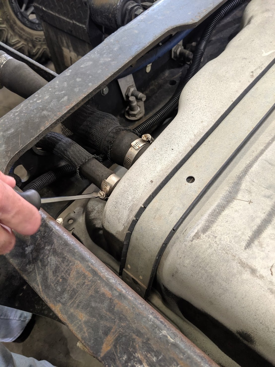
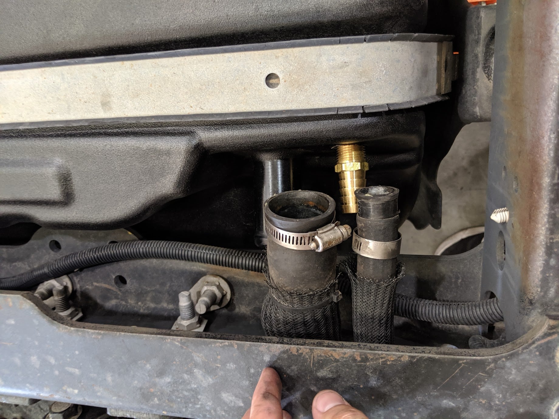
Disconnect the vent and fill hose from the filler/vent neck assembly.
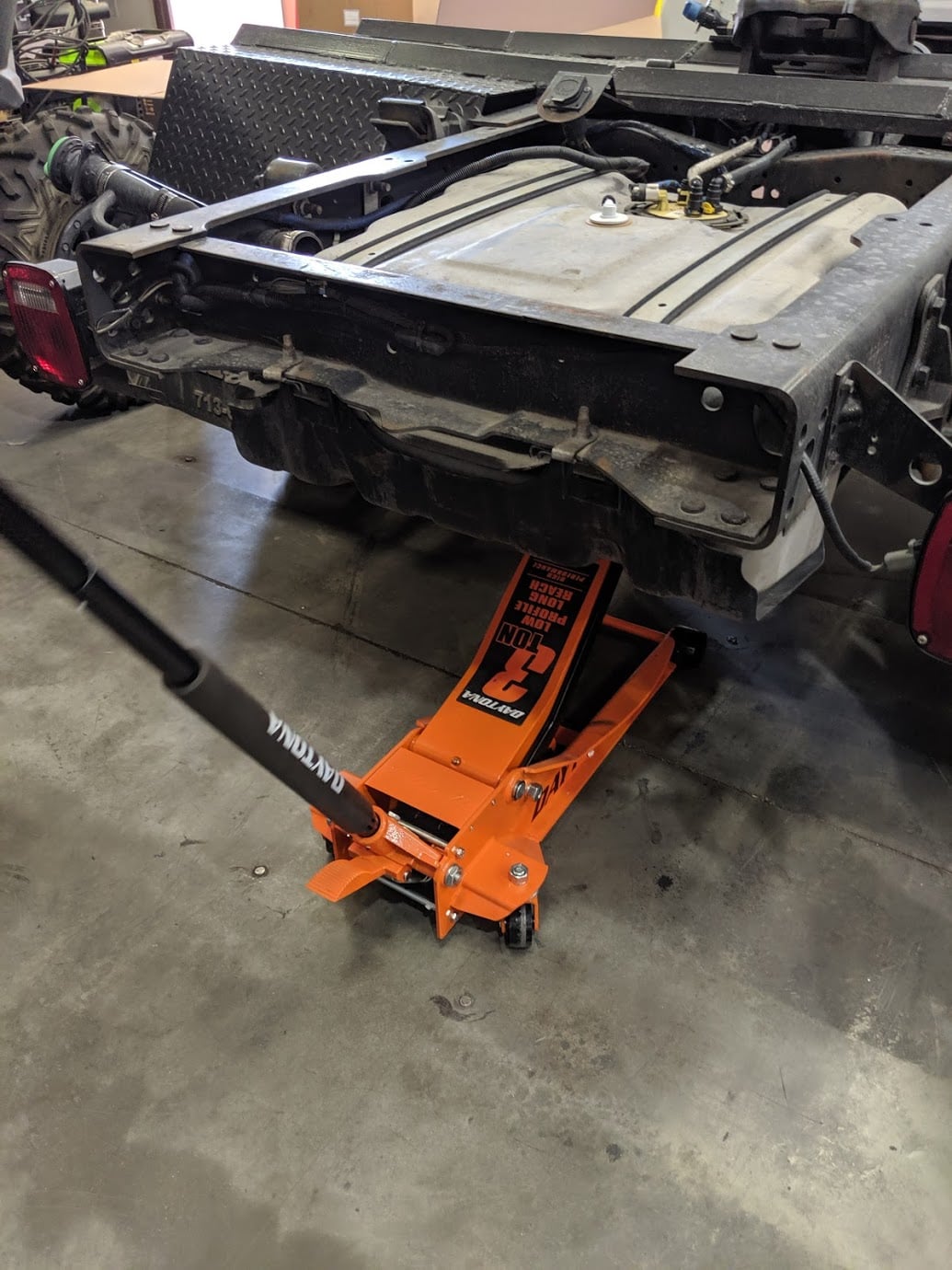
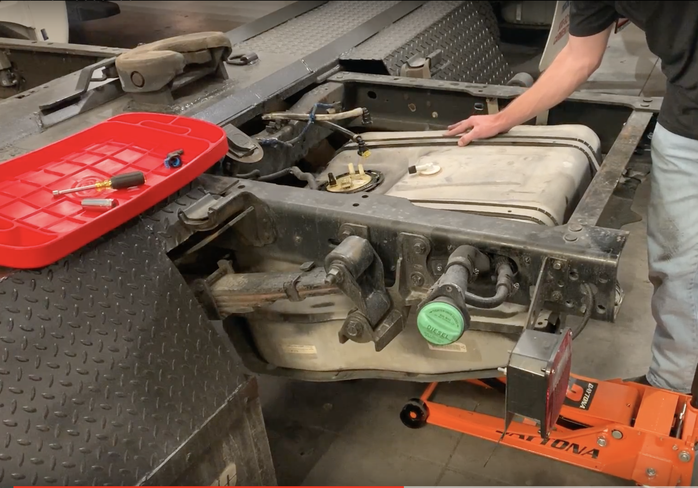
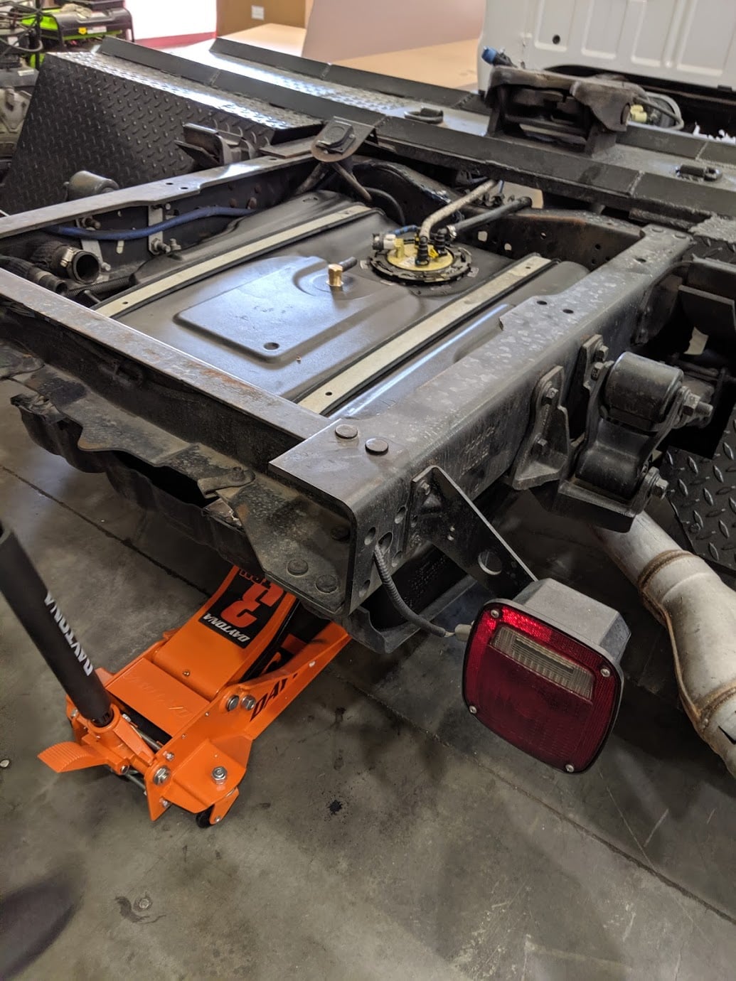
Center the hydraulic jack underneath the fuel tank and raise until the jack contacts the tank. Caution: Support the tank properly as remaining fuel can slosh and cause the tank to shift.
- Lift Install: Hydraulic Jack
-Floor Install: Floor jack with added support to properly hold tank
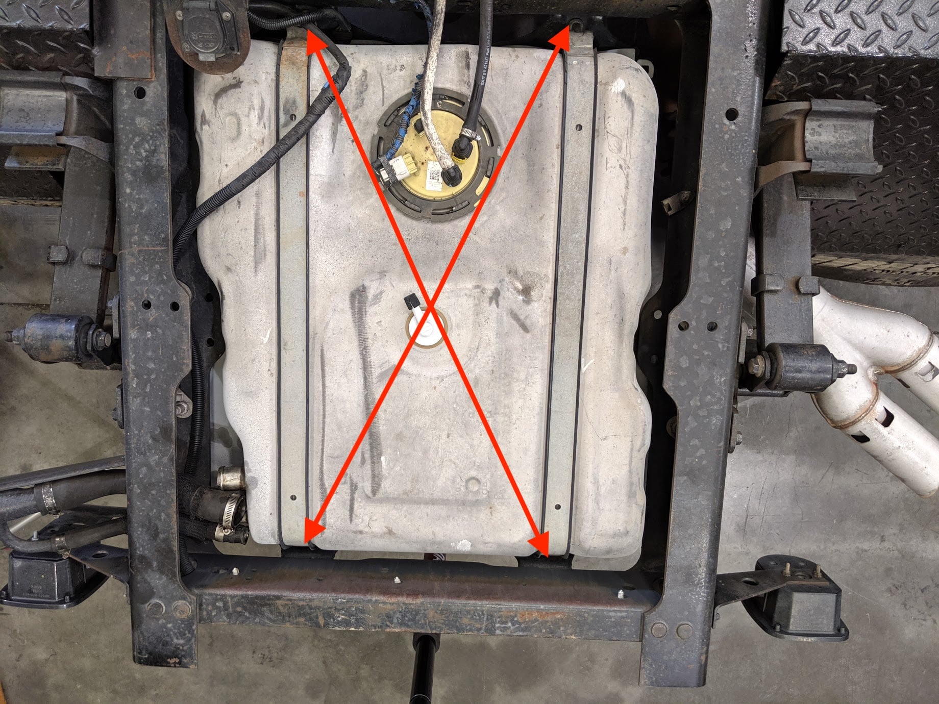
Remove the 4 bolts that fasten the skid plate to the frame. Make sure you only remove the 15mm that hold the skid plate to the frame. You will also see two 19mm bolts that hold the fuel tank in the skid plate. These will be removed later.
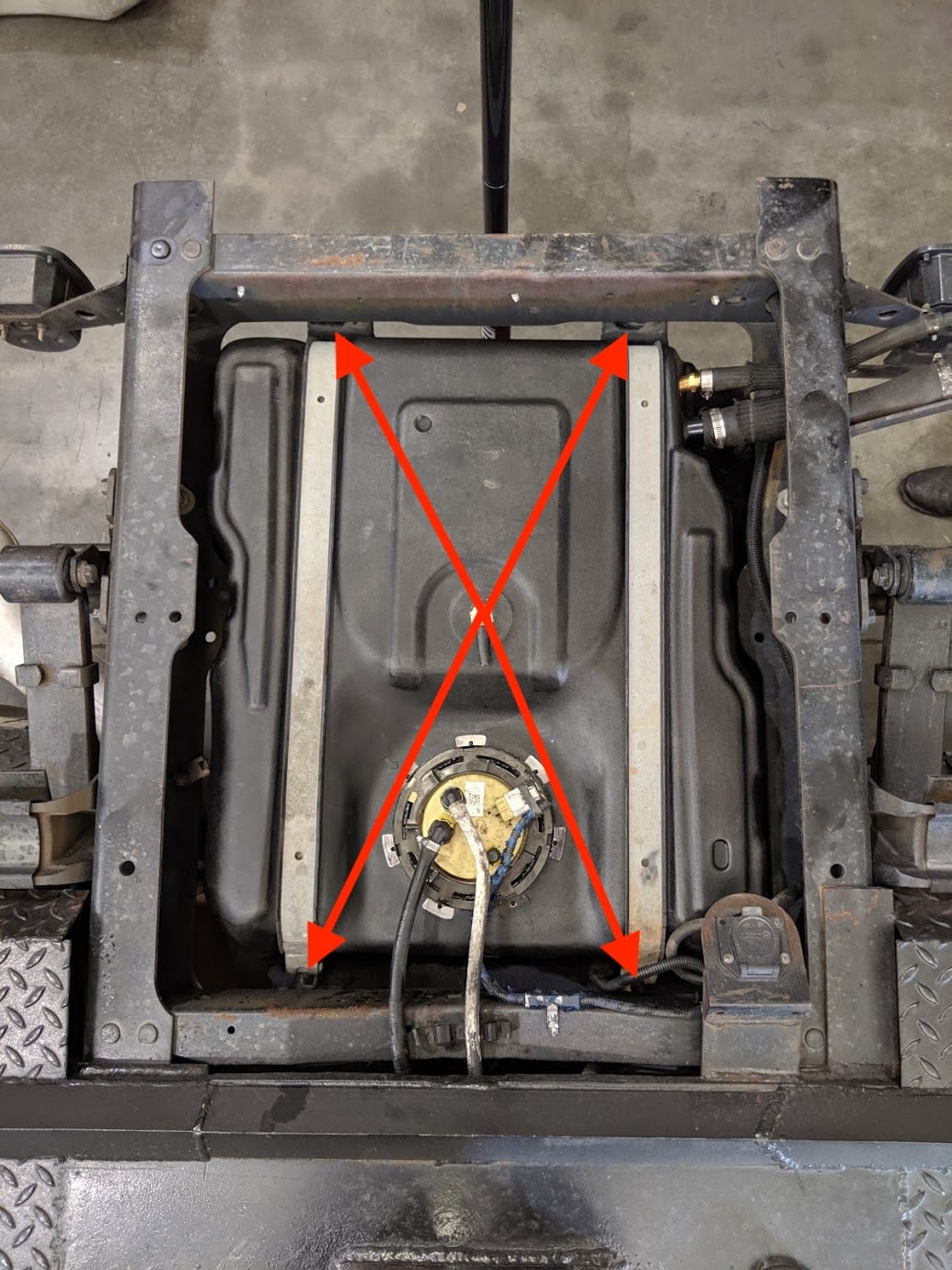
Lower the tank 6" until you can easily reach the fuel sending unit to disconnect all connectors.

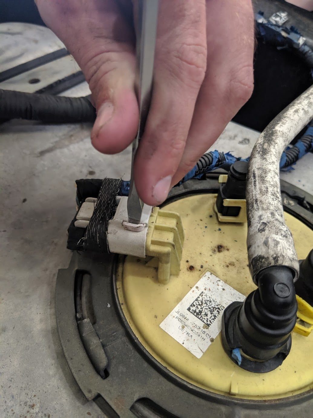
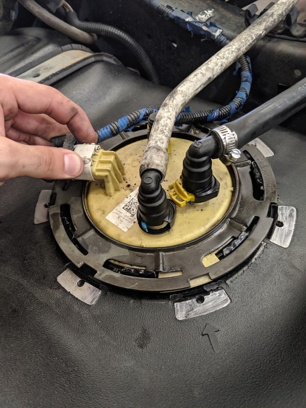
Remove the electrical connector on the sending unit. Use a screwdriver or pick to slide the red locking tab out, then depress the tab and the connector will release.
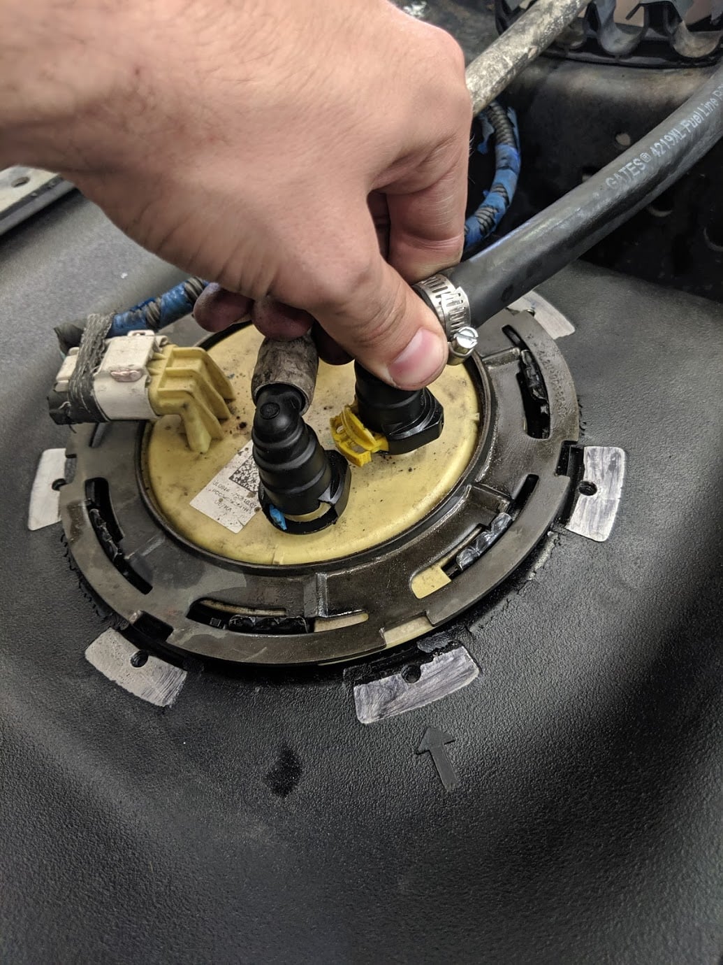
Slide the locking tab at the bottom of the fuel line connectors out. Be gentle as these connectors can become brittle with age.
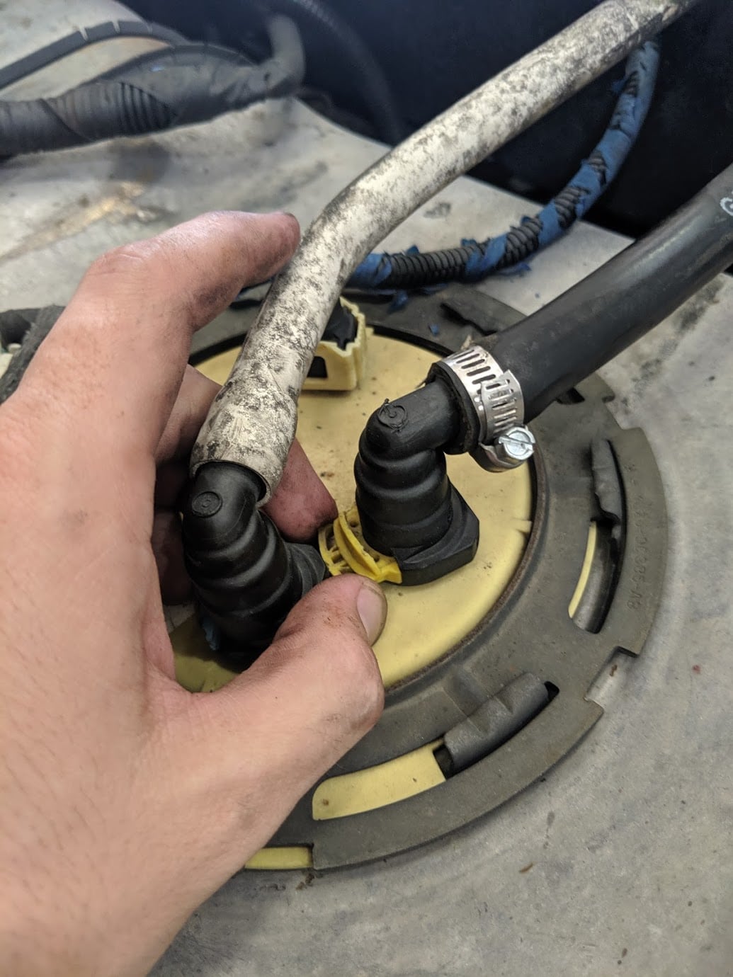
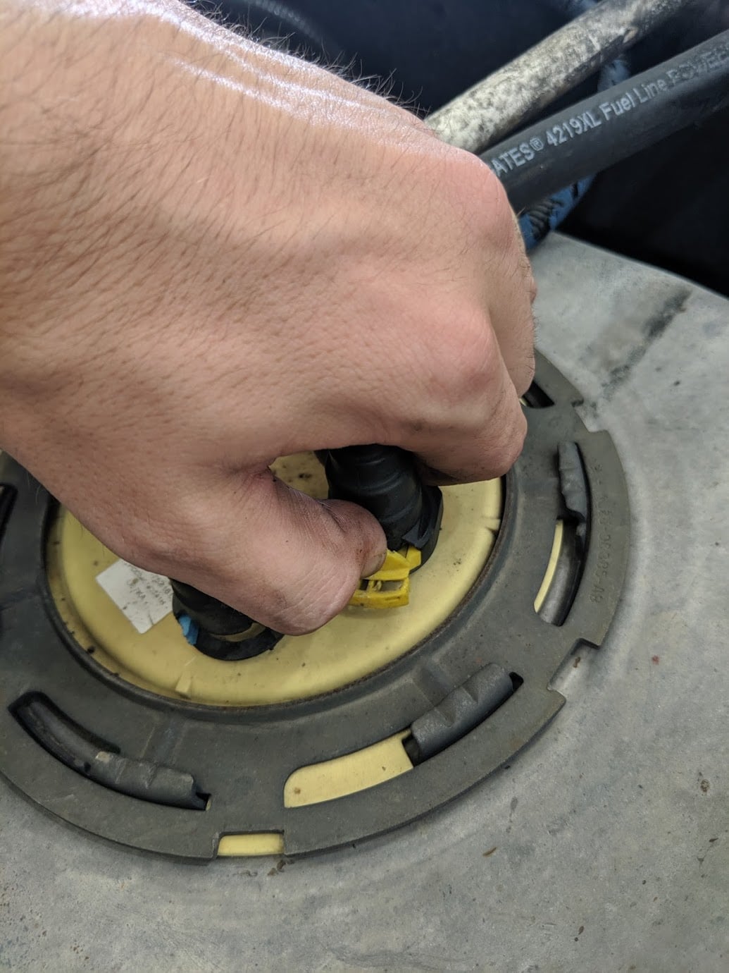
Now that the locking tabs are slide out, depress the upper tab, push down on the connector, then pull up. The connector should release. These connectors can sometimes be the hardest part of the install.
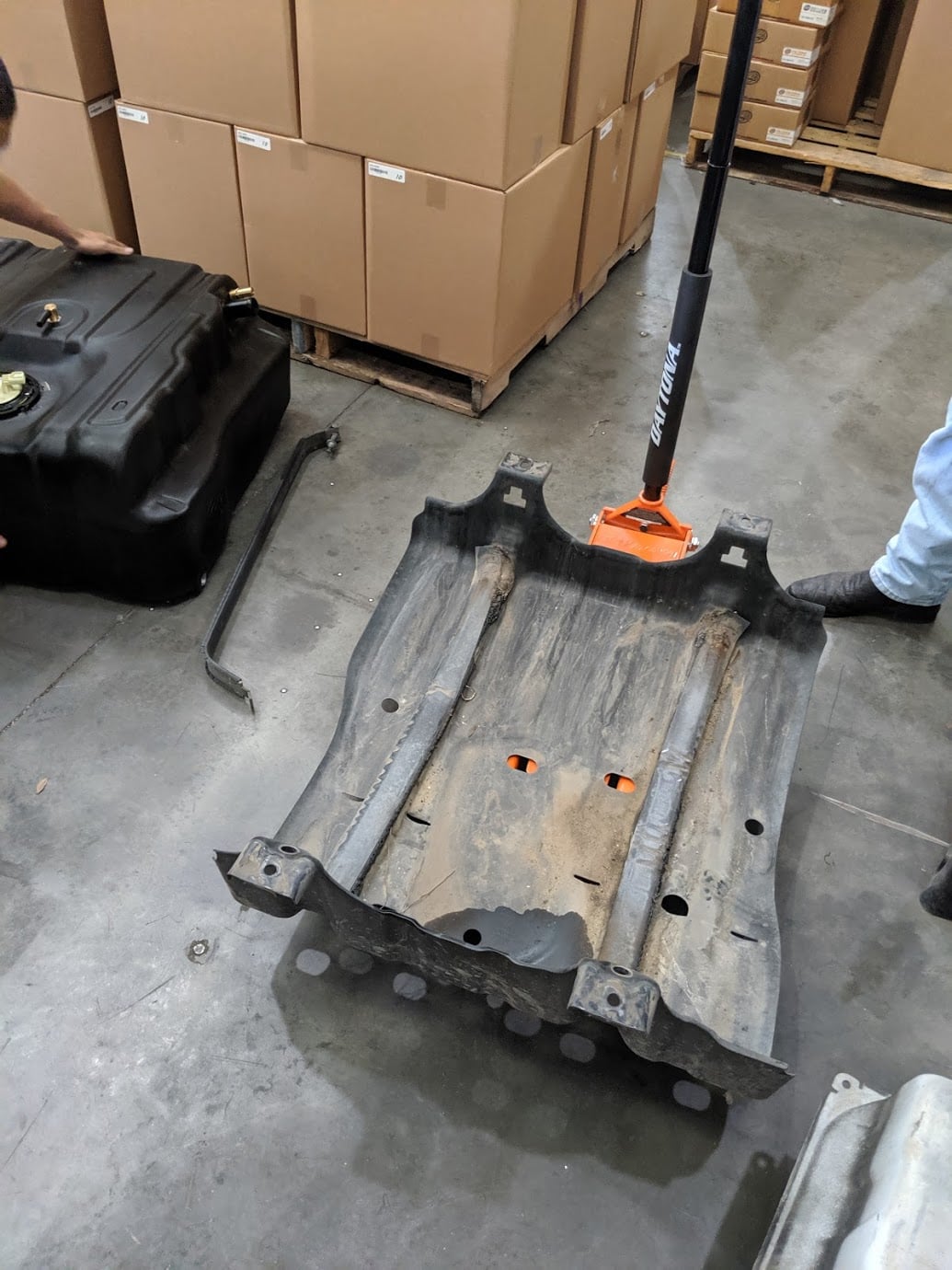
Now the tank is completely disconnected from the vehicle and can be lowered from the vehicle. Ensure the tank is still properly supported as remaining fuel can slosh and cause the tank to move.
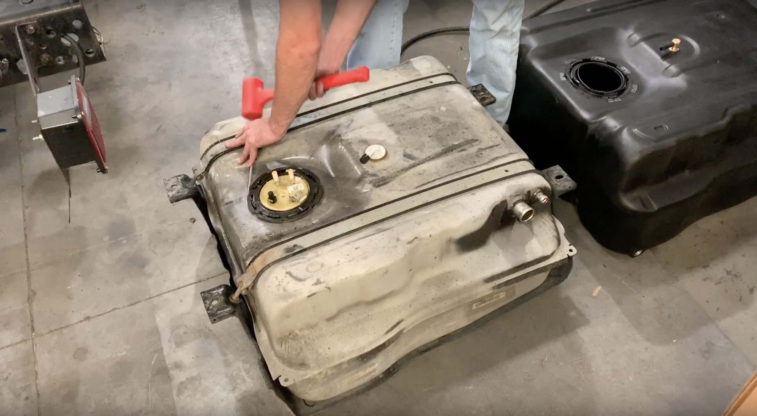
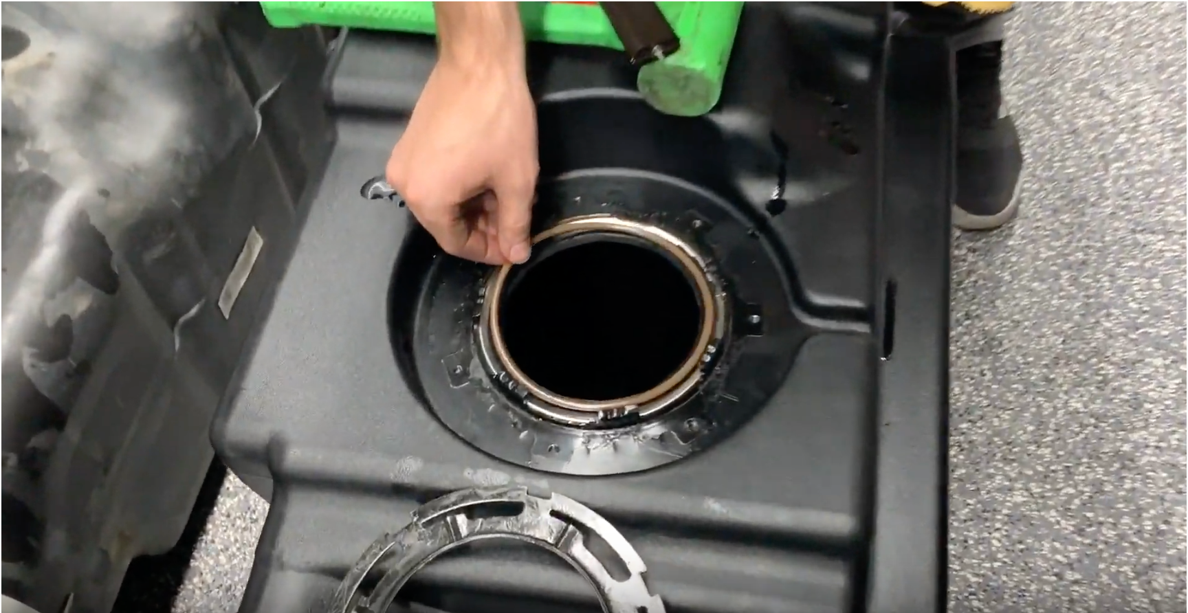
Clean the area around the fuel sending unit to prevent debris from getting into the tank when removing the sending unit. Now use a hammer and flathead screwdriver to remove the OEM sending unit. Position the screwdriver on a locking ring tab and hammer the unit counter clockwise. Once the locking ring is released, remove the sending unit.
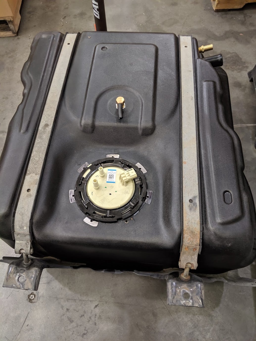
Place the S&B O ring into the groove on your S&B Tank.
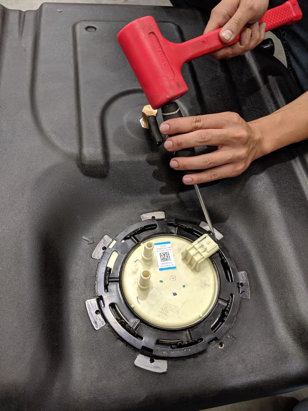
Now place your OEM sending unit in the S&B Tank. Make sure the knob on the sending unit is pointing towards the arrow molded into your S&B Tank. Be careful to not bend the float when installing the sending unit. Place the OEM locking ring on and hammer it clockwise.
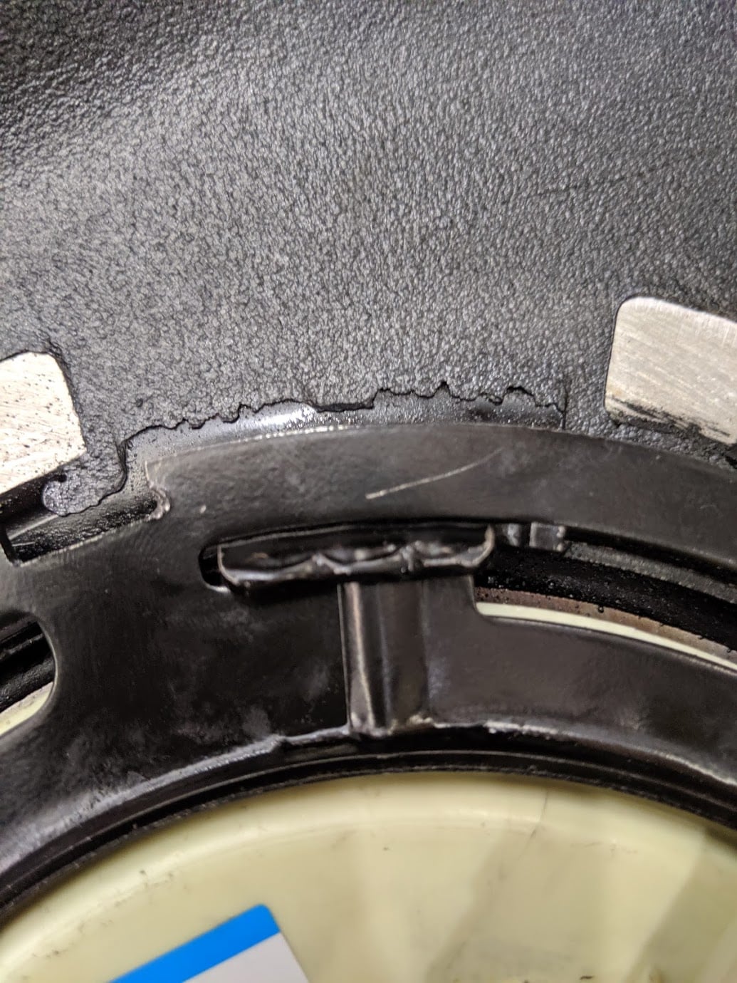
Make sure you rotate the locking ring until the rib on the OEM locking ring is fully seated into the indentation on the S&B receiving ring.
On the OEM fuel tank, use a 19 metric socket to 2 strap bolts which hold the stock fuel tank into the skid plate.
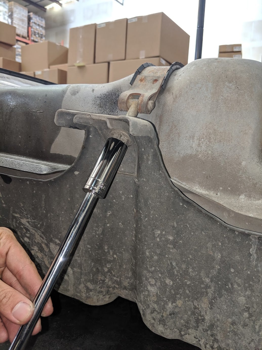
Remove the OEM tank from the skid plate. You may have to pry to get the OEM tank to pop out of the skid plate. Optional Tools
Place the S&B Tank in the OEM skid plate, reassemble the straps using a 19mm socket.
Position the S&B Tank on a jack and raise the tank until you are able to reconnect sending unit connections. Ensure the vent lines are positioned through the frame properly.
Reconnect the electrical connector on the sending unit. Slide the red locking tab back into the locked position.
Reconnect the fuel line connectors by pushing down until they are fully seated. Push the fuel connector locking tabs back in once the connectors are fully seated.
With a 15 metric socket, reinstall the 4 bolts that hold the fuel tank skid plate assembly to the truck frame. Hand torque the bolts to make sure all 4 bolts are tight.
Slide the vent hoses onto your S&B Tank and use a flathead screwdriver to tighten hose clamps.
If you have had any questions, please call or text us at (909)675-1313. If you installed your S&B Tank because of de-lamination issues, we recommend cleaning your fuel system and not re using any of the fuel from your previous tank. Thank you for purchasing an S&B Tank.