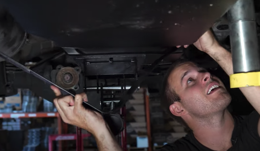
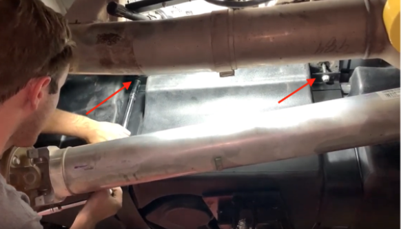
Install Instructions for 10-1021

Before You Start

  • Please read the entire product guide before proceeding
  • Ensure all parts are present.
  • If you are missing any parts, please call or text us at (909)-675-1313
  • Do not work on your vehicle while the underbody components are hot.
  • Make sure the vehicle is in park or the parking brake is set if you plan on working on the ground. If working on a lift, make sure the vehicle is lifted safely and securely.
  • Drain your original fuel tank before beginning the S&B Installation process. S&B Tanks recommends removing only an empty or near empty tank for your safety. We recommend using a siphon or electronic transfer pump.Disconnect and isolate both of the negative battery cables.

    Install time: 3-4 hours.

  • In-bed Auxiliary Fuel Tanks will void the Lifetime Warranty.

  • Nozzle at high flow fuel station may continue to "click off". Tank is designed to work at regular fuel stations.

  • The fuel gauge will continue to work, but the Distance To Empty will still be calculated based on the stock fuel tank capacity. There is no way to change the DTE on the Ram's currently.

  • This tank does contour under the driveshaft in the front. If you have a 4" lift or greater, please check with S&B before ordering as the angle of the driveshaft may cause the tank to touch the driveshaft.

Required Tools

  • Flathead Screwdriver
  • Mallet/Hammer
  • 16mm Deep Socket
  • Ratchet
  • 12" Driver Extension

STEP 1

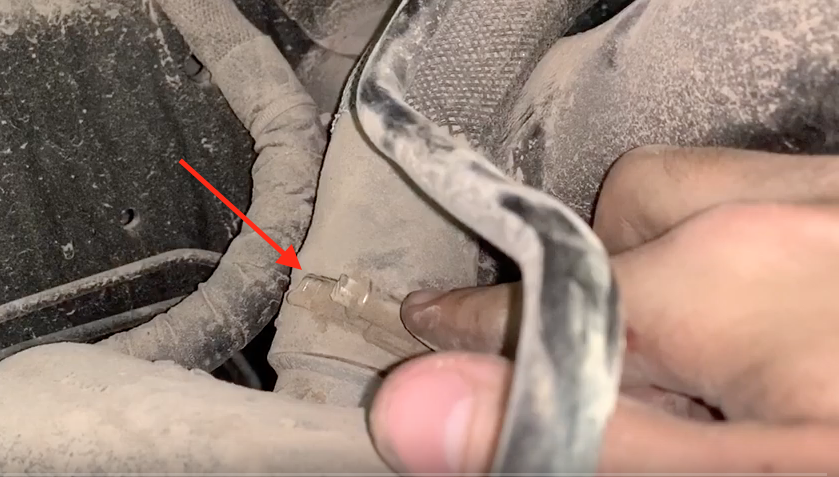
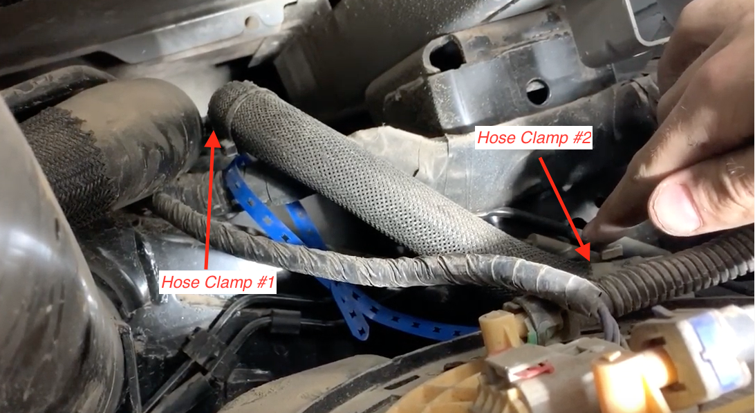
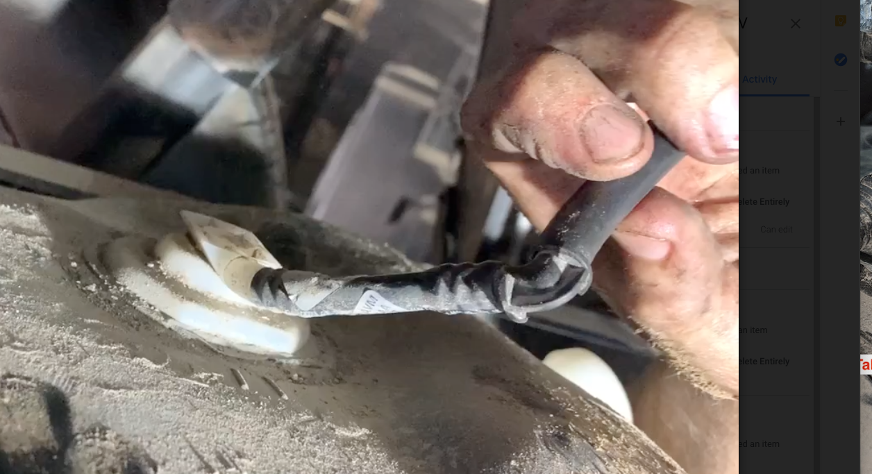
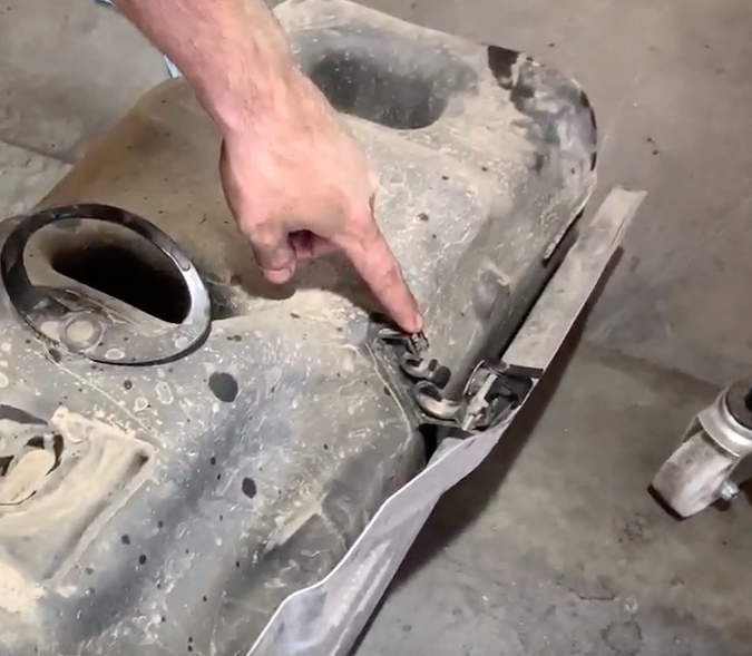
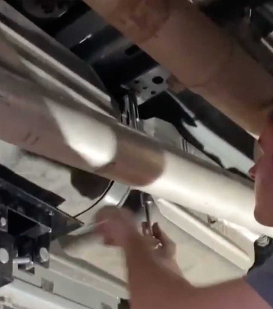
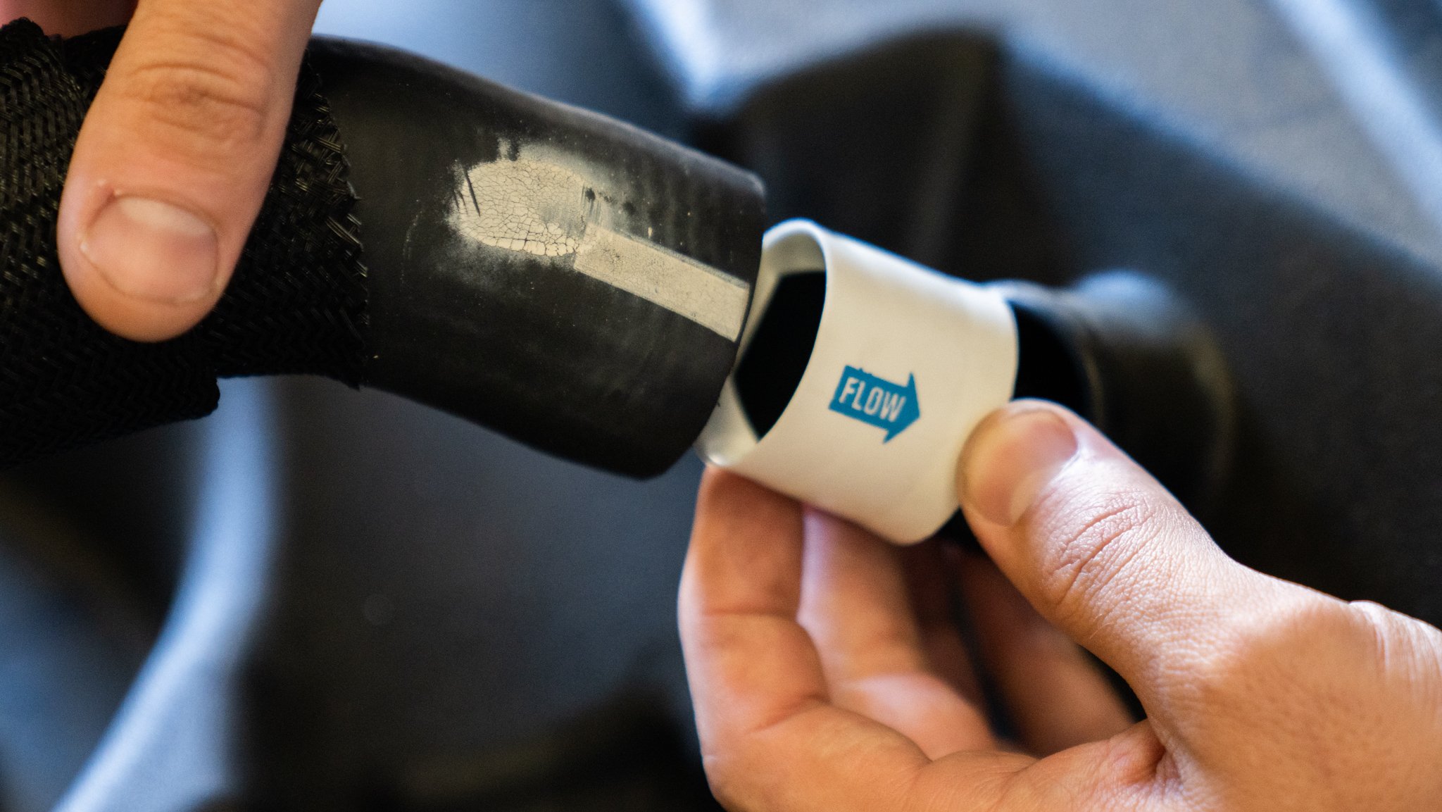
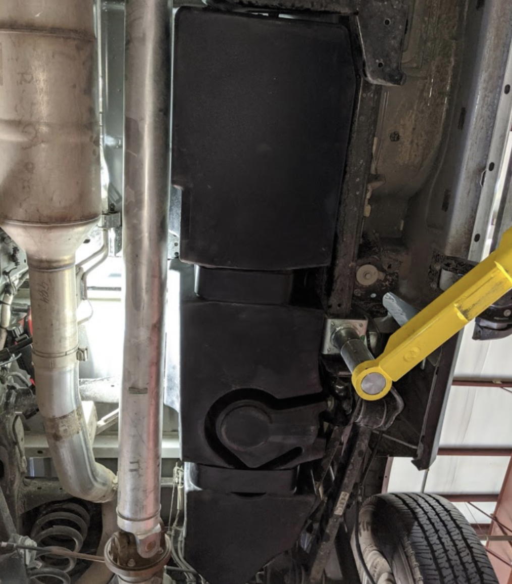
Loosen the hose clamp on the filler hose. The hose clamp on either the tank inlet or the hose clamp connecting the hose to the metal filler neck can be removed. You can find these hose clamps by following the filler neck down from the bed to the tank.


STEP 2

Loosen the hose clamp on the vent hose. The hose clamp that connects the hose to the tank(#2 in the picture) or the hose clamp that connects the vent hose to the metal vent tube(#1 in the picture) can be loosened.


STEP 3

Disconnect the rear rollover vent tube from the barb plastic piece on the tank.


STEP 4

Release the DEF lines from the bracket on the OEM tank(only on 2013 Ram trucks)


STEP 5

- Disconnect the feed line, return line and electrical connector from the sending unit.

- Blue Connector: Pull out the blue slide and depress the button at the base of the connector. Push the connecter gently in, then away from the nipple.

- Green Connector: Depress both green sides and pull off the connector

- Electrical Connector: Slide out the red tab with a pick or flat-head screwdriver then depress the tab on the connector and slide off.


STEP 6

If you are working with the truck on a lift place a jack centered under the tank. Remove the OEM fuel tank straps. These are 16mm nuts that hold the straps to the studs. When removing the straps from the frame side, you will need to push the strap up to release the strap from the cradle.


STEP 7

After the tank has been dropped. Remove the OEM fuel sending unit locking ring from the tank by hitting the ring counterclockwise. The OEM o'ring won't be used again.


STEP 8A

Place the S&B o'ring into the o'ring groove then drop the sending unit into the tank. The tab on the sending unit should face the arrow on the S&B Tank on 2013 trucks. On 2005-12 trucks the tab will need to be trimmed and should be facing in the direction shown in step 8a


STEP 8B

The direction the sending unit should be facing on 2005-12 trucks. Be careful to only trim the tab and not the sealing surface on the sending unit flange. The cut we made is shown below


STEP 8C

A small section will need to be taken off the tab on 2005-12 sending units to fit inside the ring on the tank.


STEP 9

Drop in the OEM sending unit into the S&B Tank. The retaining ring included with the tank will be used


STEP 10

Place the included locking ring over the sending unit flange. First, by pressing down on the ring, get the ring started under the teeth on the tank. Once started, hit the ring clockwise until it passes under the indentation on tank teeth


STEP 11

Ensure the locking ring is fully rotated until the rib on the OEM locking ring(point A) is PAST the indentation on the S&B receiving ring(point B).


STEP 12

Poke a small hole in the rubber cap covering the filler spout on the S&B Tank, block off the openings in the tank with electrical tape or cover with fingers, spray the sending unit o'ring area with soapy water and pressure test the tank to make sure the o'ring was properly seated and there are no leaks in the tank.


STEP 13A

Transfer over the fill hose and put in onto the S&B Tank. Take the vent hose clamp from the OEM tank and reuse this hose clamp with the S&B vent line.


STEP 13B

Before putting the filler hose onto the tank, place the white check valve into the filler hose with the blue arrow facing into the tank opening


STEP 14A

Lift the tank up into position making sure the vent and fill hose goes over the frame. Then install the front and rear straps. The strap bend on the frame side will need to be straightened out to be able to get the strap hooks into the frame. Push the strap hole through the stud on the driveline side and get the nut started. If the fill and vent lines are over the frame and the electrical connectors are free you are fasten the nuts onto the studs. Make sure the straps are tight to prevent tank movement.


STEP 14B

Tighten the OEM nut to the stud and double check to make sure it is secure(45 ft. lbs).


STEP 15A

Reconnect the feed line, return line and electrical connector. Make sure the connectors are locked. To make sure they are locked, gently pull on the connectors to make sure they won't come off and are locked in.


STEP 15B

If the electrical connector is not long enough, install the included S&B electrical connector.


STEP 16

Reinstall the rollover vent line onto the rear 5/16" barb


STEP 17

Reinstall the hose clamps on the fill and vent lines. Once these are connected, you are ready to put fuel in the tank. Please read the final checklist below to make sure everything was accounted for


Step 18 FINAL CHECKLIST

This final checklist is very important.

#1 Make sure all nuts are safely fastened and torqued.


#2 Ensure there is proper driveshaft clearance and the straps are tight


#3 Double check fuel line connections, the electrical connection as well as the vent and fill lines.


#4 Lastly, fill the tank full and check for any leaks.


If you have any questions, call or text us at 909.675.1313