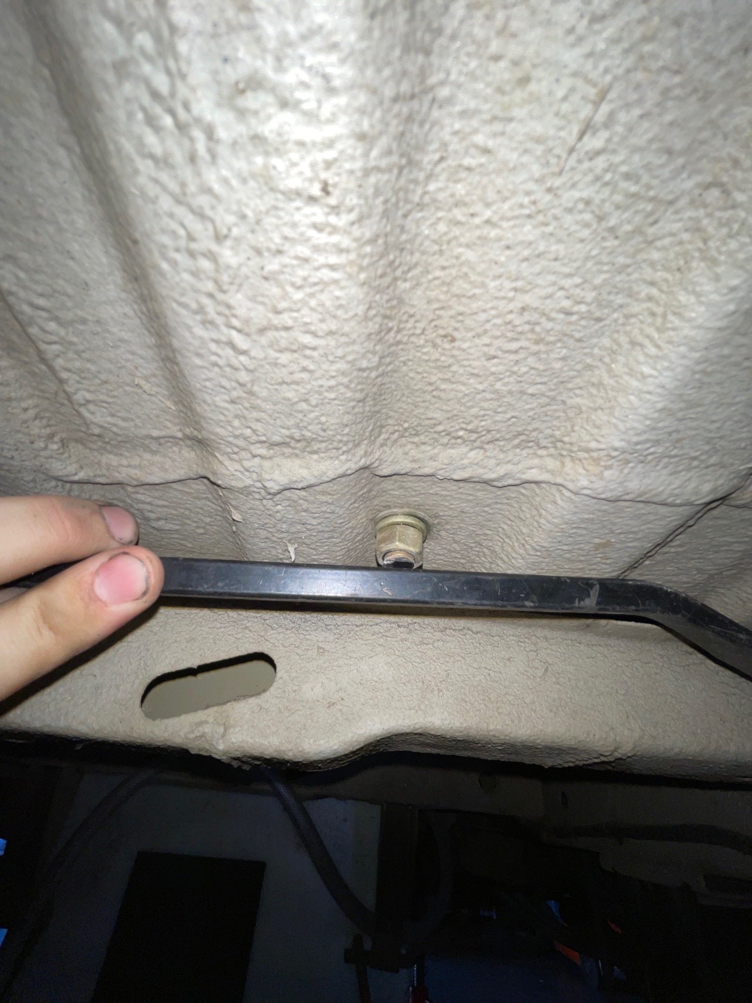
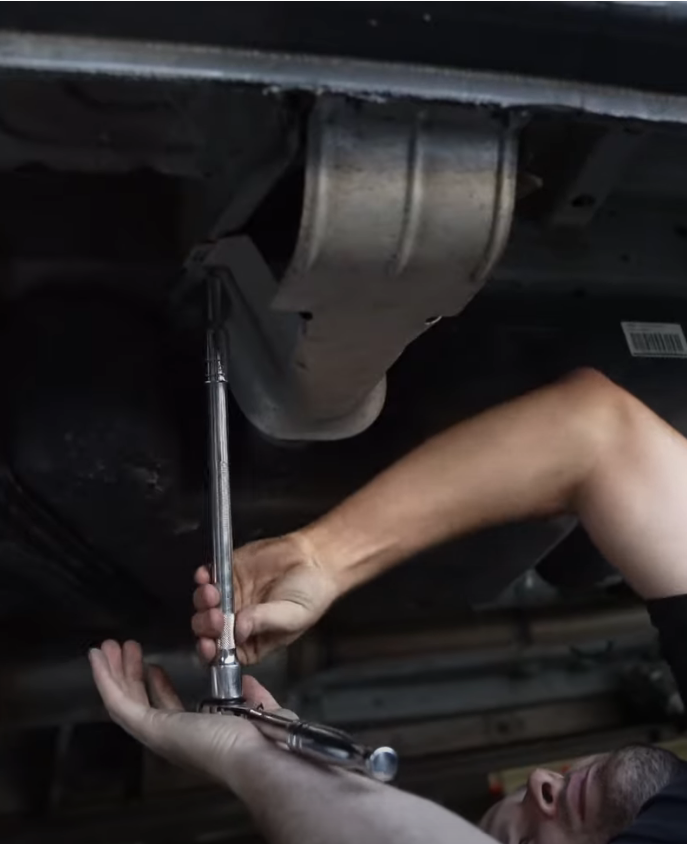
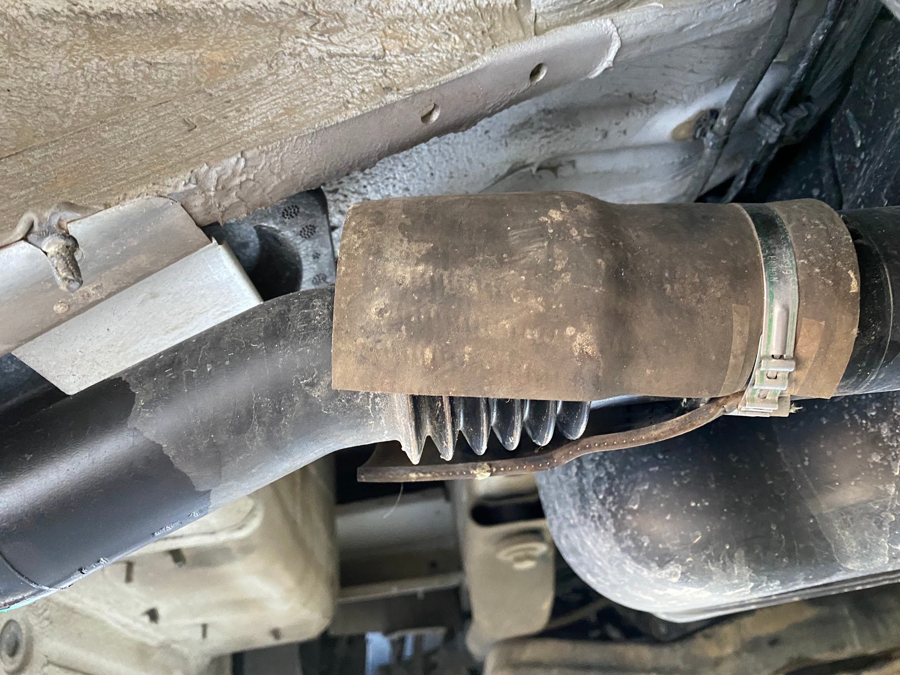
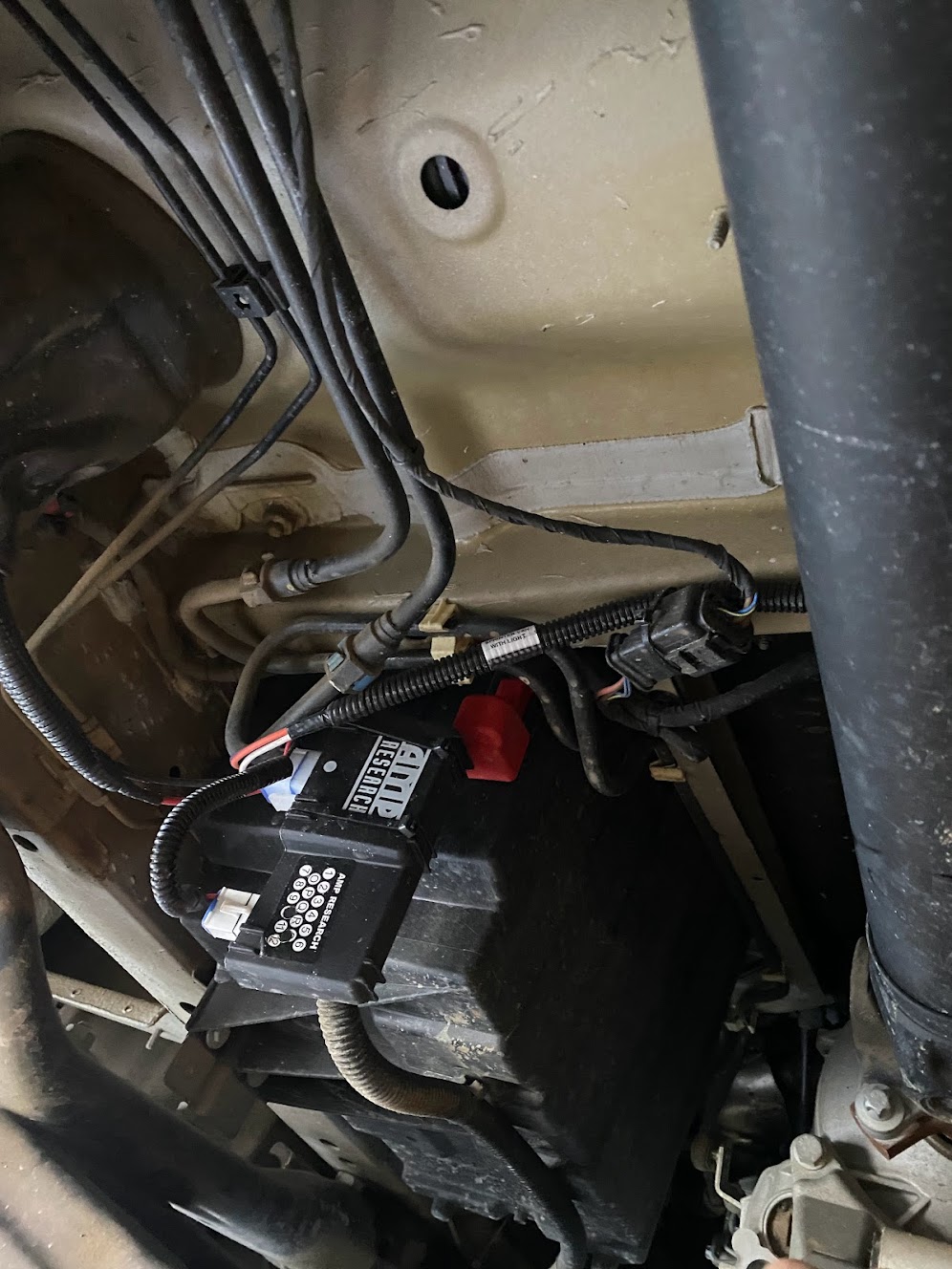
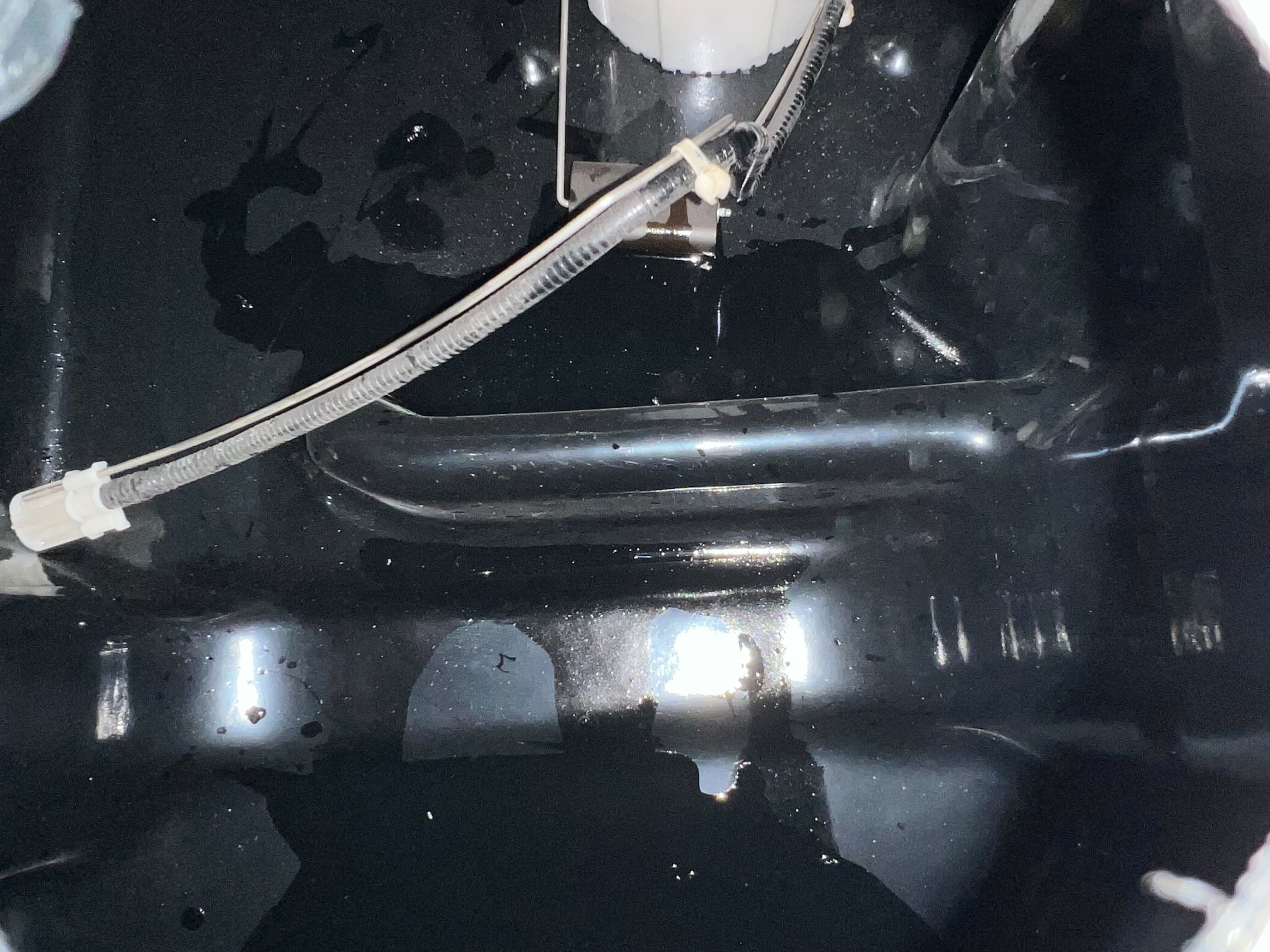
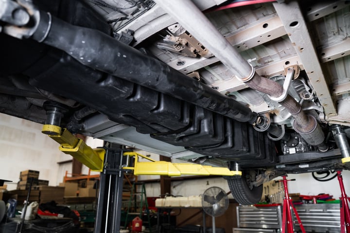
Install Instructions for 10-1026

Before You Start

  • Please read the entire product guide before proceeding
  • Ensure all parts are present.
  • If you are missing any parts, please call or text us at (909)-675-1313
  • Do not work on your vehicle while the underbody components are hot.
  • Make sure the vehicle is in park or the parking brake is set if you plan on working on the ground. If working on a lift, make sure the vehicle is lifted safely and securely.
  • Disconnect and isolate both of the negative battery cables
  • Before installing S&B Tank, conduct pressure test to ensure o'ring is properly seated.
  • Auxiliary Fuel Tanks will void the Lifetime Warranty.
  • DIESEL FUEL ONLY

Required Tools

  • Flathead Screwdriver or 5/16" Nut Driver
  • Mallet/Hammer
  • 11mm Socket
  • 3/4" Socket
  • 3/4" Drill Bit
  • 2" Pipe cutter or hand saw
  • Ratchet
  • 12" Driver Extension

STEP 1

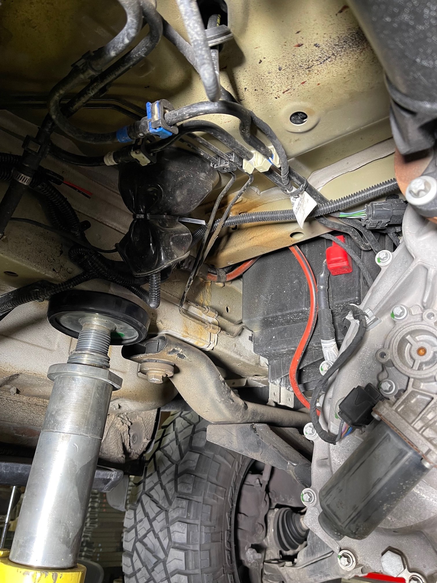
Inspect the underside of the Vehicle for any obstructions, bolts, or screws from any accessories that may be installed inside that may protrude through the floor around or near the gas tank. All bolts above S&B Tank must not extend longer than the female portion of the floor.


STEP 2

Start by removing the fuel filler cover with a 10mm socket.


STEP 3

Remove the 4 bolts holding the plastic cover to the van with a torx t30


STEP 4

Remove the screw holding the filler pipe to the van.


STEP 5

Remove the silver plate cover and foam black insert behind the silver cover. Reach inside the hole for the filler next and disconnect the electrical ground


STEP 6

Disconnect the feed and return fuel lines as well as the electrical connector. If you have the auxiliary fuel tap connected, disconnect this connector as well. The auxiliary fuel tap comes from the same location as the other 2 fuel lines but it is much smaller.


STEP 6B

This is the unlocked position for the fuel connectors. Pinch the same tabs together and push them into the connector.


STEP 7

With something supporting the bottom of the tank, remove all 6 fuel tank strap bolts using a 10mm socket. The bolts will be reused.


STEP 8

Remove the original sending unit from the original tank. You may need to use a lock ring tool which can be found at oreilly (Part # W80668)


STEP 8B

Place the included black S&B oring into the oring groove on the S&B Tank. Then put the original sending unit into the S&B Tank. Make sure the black venturi "snake" does not interfere with the float


STEP 8C

Remove the 5 bolts holding down the main vent and remove the vent so you can see inside.


STEP 8D

Use a flash light or take a picture in the tank to make sure there is separation between the float and venturi tube.


STEP 8E

This is what it looks like if the sending unit is NOT installed incorrectly and the tube is hitting the float. This would lead to the gauge getting stuck and the gauge eventually falling and not moving from empty.


STEP 9

Disconnect the electrical, feed and return lines, as well as the fuel aux tap if there is not a cap on the end. Then poke a hole in the filler cap. Spray the sending unit area with soapy water. Block off the tank openings and pressurize the tank through the hole in the filler.


STEP 10

Get the locking ring threads started by hand then tighten with the pictured tool or punch and mallet.


STEP 11

Cut the vent hose off the original tank at the point where the vent nipple ends inside the hose.


STEP 11B

Zip tie the rear 5/16" vent hose to the main line (pictured)


STEP 12

If your original fuel tank has an accordion on the filler pipe. Make the cut here. You can either use a pipe cutter or hand saw to make the cut. If you use a hand saw, make sure plastic pieces don't get into the tank.


STEP 12B

If your tank does not have the accordion on the filler, make the cut here.


STEP 12C

Insert the check valve into the included rubber hose and install it onto the tank.


STEP 12D

Connect the original filler neck to the S&B Tank with the included 2 hose clamps


STEP 13

Lift the tank into place and reconnect fuel lines and electrical connector from step 6


STEP 14

Tighten all 6 bolts.


STEP 15

Tighten the hose clamps(1 each side of the rubber hose). Then reinstall the filler neck covers and electrical ground.


STEP 16

Reinstall the screw that holds the filler to the van and the 4 bolts that hold the cover over the filler.


Step 17 CHECKLIST

This final checklist is very important. #1 Make sure all nuts are safely fastened and torqued. #2 Ensure there is proper driveshaft clearance and the straps are tight #3 Double check fuel line connections, the electrical connection as well as the vent and fill lines. #4 Lastly, fill the tank full and check for any leaks. If you have any questions, call or text us at 909.675.1313