Install Instructions for 75-5061-1

Before You Start

  • Please read the entire product guide before proceeding.
  • Ensure all parts are present.
  • If you are missing any of the components, call our customer support at (909) 947-0015.
  • Do not work on your vehicle while the engine is hot.
  • Make sure the engine is turned off and the vehicle is in Park or the Parking Brake is set.
  • Note: This intake kit may not fit with the following Aftermarket Parts installed: Body Lift or Lowering Kit, Custom Hood Throttle Body Spacer / Upgrade

Required Tools

  • 10 mm socket or wrench
  • 3/16" hex socket or key*
  • 5/16" drill bit and drill*
  • 5/16" nut driver or flat blade screwdriver
  • 1/4" nut driver or flat blade screwdriver
  • Phillips screwdriver
  • 9/16" wrench
  • plastic trim tool or flat blade screwdriver
  • *If equipped with pressure sensor

STEP 1

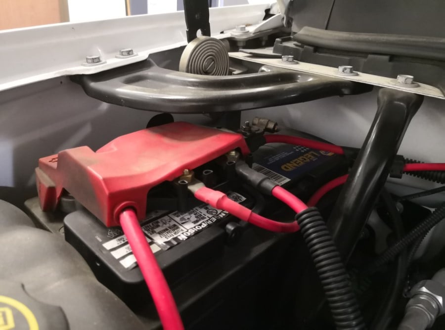
With the ignition switched off and the parking brake set, disconnect the negative battery cable from the battery or batteries if you have more than one.

IMPORTANT: Failure to disconnect the battery for a minimum of 2 hours may cause the Check Engine Light to illuminate upon completion of the installation or subsequent operation. DO NOT SKIP THIS STEP!

STEP 2

Remove the engine cover by lifting it up out of the grommets, then pull towards the front of the vehicle.


STEP 3

Disconnect the crankcase vent tube from the intake resonator by gently pulling it out.


STEP 4

Disconnect the other end of the vent tube from the engine by sliding the locking tab over and pulling the tube to remove it.


STEP 5

Disconnect the MAF sensor harness connector and the pressure sensor harness connector (if equipped).

STEP 6

Loosen the hose clamp connecting the intake tube to the throttle body.


STEP 7

Loosen the hose clamp connecting the intake tube to the air cleaner assembly.


STEP 8

Using a suitable tool, gently pry the intake tube off the retainer clip on the coolant hose. Remove the intake tube.


STEP 9

Remove the airbox by pulling it up out of the grommets, then remove the four screws securing the metal tray. Remove the metal tray.


STEP 10

For the coldest intake air possible, install the silicone box plug by pushing it in from inside the airbox. It can be removed if maximum airflow is desired more than the coldest intake air temperature.


STEP 11

Install the silicone tube seal into the airbox by pushing it into the circular opening.


STEP 12

Install the airbox into the vehicle using the four M6 x 25 mm screws and washers.


STEP 13

Remove the MAF sensor from the OE airbox using the T15 Torx key provided. Remove the pressure sensor (if equipped).


STEP 14

ONLY IF equipped with a pressure sensor, drill out the hole in the intake tube for the pressure sensor using a 5/16" drill bit. Make sure the drill bit is centered, do not damage the sides of the hole where the pressure sensor o-ring makes contact. Thoroughly clean the inside of the tube of all debris. Install the pressure sensor using the 1/4"-20 x 7/8" socket head screw provided.


STEP 15

Install the plastic MAF mounting adapter on to the MAF sensor. Then, install the foam gasket. The shape of the foam gasket should match the adapter, if not, try flipping it around.


STEP 16

Install the MAF sensor with an adapter and gasket on to the intake tube using the #8-32 x 7/8" screws. Note: the foam gasket should be between the intake tube and the plastic adapter.


STEP 17

Install the 90° hose barb into the tube finger tight. Then, using a wrench, tighten it one complete revolution, then tighten it further to the orientation shown.


STEP 18

Install the larger side of the silicone coupler on to the intake tube and install a size #72 hose clamp as shown. Leave it loose for now.


STEP 19

Install a size #64 hose clamp on the smaller side of the silicone coupler. Install the tube by pushing the filter end through the tube seal in the airbox, then pushing the silicone coupler on to the throttle body. Make any adjustments to the fit as necessary and tighten the hose clamps.


STEP 20

Install the filter by pushing it through the large opening in the airbox. You may have to squeeze the sides a little to get it through. Push the filter on to the end of the intake tube, you may have to rotate the filter to make sure it has clearance all around it. Tighten the size #88 hose clamp to secure the filter.


STEP 21

Slide the two size #6 hose clamps over the 12" long crankcase breather hose. Connect the hose to the 90° hose barb. Connect the other end to the crankcase fitting on the engine. Tighten the hose clamps. Reconnect the MAF sensor (and pressure sensor if equipped) electrical connector(s).


🛑 Stop! Read This Before Continuing The Install

If your kit came with our new snap-in lid design, please proceed to STEP 23 to install your snap-in lid. If your lid is the traditional screw in lid, please proceed to the next step.


STEP 22

Remove the protective paper from the clear lid. Don't forget the small pieces inside the logo. Install the lid edge trim if desired, trim the ends to length if necessary. Install the four #10-24 screws with the plastic countersunk washers finger tight to secure the lid. Do not over-tighten.

Go To Step 25


STEP 23

For Snap-In Lids Only

Remove the protective covering from the Clear Lid.


STEP 24

For Snap-In Lids Only


Stretch silicone lid seal around the perimeter of the clear lid. It should be a snug fit.

STEP 24 (Image 2)

For Snap-In Lids Only

The notch on the lid and the tab of the lid seal should mate in the same corner.


STEP 25

Reinstall the engine cover and reconnect the battery. Inspect the installation to make sure everything is secure, all fasteners and hose clamps have been tightened, sensors reconnected, etc. The installation is now complete.