STEP 1
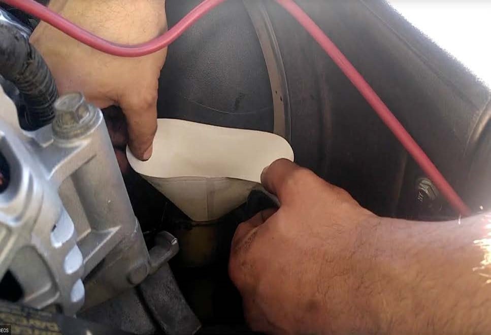
With the ignition switched off and the parking brake set, disconnect the negative battery cables on both batteries, then disconnect the positive battery cable on the driver’s side only. Use a 8mm socket.
IMPORTANT: Failure to disconnect the battery for a minimum of 2 hours may cause the Check Engine Light to illuminate upon completion of the installation or subsequent operation. DO NOT SKIP THIS STEP!


.jpg?v=1722875035501)