Install Instructions for 75-5070

Before You Start

  • Please read the entire product guide before proceeding.
  • Ensure all parts are present.
  • If you are missing any of the components, call our customer support at (909) 947-0015.
  • Do not work on your vehicle while the engine is hot.
  • Make sure the engine is turned off and the vehicle is in Park or the Parking Brake is set.
  • Note: This intake kit may not fit with the following Aftermarket Parts installed: Aftermarket Parts installed, Body Lift or Lowering Kit, Custom Hood, Intercooler or Turbo upgrades

Required Tools

  • 8mm & 10mm Wrench & Socket
  • Phillips Screwdriver
  • 5/16” Nut Driver or Flat Blade Screwdriver

STEP 1

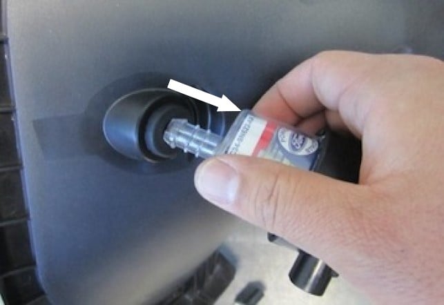
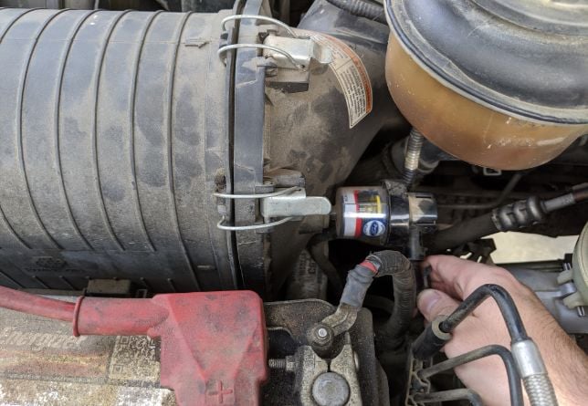
With the ignition switched off and the parking brake set, disconnect the negative battery cables.

IMPORTANT: Failure to disconnect the battery for a minimum of 2 hours may cause the Check Engine Light to illuminate upon completion of the installation or subsequent operation. DO NOT SKIP THIS STEP!

STEP 2

If Equipped: Disconnect the electrical connection at the OE restriction gauge located at the back of the airbox.

STEP 3

Depending on your vehicle year, disconnect either the MAF sensor or the Temp. sensor electrical connection on the OE intake tube.


STEP 4 (Two Piece Intake Tube)

If you have the OE “Two Piece” intake tube, loosen the hose clamp at the bellows.


STEP 4 (Two Piece Intake Tube) Image 2

STEP 4 (One Piece Intake Tube)

If you have the OE “One Piece” intake tube, loosen the hose clamp at the turbo flange. Then Pull the OE breather tube from the valve cover.


STEP 4 (One Piece Intake Tube) Image 2

STEP 5

Pull up and out on the OE airbox and tube assembly to remove it from the vehicle. The OE grommets should remain in the tray.


STEP 6

Remove the OE restriction gauge from the OE intake. Place it aside to be used later on during the install.


STEP 7

Prior to installing the Air Box (A), you may need to rotate the OE intercooler clamp that is located just below to add clearance for the Air Box (A).


STEP 8

Install the Box Seal (B) into the Air Box (A). Make sure the Seal is installed completely and sits flush inside the hole in the Air Box. Some force may be needed to properly seat the Box Seal groove into the Air Box hole.


STEP 9

Place the Air Box (A) in the vehicle. Tilt towards the front, then push down on the Air Box to seat the prongs into the OE grommets.


STEP 9 Image 2

If you do not seat the Air Box properly in the OE grommets, there will be interference between the Air Box and the hood when the hood is closed. Check for clearances before you proceed.


NOTE:

If you have the OE “Two Piece” intake tube pictured in step #4(A) you will skip steps #10 thru #14, resume at the note prior to step #15.


STEP 10

Install the Straight Coupler (R) to the turbo flange and secure using the #64 Hose Clamp (F).


STEP 11

Spread the OE clamp open and remove the breather tube assembly from the OE intake tube.


STEP 12

Install the large Grommet (T) into the Short Tube (P) followed by the 90 degrees OE breather tube fitting.


STEP 13

Insert the Short Tube (P) assembly into the Straight Coupler (R). Align the breather tube then secure using the #64 Hose Clamp (F).


STEP 14

Insert the OE breather tube assembly into the valve cover.


TEMP. SENSOR NOTE:

If your vehicle uses a Temp. Sensor in place of a MAF Sensor: Use the supplied Temp. Sensor grommet (M) and install it in the hole of the intake tube (C). Once the grommet is installed insert the Temp Sensor into the grommet.


TEMP. SENSOR (IMAGE 2)

STEP 15

If your vehicle uses a MAF sensor, use the supplied T-20 Torx tool and remove the MAF sensor from the OE intake.


STEP 16

If your vehicle uses a MAF sensor, use the supplied MAF Gasket (K) and #8-32 Screws (L) to attach the MAF sensor to the Intake Tube (C). Do not overtighten.


STEP 17

Place the Block Off Grommet (W) into the Intake Tube (C). Fully insert the groove of the Block Off Grommet in the hole of the Tube and make sure the grommet flange is seated completely around the outside and inside of the tube hole. You can gently use a large flat blade screwdriver to help get the groove of the Grommet to properly seat in the hole. Be careful not to damage the Grommet during installation. After the Grommet is installed, make sure the OE restriction gauge is inserted completely into the Grommet.


STEP 17 (IMAGE 2)

STEP 18

Place the Intake Tube (C) in the vehicle as shown, then rotate the Tube so the MAF sensor or Temp. sensor is facing up.


STEP 20

Insert the Intake Tube (C) into the Box Seal (B).


STEP 21

Make sure the Tube (C) is pushed all the way in until the second bead of the Tube is visible. Position the second bead of the Tube on the inner edge of the Box Seal (B) as shown.


STEP 22

Slide the Coupler (N) over the short intake tube and center it over the gap between the two tubes.


STEP 23

Secure both #72 Hose Clamps (V) after both Tubes and Coupler are aligned together straight.


STEP 24

Carefully place the Air Filter (D) into the Air Box (A). Fully insert the Filter (D) on to the Intake Tube (C) and make sure the Filter is rotated and aligned so that it is evenly spaced within the Air Box. Tighten the #80 Hose Clamp (E) to secure the Filter in place.


STEP 25

Reconnect the restriction gauge to the harness.

NOTE: DO NOT rely on the OE restriction gauge or wait until the dash light is triggered before you service your S&B air filter. The restriction gauge is no longer monitoring the restriction of the filter.

STEP 26

Reconnect the electrical connector to either the MAF Sensor or Temp. Sensor located on top of Tube (C).

STEP 27

Remove the protective film from the Clear Lid (G) including the film around the S&B Logo and place the Lid on to Air Box (A). Secure using the #10-24 Screws (J) and #10 Countersunk Washers (H). Start with one corner then proceed in a star pattern to tighten the Screws.


STEP 28

For increased air flow, we recommend using the provided Inlet Cap (U). However, if you wish to cover the Air Box from possible engine bay heat, use the Clear Lid (G).

STEP 29

Reconnect the battery cables. Inspect your installation. Make sure the kit is properly positioned and all fasteners and hose clamps are secured. Keep all stock parts in case you ever need to reinstall the stock intake. Affix the ID label near the intake kit. If you are an installer, give the owner the QR code for the Installation Instructions so that he/she is aware of the Maintenance, Operation, and Periodic Checking procedures given at the beginning of the instructions. The installation is now complete.