Install Instructions for 75-5085

Before You Start

  • Please read the entire product guide before proceeding.
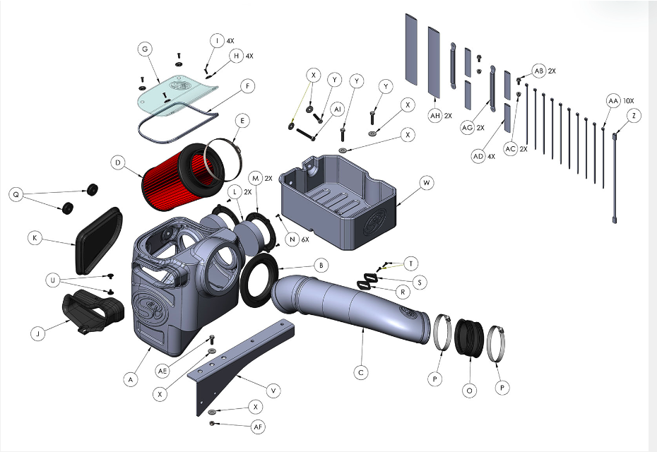
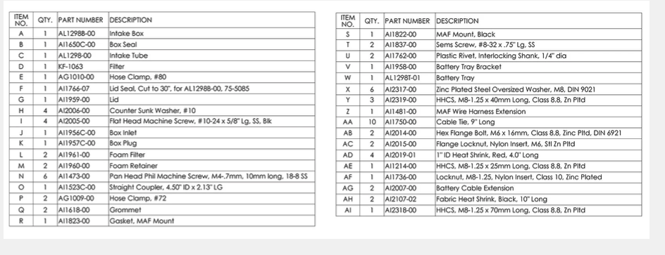
  • Ensure all parts are present.
  • If you are missing any of the components, call our customer support at (909) 947-0015.
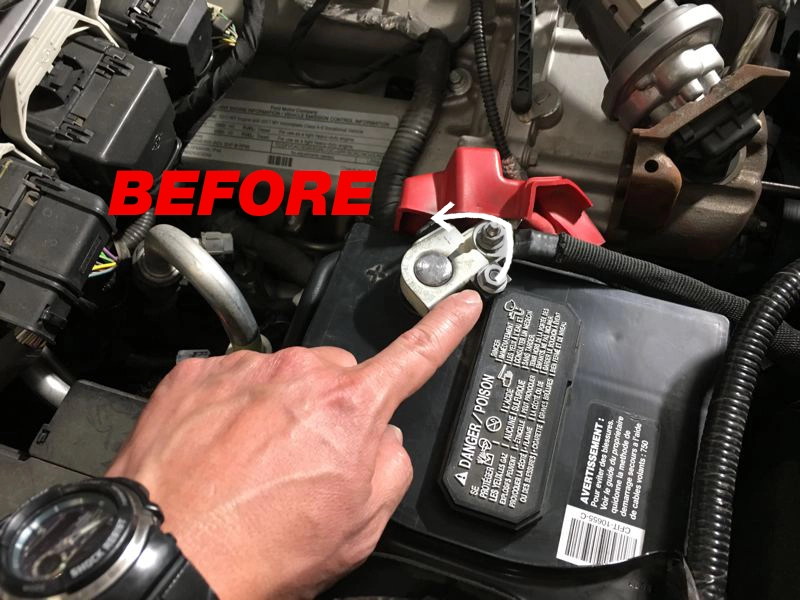
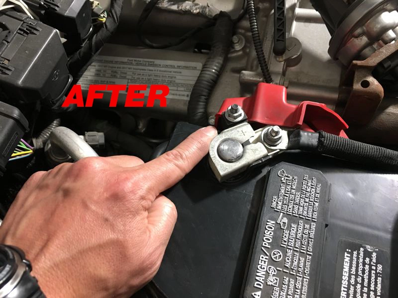
  • Do not work on your vehicle while the engine is hot.
  • Make sure the engine is turned off and the vehicle is in Park or the Parking Brake is set.
  • Note: This intake kit may not fit with the following Aftermarket Parts installed: Body Lift or Lowering Kit, Custom Hood, Throttle Body Spacer / Upgrade


PERIODICALLY CHECK THE FOLLOWING:

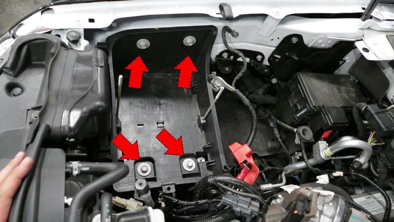
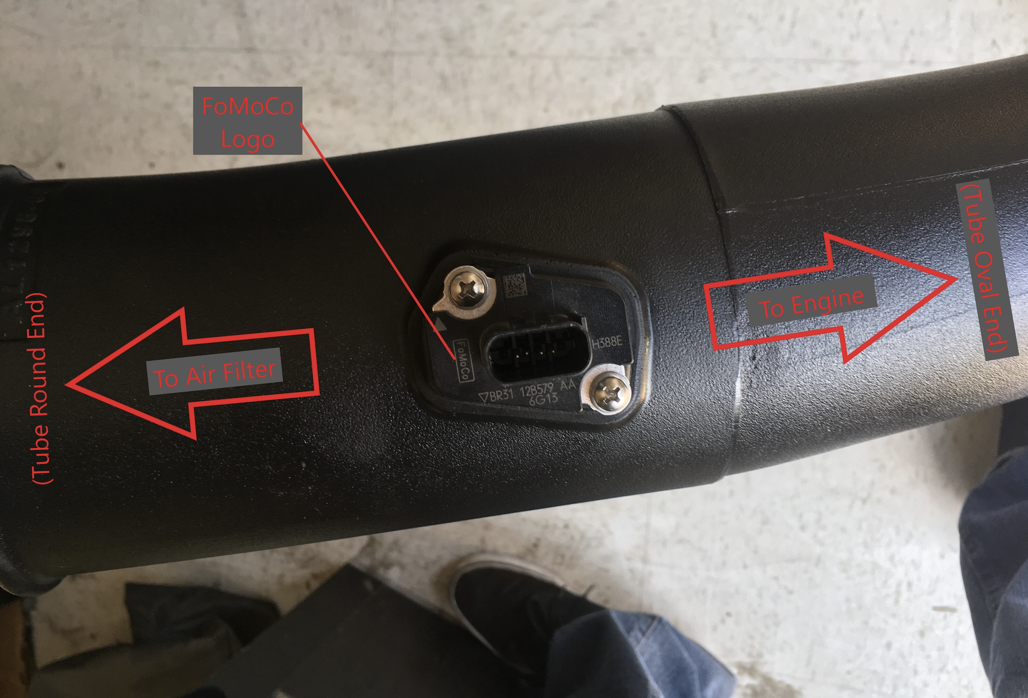
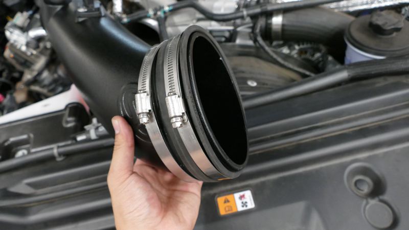
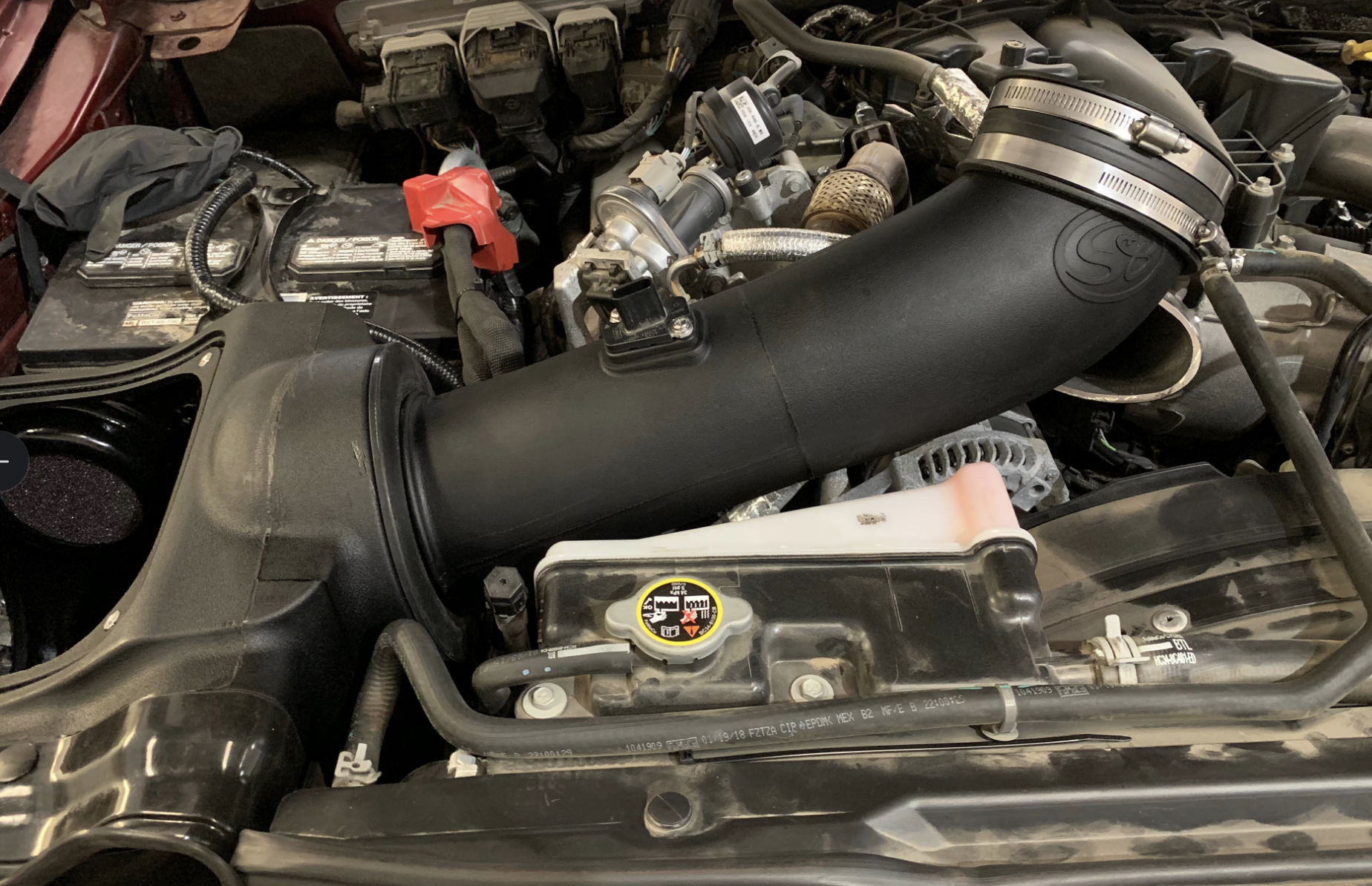
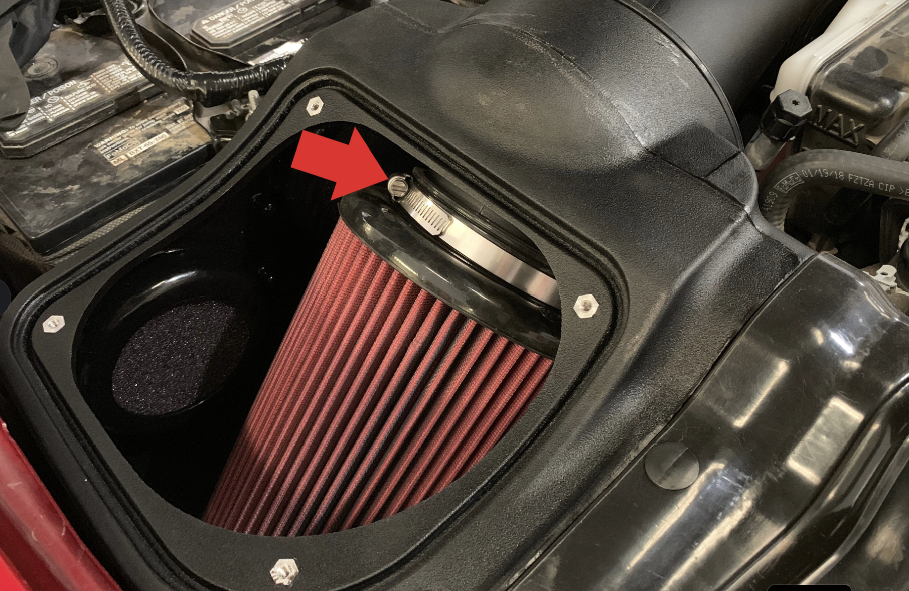
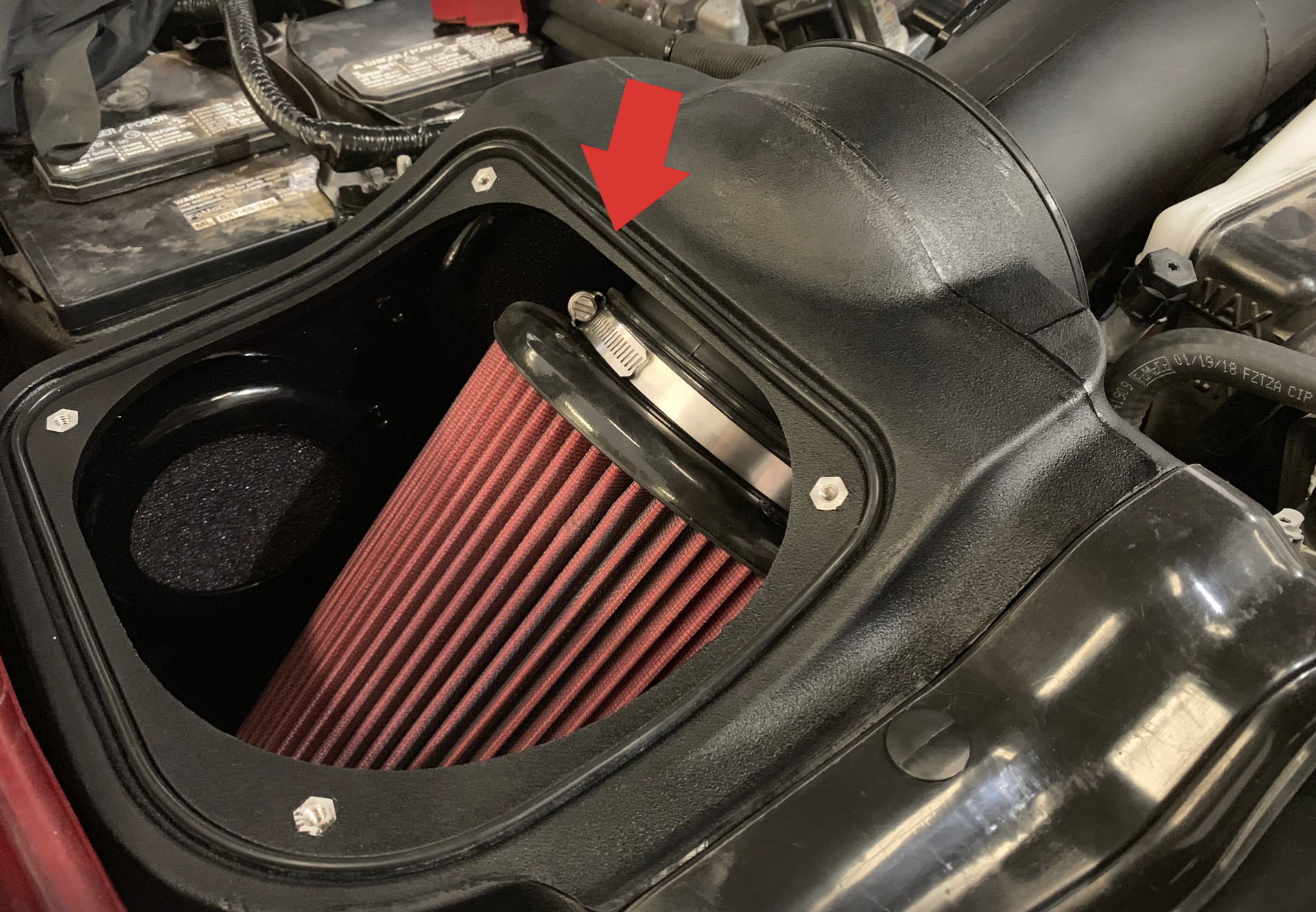
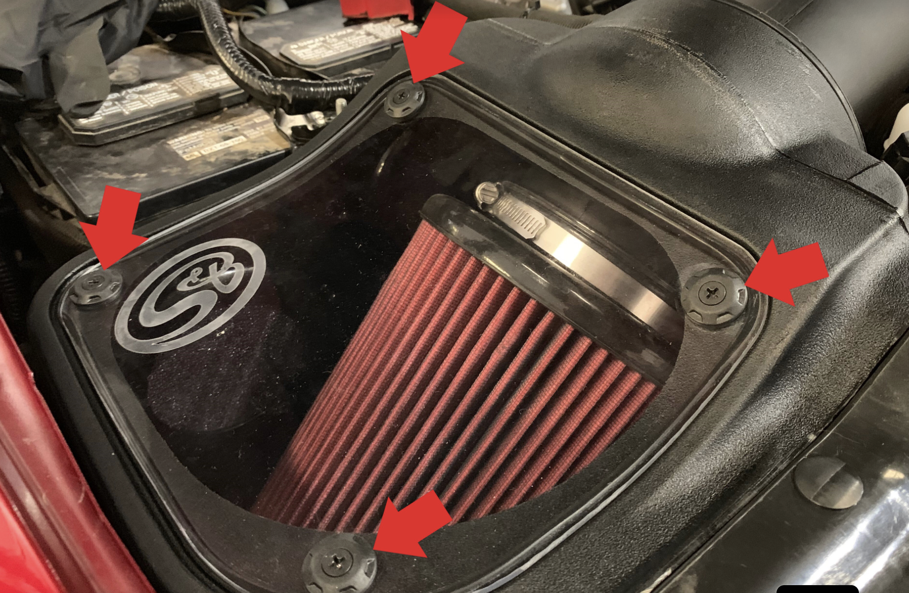
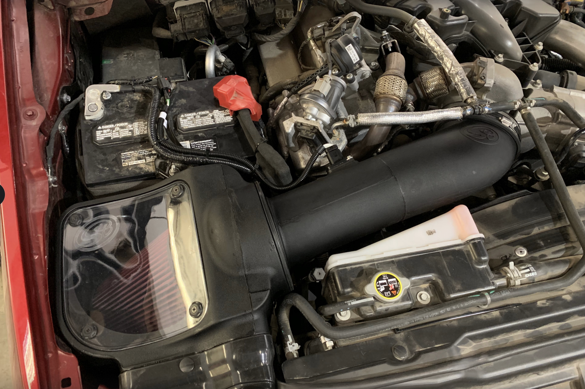
⦁ Intake Tube and Filter connections, Intake Box fasteners, and Battery Tray fasteners, making sure they are tight.

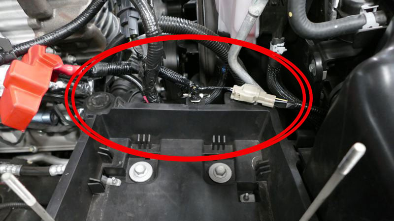
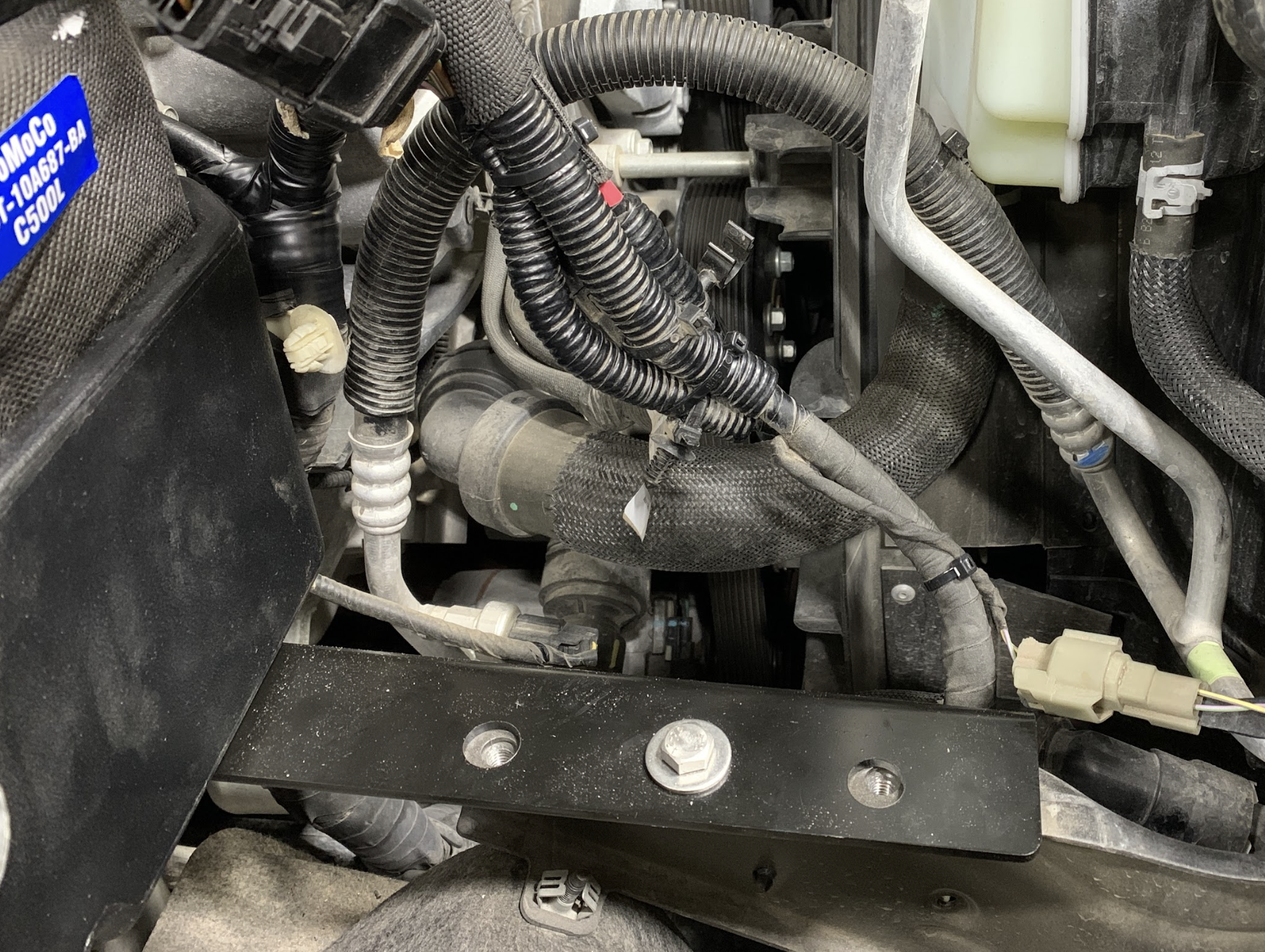
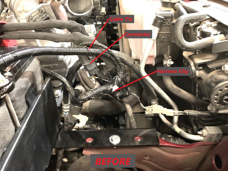
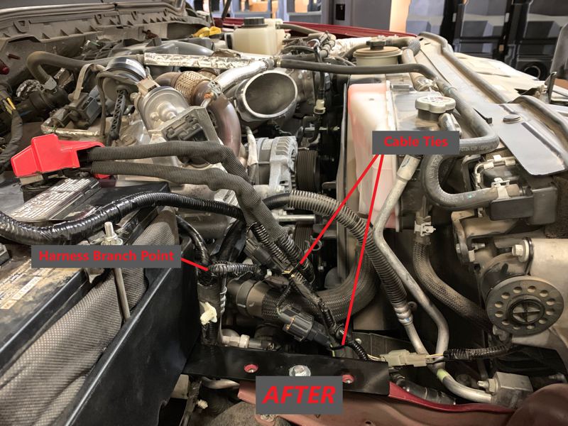
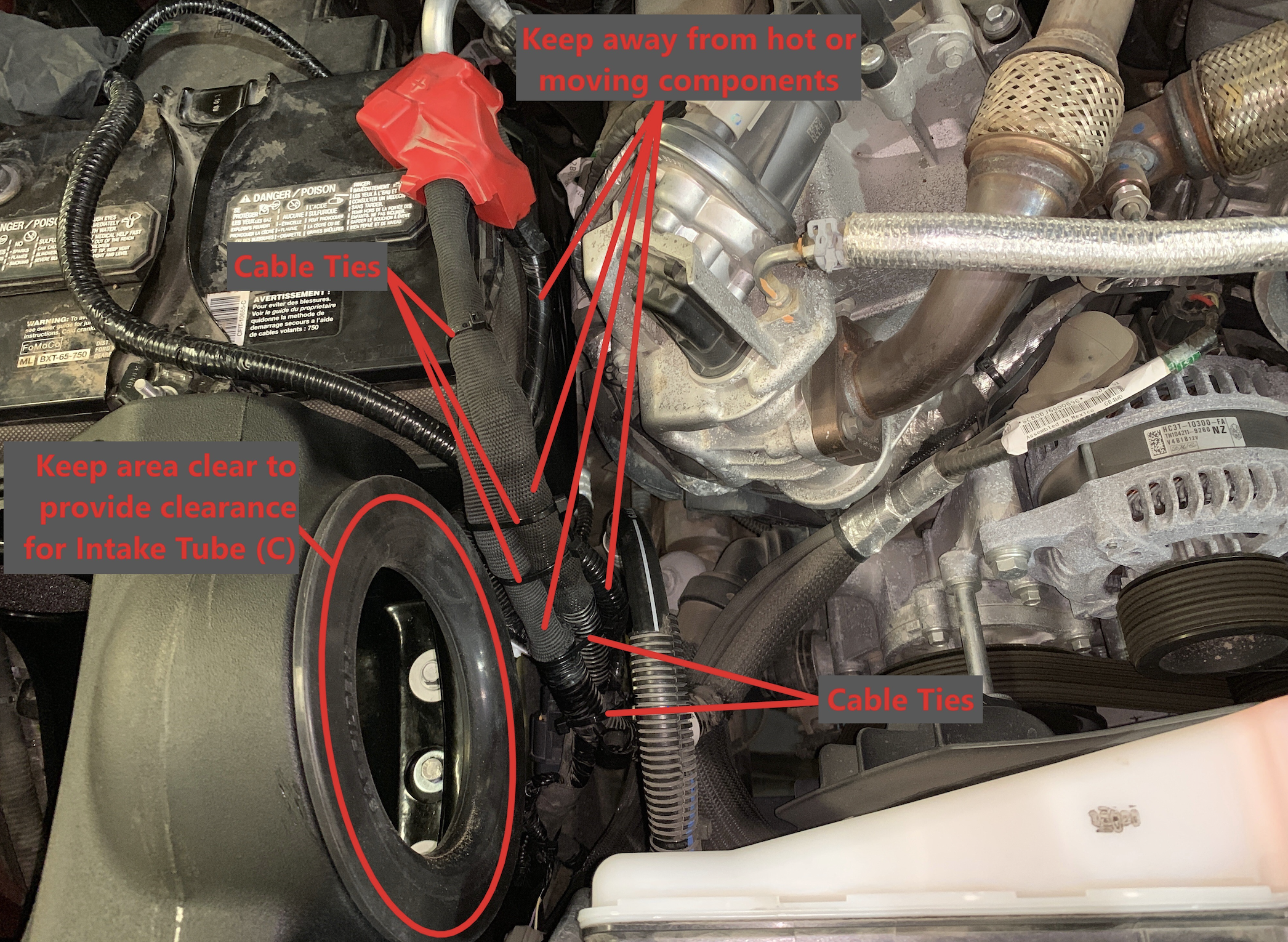
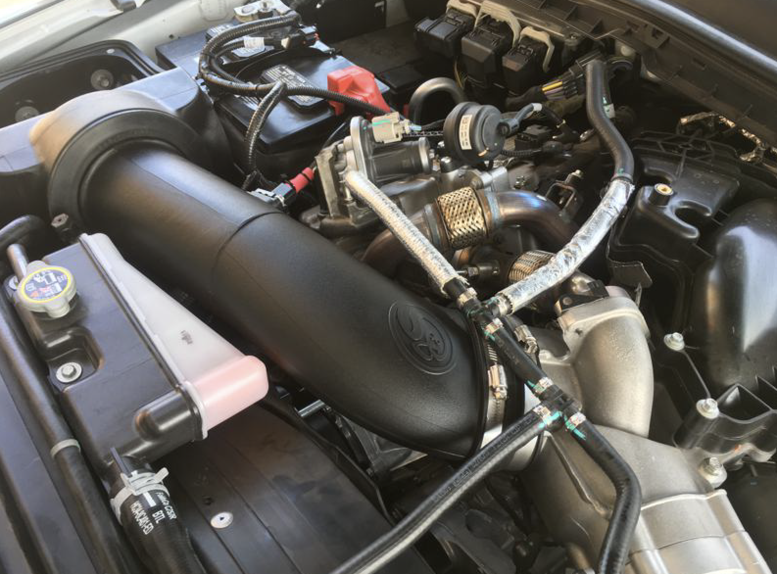
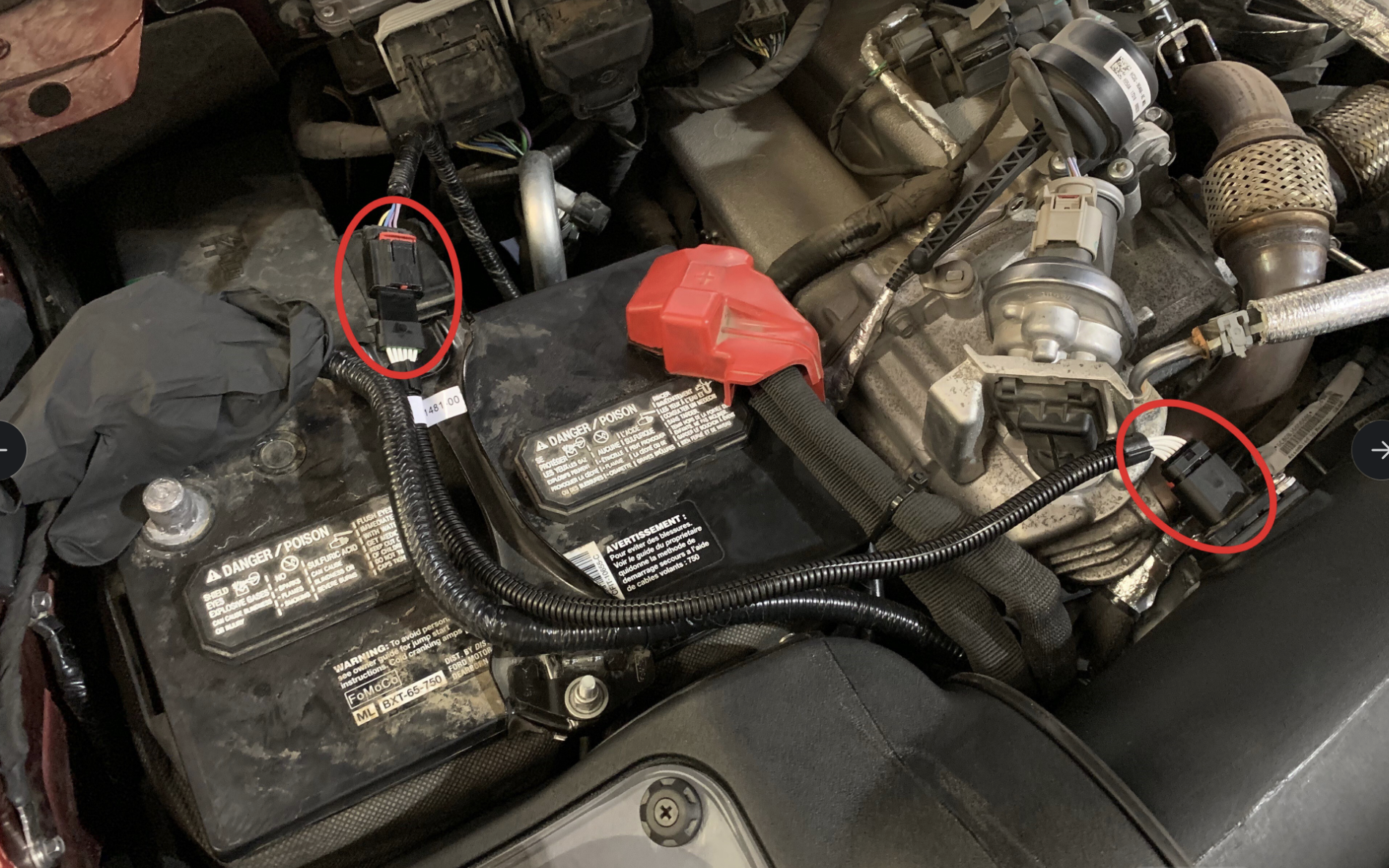
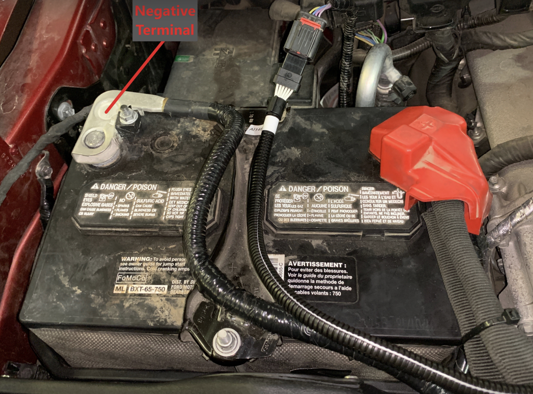
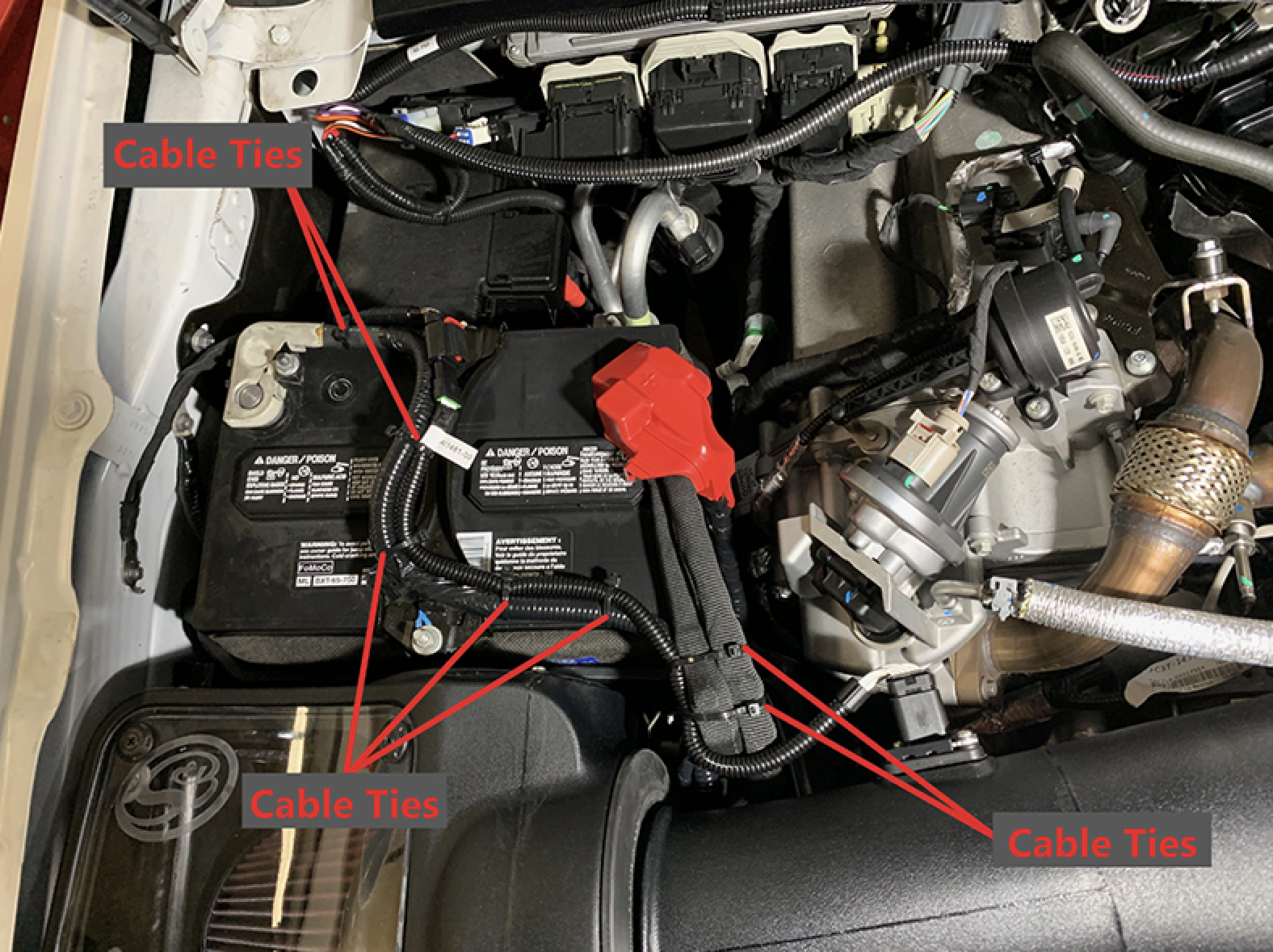
⦁ At every engine oil change service, check all electrical connections and wire harnesses moved during the installation of the intake and make sure they are secure and away from any hot or moving engine components.

⦁ At every engine oil change service, check for any signs of abrasion or wear and tear on the intake tube, box, filter, and electrical harnesses moved or near the intake and repair/replace as necessary.

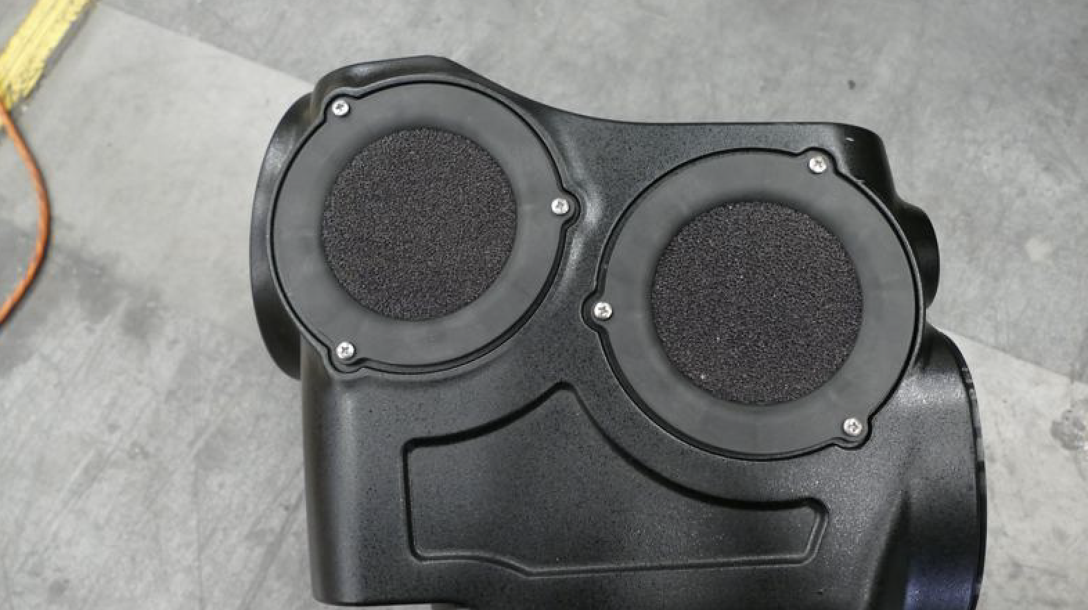
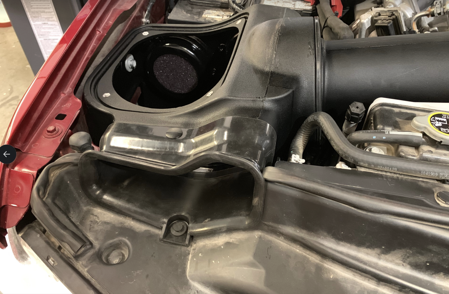
⦁ Service and check the condition of your Foam Filter (L) every time you service your air filter. Wash it with water or gently blow it off with compressed air. If it can’t be cleaned with water or compressed air, or it is torn or damaged, please replace the foam filter. HP1473-00 is the replacement foam kit that includes (1) Foam Filter, (1) Foam Retainer, and (3) Screws.

Required Tools

  • 7mm, 8mm, 10mm (Deep), 13mm Wrench/Socket
  • 5/16” Nut Driver or Flat Blade Screwdriver
  • Phillips Screwdriver
  • Panel Popper
  • Heat Gun
  • T20 Torx
  • Wire Cutters

STEP 1

With the ignition switched off and the parking brake set, Disconnect the negative battery cables on both batteries and positive battery cable on the passenger side only. 

IMPORTANT: Failure to disconnect the battery for a minimum of 2 hours may cause the Check Engine Light to illuminate upon completion of the installation or subsequent operation. DO NOT SKIP THIS STEP!

STEP 2

Remove the two nuts on the battery hold-down bracket, then remove the negative battery cable mounting tab and hold down bracket from the battery. Set the hardware aside they will be reused in Step 25.

STEP 3

Remove the battery and battery blanket from the vehicle. The battery is heavy so be extra careful when taking it out. The battery is also filled with battery acid so remember to keep it level to prevent the acid from spilling out the top.

Safety Note: Wear appropriate safety glasses and protective gloves for battery removal and installation.

STEP 4

Disengage the red locking clip, press down on the tab, then pull out to disconnect the MAF sensor harness from the MAF sensor. 


STEP 5

Disconnect the hoses attached to the stock intake tube.


STEP 6

Loosen the hose clamp connected to the stock intake box and turbo inlet then remove the stock intake tube from the vehicle.


STEP 7

Remove the two screws securing the stock intake box.


STEP 8A

Pop-out the harness clip attached to the back of the stock intake box.


STEP 8B

Lift up the stock intake box slightly to unseat the prongs from the stock grommets then remove the stock intake box from the vehicle.


STEP 9

Pop-out the stem and remove the push in rivet securing the front inlet. Set the push in rivet aside, it will be reused in Step 47.


STEP 10

Pop-out all the wire harness clips secured to the side of the battery tray.


STEP 11

Pop-out the two harness clips on the back of the battery tray.


STEP 12

Remove the four screws then remove the battery tray from the vehicle. Set the screws aside, they will be reused in Step 14 and 39.

STEP 13

Remove the two screws then remove the stock intake box bracket from the vehicle.


STEP 14

Remove the AC line clip and electrical harness clip that is attached to the frame before installing the Battery Tray Bracket (V). Make sure that the flange on the battery tray bracket is on the side facing the engine, then align the three mounting holes on the Battery Tray Bracket with the three mounting holes on the frame. Loosely install the M8 Screw (AE), Washers (X) and M8 Locknut (AF) into the center mounting hole and two stock screws from Step 12 into the bracket. This is to prevent the bracket from spinning and keeping all the mounting holes from becoming misaligned. Hand tighten the M8 Screw in the center hole to keep the Battery Tray Bracket in place but still free to rotate about the center hole. Reinsert the AC line clip and electrical harness clip into the holes provided in the side of the Battery Tray Bracket.


STEP 14 (IMAGE 2)

STEP 15

Remove the stock hold down U-bolt from the stock battery tray by first removing the two screws underneath securing the stock battery tray to the stock intake inlet.


STEP 15 (IMAGE 2)

STEP 16

Push the locking tabs and separate the stock inlet from the stock battery tray and pop out the hold down U-bolt.

STEP 16 (IMAGE 2)

STEP 17

Install the stock hold down U-bolt onto the Battery Tray (W). The stock hold down U-bolt should be installed as shown. The longer end should be closest to the longer side of the Battery Tray (W). Use a Cable Tie (AA) through the center of the battery tray to secure the hold down U-bolt.


STEP 18

Check to see if you have one or two ground cables attached to the fender as shown. Some trucks have only the primary ground and others have both the primary and secondary grounds. The primary ground is the wire attached to the negative battery terminal.


STEP 19

Remove the grounding bolt that attaches the primary ground to the fender. Set the grounding bolt aside to be used in Step 23.


STEP 20

Do not loosen the screw that holds down the secondary ground. The Battery Tray (W) is designed to have enough clearance so that the secondary ground does not touch the Battery Tray.


STEP 21

Align the holes on the Battery Tray (W) with the holes on the Battery Tray Bracket (V) and side fender wall then tighten with the M8 Screws (Y) and Washers (X). Use the longer M8 Screw (AI) for going through the long side fender boss on the Battery Tray. Make sure the Battery Tray is not touching the secondary ground.


STEP 22

Fully tighten the center mounting hole with the M8 Screw (AE), Washers (X) and M8 Locknut (AF) on the Battery Tray Bracket (V) then remove the two stock screws from the bracket to be used in Step 39B.


STEP 22 (IMAGE 2)

Image shown with two stock screws removed.

STEP 23

Reattach the factory grounding bolt removed in Step 19 to attach the primary ground to it's original threaded hole on the fender as shown. Torque to factory specifications, 106 lb-in (12 Nm). 

Note: The primary ground should be at an angle with the prong facing away from the fender as shown.

Warning: The primary ground and grounding bolt must be re-attached as specified in this step.

Failure to do so could lead to a fire.

STEP 24

Place the battery and battery blanket inside the Battery Tray (W) as shown. Be careful as the battery is heavy. The battery is also filled with battery acid so remember to keep it level to prevent the acid from spilling out the top. Pay attention to the orientation of the battery where the negative post is closest to the fender and the positive post is closest to the engine. Also, make sure the U-bolt is on the outside of the battery blanket.

Safety Note: Wear appropriate safety glasses and protective gloves for battery installation.

STEP 25

Secure the battery to the Battery Tray (W). Install the stock hold down bracket and the negative battery cable mounting tab then reinstall and tighten the nuts removed in step 2. 

STEP 26

We will now rearrange and flip the tightening mechanism on the negative battery cable terminal. This will allow the termianl to reach the battery post after the battery relocation. First completely remove the nut, screw, and wedge then pull out the metal clip then reinstall the metal clip into the longer side on the battery terminal as shown in image 2. 

STEP 26 (IMAGE 2)

STEP 27

Reinstall the tightening mechanism as shown. Open the battery terminal diameter by opening up the slit with a screwdriver so it will be easier to get the terminal fully seated onto the battery post. Do NOT install the negative battery terminal to the battery post at this time. 

STEP 27 (IMAGE 2)

STEP 28

Remove the nut on the positive terminal and disconnect the secondary cable. Set aside the nut, it will be reused in step 31. 

Note: If you have two secondary positive battery cables, disconnect both from the battery terminal.

STEP 29

Secure one end of the Battery Cable Extension (AG) to the secondary battery cable using the M6 Bolt (AB) and Flange Nut (AC). Keep the metal contacts straight. Torque the M6 Bolt and Flange Nut to 88 lb-in (9.9 Nm).

Warning!: If you have two secondary positive battery cables, install the battery cable extensions separately. Do not attempt to install two secondary positive cables with only one Battery Cable Extension (AG). This may lead to a potential fire. Also, note the orientation of the extensions when attaching them so that the free end can be stacked flat and back to back as shown in Image 2.

STEP 29 (IMAGE 2)

STEP 30A

Slide the Heat Shrink (AD) over the metal contact then shrink the tubing. Make sure there is no exposed metal or tears after shrinking the tube. Repeat the procedure and cover the Heat Shrink (AD) with another Heat Shrink (AD).

Note: If you have two secondary cables, complete the process for each secondary cable individually. Do not use one Heat Shrink (AD) for both cables.

STEP 30A (IMAGE 2)

STEP 30B

Slide the Fabric Heat Shrink (AH) and cover the entire extension including the Heat Shrink (AD). Make sure there is no exposed metal or tears after shrinking the Fabric Heat Shrink (AH).

Note: If you have two secondary battery cables, complete the process for each secondary cable individually. Do not use one Fabric Heat Shrink (AH) for both cables.

STEP 30B (IMAGE 2)

STEP 31

Reinstall the nut removed in Step 28 to secure the end of the Battery Cable Extension (AG) onto the positive battery terminal. Leave the nut loose.

Note: If you have two Battery Extension Cables (AG) installed, stack the two cables on top of each other flat, back to back as shown in Step 29, image 2, then reinstall the nut.

STEP 31 (IMAGE 2)

STEP 32A

Disconnect the harness clip and remove the cable tie on the connector shown.


STEP 32B

Temporarily place the positive battery terminal onto the positive battery post. Neatly arrange the harnesses and use Cable Ties (AA) to group them together. If you require additional slack to get the positive terminal to reach the battery post, you can extend the harness branch by removing some of the electrical tape and moving the branch point down. Use new electrical tape to cover the wires and cables of both branches individually to replace the removed electrical tape. Afterwards, remove the positive terminal from the battery post.


STEP 33

Install the Tube Seal (B) into the intake box (A)

Note: For information on servicing the Foam Filter refer to the “Periodically Check the Following” section in the beginning of the Install Instructions.

STEP 34

Install the foam filter (L) and foam retainer (M) onto the intake box (A) with the M4 Screws (N) 

STEP 35

Install the Box Inlet (J) onto the Intake Box (A) with the Plastic Rivets (U). Squeeze the plastic rivets together so they interlock into place and hold the Inlet to the Box.


STEP 36

Determine if you want to install the Box Plug Assembly with Foam (K) onto the Intake Box (A). For optimal performance, we recommend that the intake be used without the plug except in conditions of extreme heat.

Image shown with box plug installed.

STEP 36 (IMAGE 2)

Image shown with box plug uninstalled.

STEP 37

Press the Grommets (Q) into the side of the Intake Box (A).


STEP 38

Place the Intake Box (A) into the truck.  


STEP 39A

Align the mounting holes on the side fender wall and the bracket then carefully install the two stock screws removed in Step 12 making sure that the Grommets (Q) do not fall off the Intake Box (A). Leave the screws loose. Some adjustments may be needed to get the other mounting holes to line up.

STEP 39B

Install the other two stock screws and secure the bottom of the Intake Box (1). Fully tighten all four screws in Step 39A and 39B.

STEP 40

Slightly bend the AC service port so that the center of the cap lines up with the seam of the coolant reservoir as shown. This will give clearance to install the Intake Tube (C).


STEP 41

Install the positive terminal on the positive battery post. Remove the terminal clamp nut assembly and rotate it to the other side of the terminal as shown by the white arrow. Moving the terminal clamp nut will allow the positive cables and extensions to be as close as possible to the side of the battery. Now position the terminal so that the battery cables and Battery Cable Extention(s) (AG) are as close as possible to the side of the battery so that the cables do not come in contact with any hot components or moving parts. Torque the terminal clamp nut to factory specifications, 80 lb-in (9 Nm). Torque the battery cable nut to factory specifications, 80 lb-in (9 Nm).


STEP 41 (IMAGE 2)

STEP 42

Place the positive terminal cover over the positive terminal and verify that the battery cables and extensions are as close as possible to the side of the battery tray. Also make sure that the cables and extensions are away from the center of the filter opening on the Intake Box (A) to provide clearance for the Intake Tube (C). Use Cable Ties (AA) to group the wires/harness and secure them away from any hot or moving engine components that could potentially rub and damage the cables or wires.


STEP 43

Carefully remove the MAF sensor from the stock intake tube and install it onto the Intake Tube (C) with the #8-32 Screws (T), MAF Pad (S) and MAF Gasket (R). Make sure the MAF Gasket (R) is between the MAF Pad (S) and the Intake Tube (C). Also make sure that the FoMoCo Logo on the MAF Sensor is on the side closest to the round end of the Intake Tube as shown.


STEP 44

Slide the Coupler (O) over the Intake Tube (C) with the two #72 Hose Clamps (P) up to the edge of the tube. This will give you the needed clearance during the installation. Leave the Hose Clamps loose.


STEP 45

Insert the intake tube (C) into the intake box (A) at the angle showed below.

STEP 46

Rotate the intake tube and then slide the coupler (O) over the turbo inlet. The radiator hose will be sitting on top og the coupler so position the hose clamp screws away from the hoses then tighten both #72 Hoses Clamps (P)

STEP 47

Secure the box inlet (J) with the push rivet removed in step 9. 

STEP 48

Install the air filter (D) and #72 hose clamp (E) onto the intake tube (C). Tighten the hose clamp.

STEP 49

Press the lid seal (F) into the groove on top of the intake box (A) 

STEP 50

Peel off the protective covering on both sides of the Clear Lid (G).

STEP 51

Place the clear lid (G) on top of the intake box (A) and secure with the 10-24 screws (I) and lid washers (H).

STEP 52

Install one end of the MAF harness extension (Z) into the stock MAF harness and the other end into the sensor. Make sure to engage both red locking clips. 

STEP 53

Install the negative battery terminal on to the negative battery post on the passenger's side as shown. Tighten and torque the terminal clamp nut to factory specification, 80 lb-in (9 Nm).


STEP 54

Group together any loose wires/harness such as the MAF Harness Extension (Z) and secure them away from any hot components and moving parts. Use Cable Ties (AA) to neatly secure them. 

STEP 55

Inspect your installation, make sure the kit is properly positioned and all fasteners and hose clamps are secured. Keep all stock parts in case you would ever need to reinstall the stock intake assembly. Affix the ID label near the intake kit. If you are an installer, give the owner the QR code for the Installation Instructions so that he/she is aware of the "Periodically Check the Following" procedures given in the beginning of the Instructions. The Installation is now complete.