Install Instructions for 75-5099

Before You Start

This intake kit may not fit with the following Aftermarket Parts installed:

Body Lift or Lowering Kit

Custom Hood

Aftermarket turbocharger


  • Please read the entire product guide before proceeding.
  • Ensure all parts are present.
  • If you are missing any of the components, call our customer support at (909) 947-0015.
  • Do not work on your vehicle while the engine is hot.
  • Make sure the engine is turned off and the vehicle is in Park or the Parking Brake is set.


Required Tools

  • Ratchet/Wrench
  • 10mm, 5/16” Socket
  • 11mm Wrench
  • T30 Torx Wrench
  • T25 Torx Wrench
  • Pliers
  • Phillips Screwdriver

STEP 1

With the ignition switched off and the parking brake set, disconnect the negative battery cable and cover the terminal with proper insulation.

IMPORTANT: Failure to disconnect the battery for a minimum of 2 hours may cause the Check Engine Light to illuminate upon completion of the installation or subsequent operation. DO NOT SKIP THIS STEP!

STEP 2

Unlatch the tab on the MAF sensor and remove the sensor


STEP 3

Remove the vacuum line from the stock airbox


STEP 4

Remove the inlet scoop cover


STEP 5

Remove the secondary piece of the inlet scoop


STEP 6

Unscrew the bolt holding down the stock airbox and loosen the hose clamp at the throttle body connection


STEP 7

Lift up and remove the stock intake system


STEP 8A

Remove the screws securing the inlet scoop and remove the inlet scoop.


STEP 8B

...continued from Step 8a.


STEP 9

Install the Tube Seal (9) on the Airbox (8)


STEP 10

Install the Inlet Seal (14) on the Airbox (8)


STEP 11

Install the provided Grommets (15) on the Airbox (8)


STEP 12

Insert the Airbox Mounting Spacer (16) and Silicone Hose (17) into the corner Grommet (15)


STEP 13A

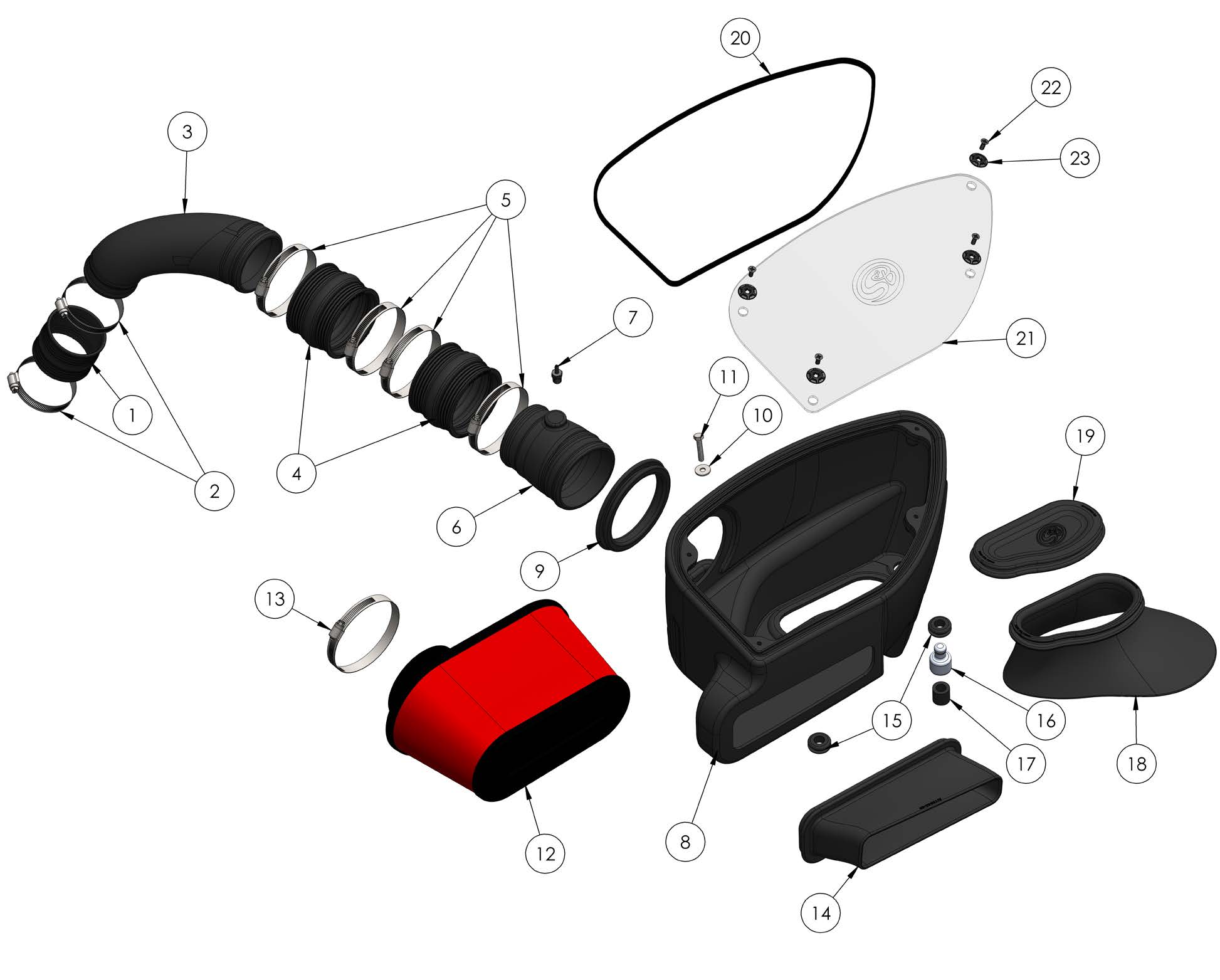
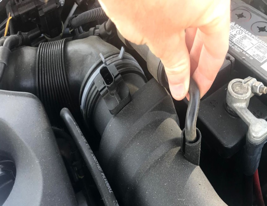
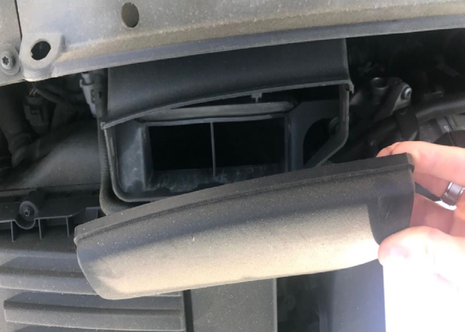
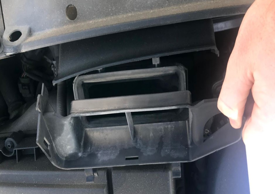
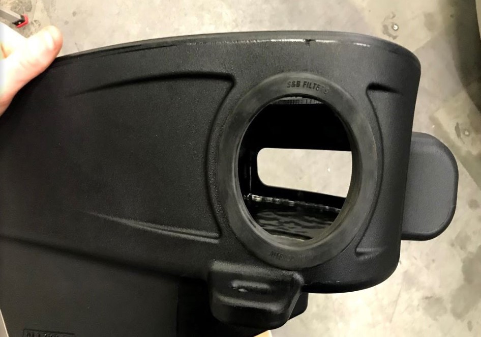
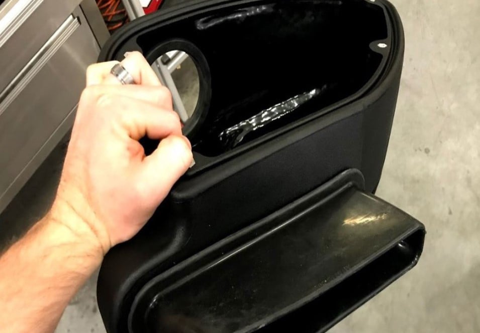
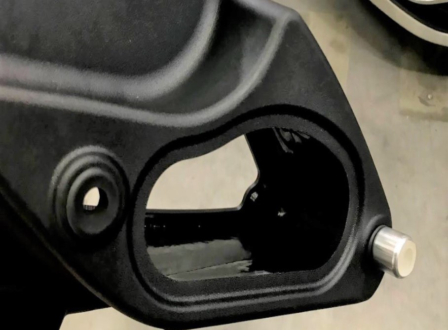
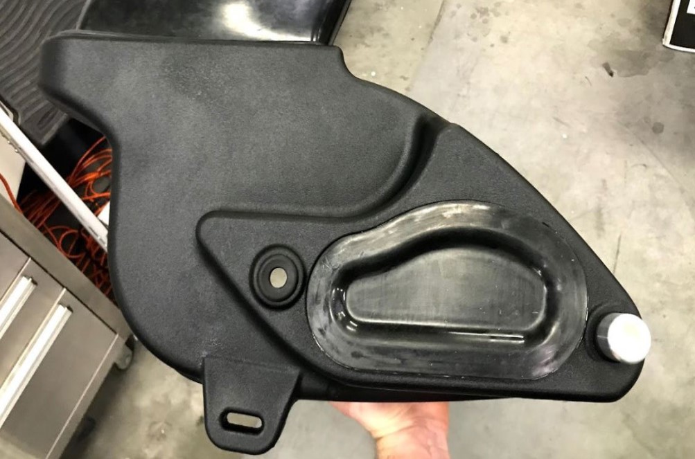
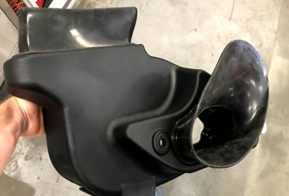
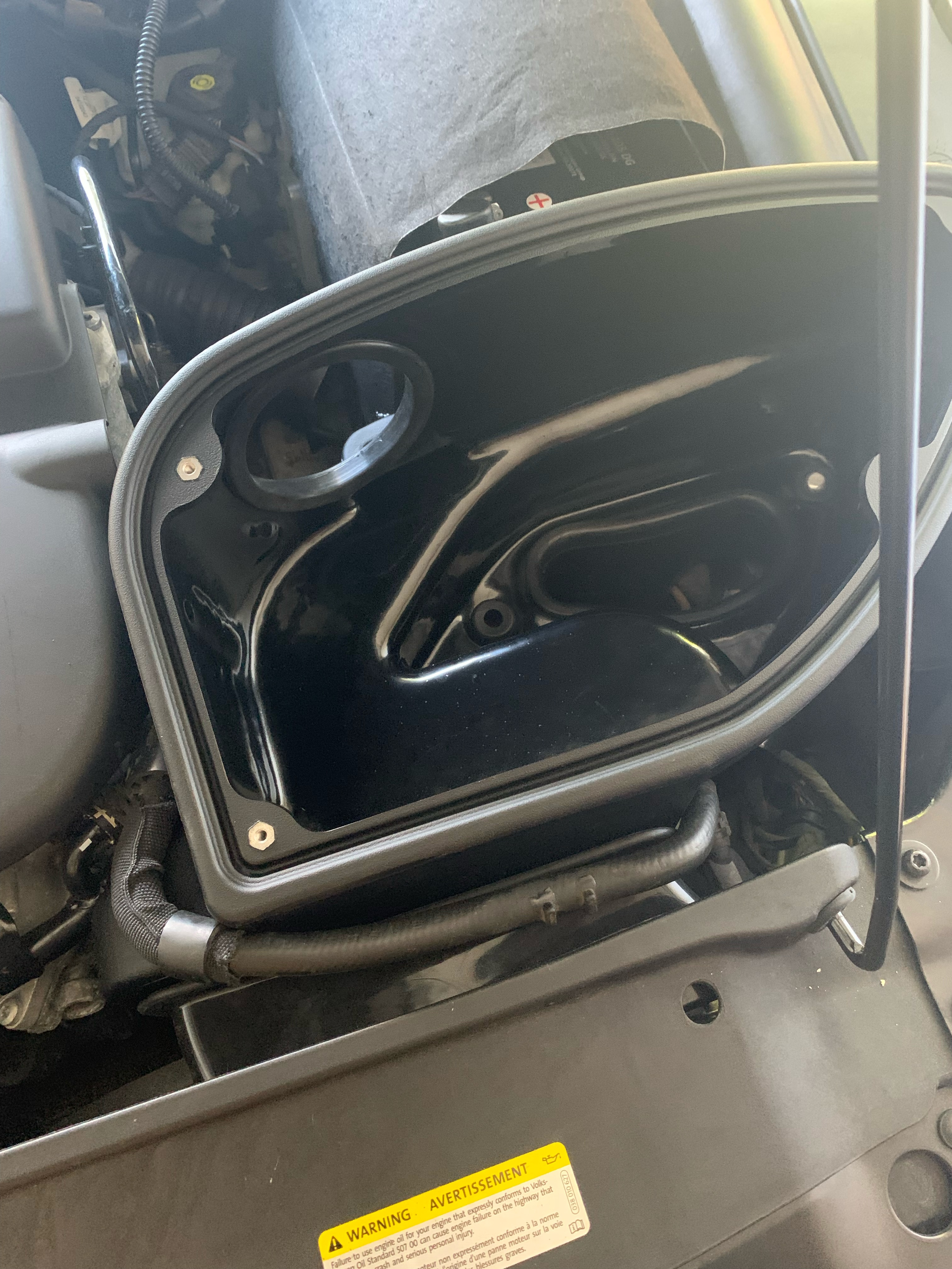
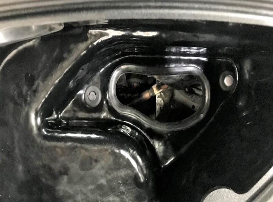
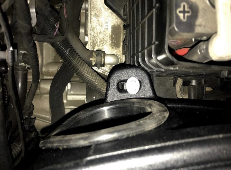
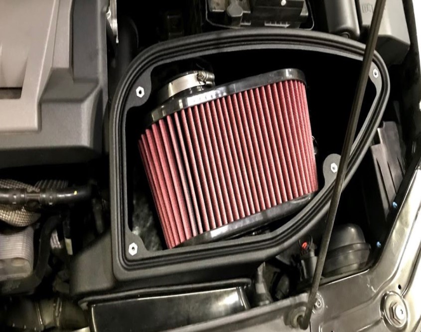
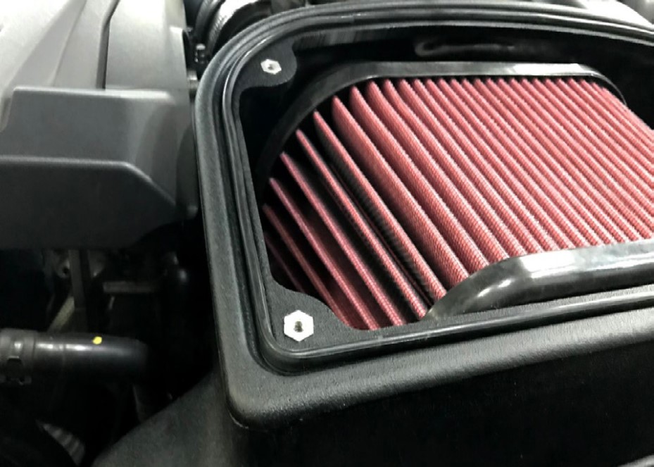
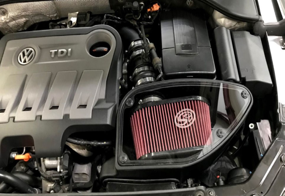
Determine if you want to install the Box Plug (19) on the Airbox (8) or install the Base Scoop (18) on the Airbox (8). If the Box Plug (19) is desired, simply install the Box Plug (19) in the opening on the box, otherwise, install the Base Scoop (18 ) on the opening on the box.

When should I install the optional box plug?
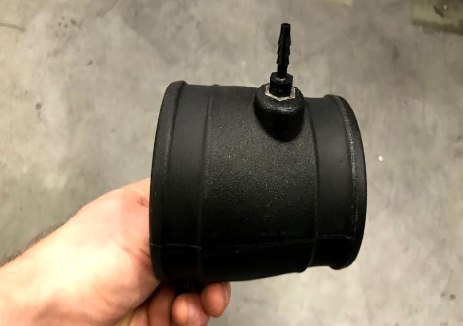
Depending on your airflow requirements, you can gain increased airflow by removing the optional box plug. We recommend removing the plug if your vehicle has other performance upgrades. Keep in mind that you are exposing you filter to more dirt and bugs therefore your filter will need to be serviced/changed more often. We recommend in warmer temperatures to keep the plug installed to keep out excess engine heat.

STEP 13B

...continued from Step 13a.


STEP 14A

Install the Airbox (8) on the pegs in the engine bay. Make sure to adjust the Base Scoop (18) as needed and adjust the Inlet Seal (14) so that it surrounds the inlet area. You will need to position the coolant hose around the front of the air box as shown below in the picture to the right. 


STEP 14B

...continued from Step 14a.


STEP 15

Secure the Airbox (8) to the engine bay using the provided Screw (11) and Washer (10)


STEP 16

Install the Hose Barb (7) on Intake Tube #1 (6). Hand tighten first and then secure by the wrench.


STEP 17

Place the Air Filter (12) in the Airbox (8)


STEP 18

Install the Coupler (4) on Intake Tube #1 (6) using the provided Hose Clamp (5)


STEP 19

Install the OEM MAF Sensor Housing on the Coupler (4) using the provided Hose Clamp (5)


STEP 20

Install the second Coupler (4) on the OEM MAF Sensor using the provided Hose Clamp (5)


STEP 21

Install the Intake Tube #2 (3) on the second Coupler (4) using the provided Hose Clamp (5). Do not fully tighten to allow for adjustment later.


STEP 22

Install the Coupler (1) on the throttle body using the provided Hose Clamp (2)


STEP 23

Install the assembled Intake Tube #1 (6), OEM MAF Sensor, and Intake Tube #2 (3) by inserting it through the Tube Seal (9) and Airbox (8). Connect Intake Tube #1 (6) and the Air Filter (12) using the provided Hose Clamp (13). Connect Intake Tube #2 (3) and the Coupler (1) using the provided Hose Clamp (2). Make sure all clamps are tightened.


STEP 24

Reconnect the electrical harness to the MAF sensor, and connect the vacuum hose to the Hose Barb (7)


STEP 25

Install the Lid Seal (20) on the Airbox (8)


STEP 26

Pre-assemble the Screws (22) and Washers (23) for the Clear Lid (21)


STEP 27

Remove paper from the Clear Lid (21)


STEP 28

Install the Clear Lid (21) on the Airbox (8) using the provided Screws (22) and Washers (23)


STEP 29

Reconnect the negative battery cable


STEP 30

Inspect your installation, make sure the kit is properly positioned and all fasteners are secure. Keep all stock parts in case you would ever need to reinstall the stock intake assembly. Affix the ID label near the intake kit. The installation is now complete