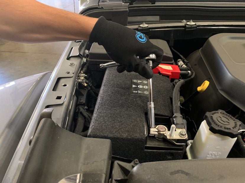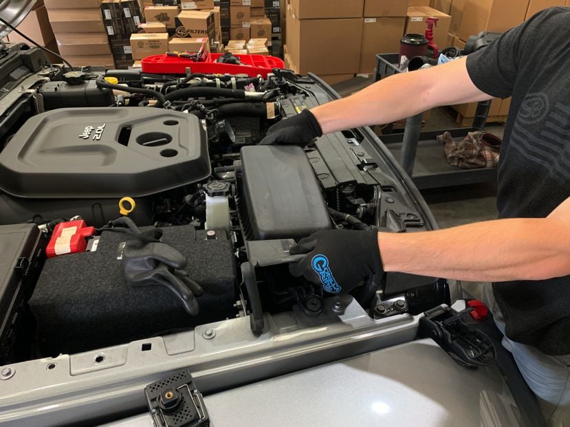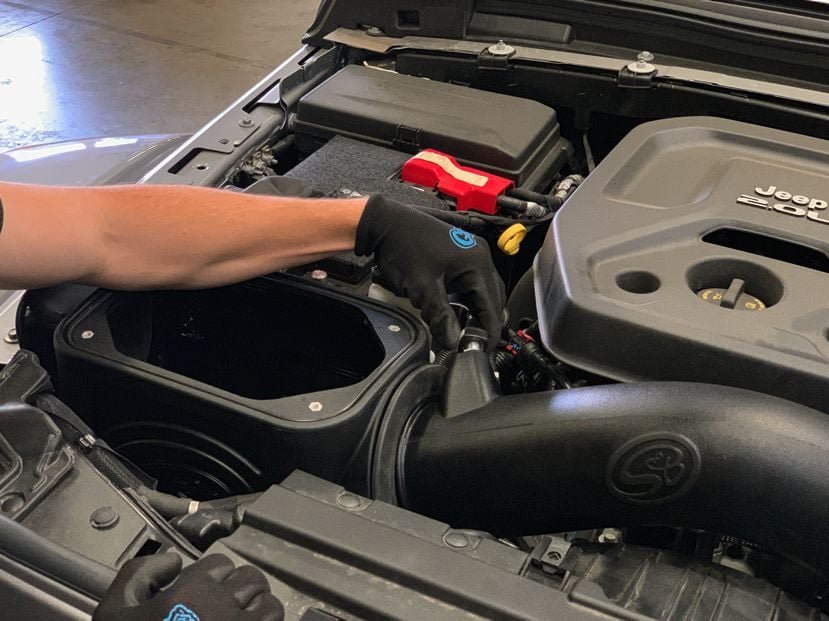
STEP 1
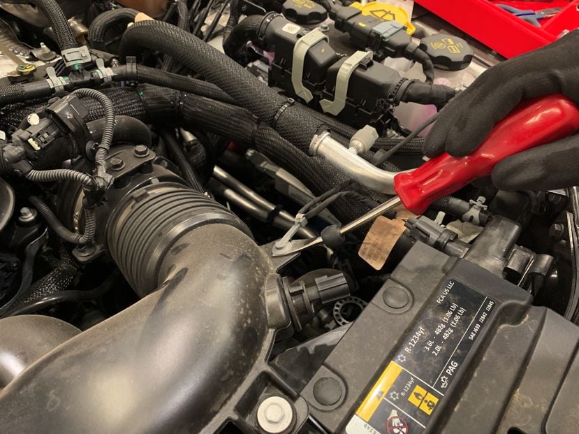
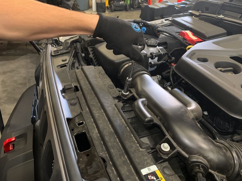
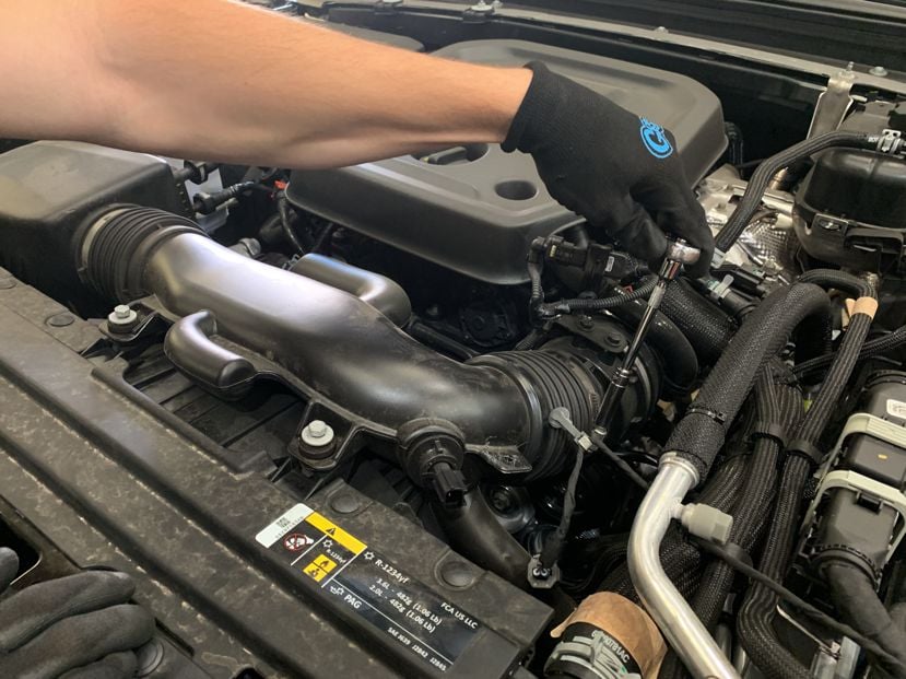
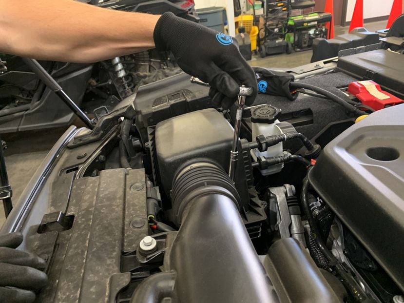
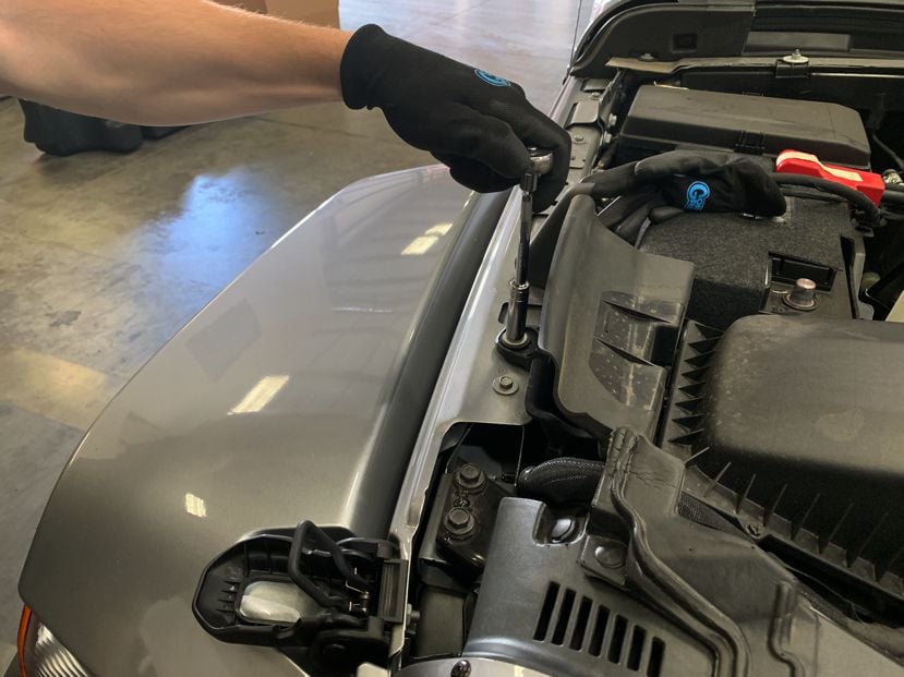
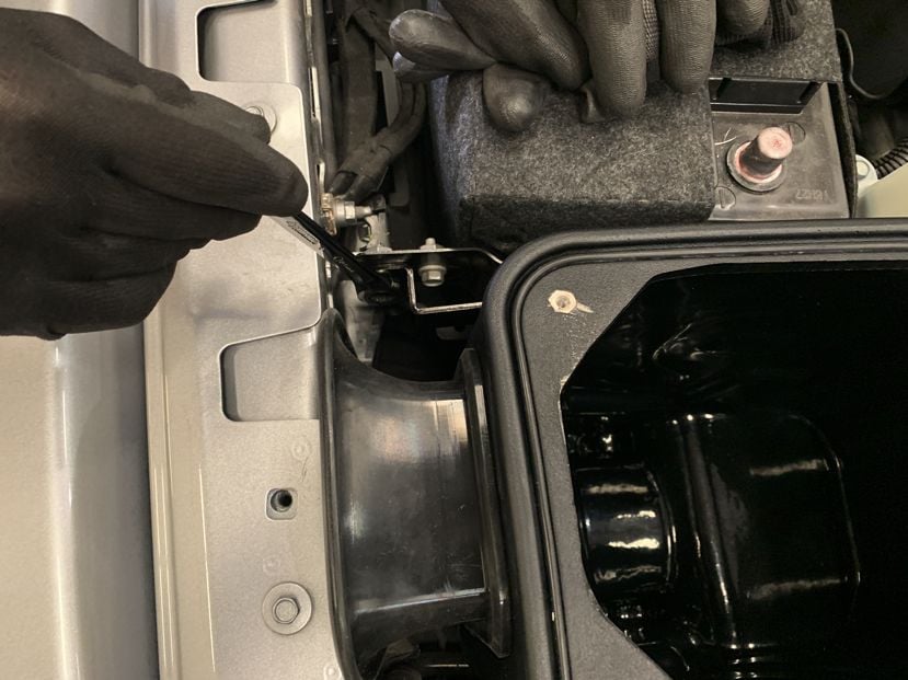
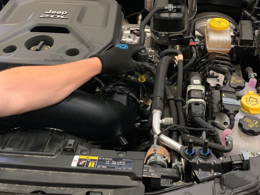
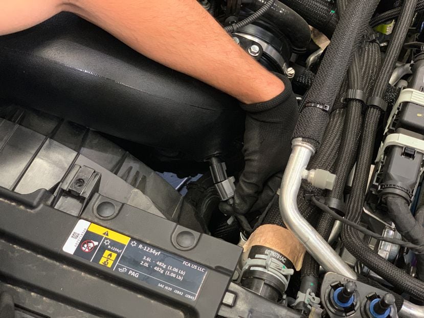
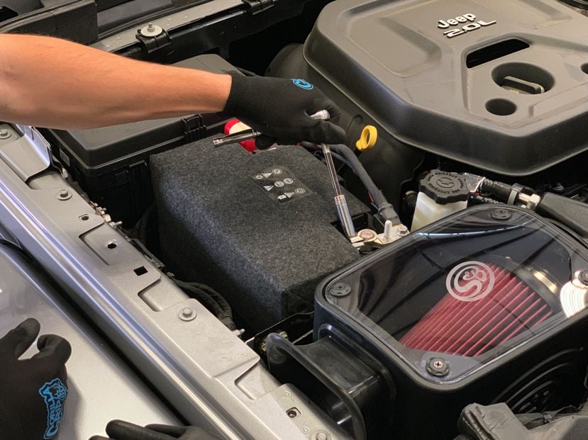
With the ignition switched off and the parking brake set. Disconnect the negative battery cable on the passenger side.
IMPORTANT: Failure to disconnect the battery for a minimum of 2 hours may cause the Check Engine Light to illuminate upon completion of the installation or subsequent operation.
DO NOT SKIP THIS STEP!
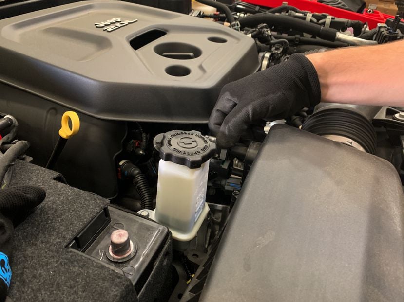
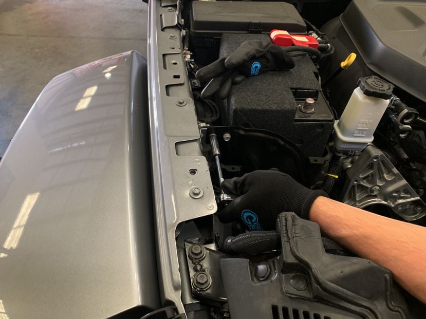
Warning!: The Jeep JL’s have a smaller secondary battery underneath the main battery and fuse box. This battery will remain connected during the install so keep in mind that the wires are still live when working on your vehicle.
Tools Required: Ratchet, 10mm Socket/Wrench