Install Instructions for 75-5130

Before You Start

Please read the entire product guide before proceeding. Ensure all parts are present. If you are missing any of the components, call our customer support at (909) 947-0015. Do not work on your vehicle while the engine is hot. Make sure the engine is turned off and the vehicle is in Park or the Parking Brake is set.

This intake kit may not fit with the following Aftermarket Parts installed: Body Lift or Lowering Kit or Custom Hoods.

Required Tools

8mm, 10mm, 13mm Wrench & Socket, Pin Removal Tool or Flat Blade Screwdriver, 5/16” Nut Driver or Flat Blade Screwdriver, Phillips Screwdriver, 3/16” Allen Wrench, 1 Pair of Pliers or similar tool, Teflon Tape.

Note: Approximate Install Time: 1 Hr 00 Mins.

STEP 1

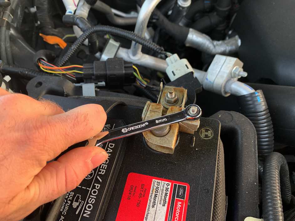
With the ignition switched off and the parking brake set, disconnect the negative battery cable on the passenger side.

IMPORTANT: Failure to disconnect the battery for a minimum of 2 hours may cause the Check Engine Light to illuminate upon completion of the installation or subsequent operation.

DO NOT SKIP THIS STEP!

Tools Required: 8mm wrench or socket.

STEP 2

Locate the Intake Air Temperature Sensor on the stock intake. Remove the wire harness from the sensor by pressing down on the tab, then pulling back on harness plug, taking care not to pull by the wires.

STEP 3

Leave the sensor installed in the factory air box cover, for now.

STEP 4

Loosen the three hose clamps on the factory intake tube.

Tools Required: 5/16” nut driver or similar tool.

STEP 5

Pull back on the bellowed portion of the intake tube, removing it from the stock airbox cover.

STEP 6

Pull the rest of the factory intake tube out by moving it to the side and lifting up.

STEP 7

Remove the factory air box cover by disconnecting the three latches that are on the side of the factory air box.

STEP 8

Lift the cover up, then out to the side.

STEP 9

Remove the factory air filter.

STEP 10

Remove 10mm nut holding down the hood sensor bracket, and move the bracket aside. This will allow access to the 13mm bolt on the factory airbox.

Tools Required: 10mm wrench or socket

STEP 11

Remove the factory air box by removing both 13mm bolts and lifting up on the box. The other connections to the box do not need to be removed to gain access to the side inlet.

Tools Required: 13mm wrench or socket

STEP 12

Once access to the side inlet is available, remove by pushing down on the tabs. Push down on the bottom tab while pulling on the inlet, partially dislodging the inlet

STEP 13

Once the inlet is partially dislodged, return to the topside of the factory air box and push down on the top tabs while pulling the inlet away from the factory air box.

Tools Required: Flat blade screwdriver or similar tool.

STEP 14

Install the S&B fender Inlet (R) by pushing in firmly, until it snaps into place.

STEP 15

After the S&B inlet is installed, lower the factory air box back down and reinstall the factory bolts. Make sure the S&B inlet (R) is pushed through the side skirt.

Tools Required: 13mm wrench or socket

STEP 16

Reinstall the hood sensor bracket.

Tools Required: 10mm wrench or socket

STEP 17

Attach coupler (P) to intake tube (K) using 2 #52 hose clamps (F). Only tighten the hose clamp on the S&B intake tube side while leaving the other hose clamp loose.

Tools Required: 5/16” nut driver or similar tool.

STEP 18

Attach coupler (O) to intake tube (K) using 2 #72 hose clamps (G). Only tighten the hose clamp on the tube side while leaving the other hose clamp loose.

Tools Required: 5/16” nut driver or similar tool.

STEP 19

Attach the #104 hose clamp (I) to the intake rubber cuff (N).

STEP 20

Install the cuff (N) onto the S&B air box cover (J) making sure that the tab on the cuff aligns with the notch on the S&B Air Box Cover.

STEP 21

Insert the intake tube (K) into the cuff. Ensure that the tube is pushed all the way to the stop hump of the tube. This will not be an air tight fit to allow for engine movement.

STEP 22

Once the tube is pushed flush against the stop hump of the tube the hose clamp (I) on the cuff can be tightened down.

Tools Required: 5/16” nut driver or similar tool.

STEP 23

Flip over the assembly and install the S&B air filter (M) and tighten the #88 hose clamp (H).

Tools Required: 5/16” nut driver or similar tool.

STEP 24

Carefully remove the Air Temperature Sensor from the factory air box lid by turning it 45 degrees counterclockwise and pulling away from the intake. Gripping the sensor may require pliers. Angling the sensor away from the plastic ramp will aid in removal.

Tools Required: pliers or similar tool.

STEP 25

Install the IAT Sensor Grommet (T) into the IAT sensor adapter plate (Q).

STEP 26

Install the IAT sensor into the grommet, aligning the tab on the sensor with the beginning of the ramped stop on the grommet, turn the sensor 45 degrees clockwise so the tab is past the end of the ramped stop.

STEP 27

Install the IAT sensor adapter plate (Q) and gasket (S) using the two 10-32 screws (D). Align the arrows to ensure proper installation.

Tools Required: #2 Phillips head screwdriver.

STEP 28

Install the Hex Plug Socket (E) into the crankcase inlet using a 3/16” Allen wrench; use Teflon tape on the threads of the plug.

Tools Required: 3/16” allen wrench.

STEP 29

The S&B intake is now ready for installation.

STEP 30A

Locate the CCV hose on the lower intake tube, highlighted with the red arrow.

STEP 30B

Disconnect the quick disconnect by rotating the tab on the quick disconnect. Removing the engine cover improves access, but is not necessary.

STEP 30B (IMAGE 2)

STEP 30C

Orient the CCV tube insert, the angled cut on the insert should be facing the turbo/firewall.

STEP 30D

Insert the CCV tube insert until the insert bottoms out against the quick disconnect.

STEP 30E

Reattach the hose and reinstall the cover, if previously removed.

STEP 30E (IMAGE 2)

STEP 31

Place the intake assembly into the stock intake box, aligning the tabs on the S&B Air Box Cover (J) into the slots on the right hand side of the factory air box. Once the tabs are in the slots, lower the intake assembly into place.

STEP 32

Lower the complete assembly and make sure the S&B AIr Box Cover (J) sits inside the factory air box slots. Proper installation into the slots will reduce movement.

STEP 33

Insert the bottom turbo inlet tube into the bottom tube coupler (O). After the tube is pushed up to the stop, tighten the #72 hose clamp (G).

Tools Required: 5/16” nut driver or similar tool.

STEP 34

Insert the top turbo inlet tube completely and tighten the #56 hose clamp (F).

Tools Required: 5/16” nut driver or similar tool.

STEP 35

After all the hose clamps are tightened connect the three latches on the side of the intake box.

STEP 36

Plug the harness into the air temperature sensor under the intake tube. Press in firmly until it locks.

STEP 37

Remove the protective covering from the S&B Filters Clear Lid (L)

STEP 38

Secure the air box lid (L) using the provided hardware (B & C).

STEP 39

Reconnect the battery. Inspect your installation, make sure the kit is properly positioned and all fasteners are secure.