Install Instructions for 75-5132/75-5132D

Before You Start


VEHILCE FITMENT:  2019-2024 6.7L Cummins, Dodge/Ram, 2500/3500

DEVICE NAME: COLD AIR INTAKE 


Please read the entire product guide before proceeding. Ensure all parts are present. If you are missing any of the components, call our customer support at (909) 947-0015. Do not work on your vehicle while the engine is hot. Make sure the engine is turned off and the vehicle is in Park or the Parking Brake is set.

Note: This intake kit may not fit with the following Aftermarket Parts installed: Body Lift or Lowering Kit Custom Hood Intercooler or Turbo upgrades.

Required Tools

Flathead screwdriver
T20 Torx bit and driver
10mm, 11mm, Combination of Wrench or Socket and Driver
5/16” Nut Driver or socket (possible extension needed)
Panel Popper
Step Stool (Optional)

Note: Approximate Install Time: 1 Hr 00 Mins.

NOTE BEFORE INSTALLATION:

Please allow for a one hour waiting period after shutting the engine off before installing this S&B cold air intake. This will have the best immediate performance while avoiding sensor disconnect codes related to disconnecting the sensors too soon after the engine is shut off.
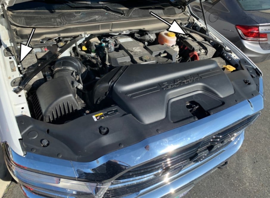
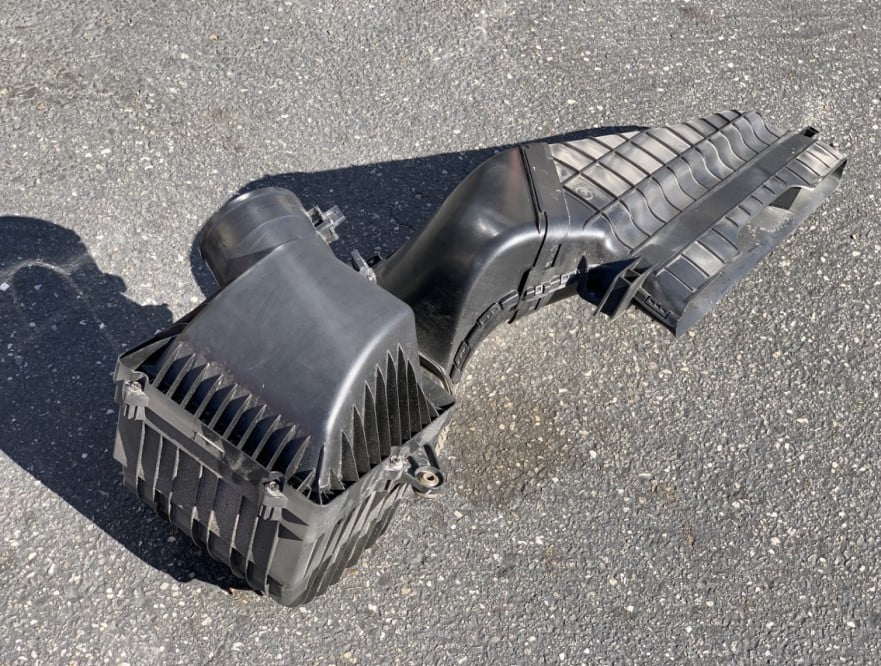
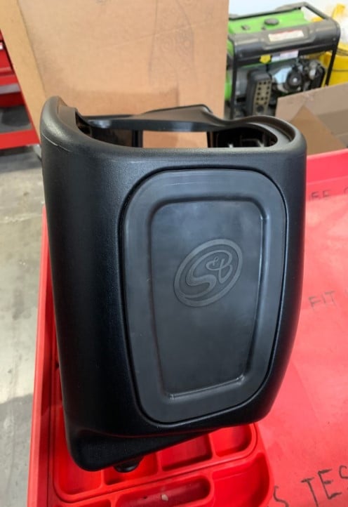
STEP 1

After waiting for one hour with the engine turned off, open the hood and begin installation.


IMPORTANT: Failure to wait for a one hour period may cause the CEL to illuminate upon completion of the installation and subsequent operation.

DO NOT SKIP THIS STEP!

STEP 2

Remove the panel push-in rivets attaching the air scoop cover. There are 12 in total. Be sure to remove the two in the rear of the scoop cover connected to the factory scoop. A step stool may be required to reach.

STEP 2A

Use a flathead screwdriver prying under the locating pins to separate the locking pin and base.

Note: Collect these to be used later for re-installation.

STEP 3

Lift-up the factory air scoop cover and remove it from the vehicle. Set it to the side, to be re-installed later

STEP 4

Remove the 2 bolts attaching the factory air scoop to the vehicle using a 10mm driver or socket. Collect these bolts and set them to the side, to be re-installed later.

STEP 5

Disconnect the Intake Air Temp (IAT) and Mass Air Flow (MAF) Sensors from the stock airbox.

For easier access to disconnect the sensors, remove the Torx screws using a T20 Torx driver.

STEP 5A

To remove the IAT sensor press down on the grey tab and pull to release.

STEP 5B

To remove the MAF sensor use a flathead screwdriver to pry off the tab cover

STEP 5C

Pull out the grey tab. Press down on the grey tab and pull to release.

STEP 6

Using a panel popper remove the panel rivets securing the electrical harness connected to the factory airbox and air scoop locations

STEP 7

Using a 5/16” driver or socket, loosen the hose clamp on the factory tube connected at the turbo inlet. Access can be a challenge. If necessary use a socket extension to access the worm drive of the hose clamp.

STEP 8

Firmly Lift up and remove the entire factory intake assembly from the grommets of the vehicle. Set the assembly to the side.

Important Note:

If you were provided sensor gaskets with your intake kit, please proceed to step 9B. 

If your kit did not come with sensor gaskets continue to Step 9A. 

Step 9A

Install the IAT and MAF Sensor to the new tube and install using the 3 provided self-tapping screws. 

Step 9B (If sensor gaskets were provided)

Assemble onto the S&B Tube the gaskets and sensor pads for the IAT and MAF. Secure the sensors with the #8-32 pan head screws provided using a Phillips screwdriver.

STEP 10

Push the S&B Silicone Coupler (U) onto the S&B tube (L) and secure with #72 Hose Clamp (T) using a 5/16” driver or socket.

STEP 11

Attach the mounting bracket (G) to S&B airbox (J) by securing the ¼”-20 screws (D) and ¼” washers (E) using an 11mm socket or driver.

STEP 11 A

The screws and washers are mounted from the interior of the airbox through the holes to the bracket on the exterior of the airbox.

STEP 12

Install the silicone tube seal (K) onto the airbox (J).

STEP 13

Insert the Air Filter (C) into the Airbox (J).

STEP 14

Attach the tube (J) to the filter flange and slightly tighten the #88 hose clamp (I) using a 5/16” driver or socket. Allow the tube to be able to rotate for later in the installation.

STEP 15

Install the silicone scoop seal (V) onto the S&B airbox (J).

STEP 16

Decide to install the optional S&B silicone plug (F) onto the S&B Airbox or leave out.

STEP 17

Install the provided replacement S&B mounting grommets (H) onto the bottom of the S&B Airbox and mounting bracket.

STEP 18

Remove the top portion of the scoop by prying the tabs to the sides of the scoop from the factory intake assembly using a flathead screwdriver.

STEP 19

Align the factory scoop with the S&B Airbox (J). Push the factory scoop over the S&B scoop seal (V).

STEP 20

Drop the Complete S&B Cold Air Intake assembly and factory scoop into the vehicle. Lining up grommets, Push in firmly onto the vehicles factory mounting locations

STEP 21

Line up the #72 hose clamp (T) over the turbo body and push on the coupler at the turbo. Tighten the hose clamp using a 5/16” driver or socket (possible socket extension).

STEP 22

Lineup factory scoop into the factory position and tighten the bolts, removed in step 4, using a 10mm socket or driver.

STEP 23

Reconnect MAF and IAT sensor harnesses onto the S&B tube

STEP 24

Re-attach the scoop cover using the factory plastic rivets

STEP 25

Remove the protective covering from S&B clear lid (A), be sure to remove the covering from inside the S&B logo!

STEP 26

Install the Silicone Snap-in Lid seal (B) onto the S&B Clear Lid (A). Line up the lid notch feature on the lid into the silicone part underneath the pull tab so it is oriented in the seal properly. Continue to pull the seal over the edges of the lid until the lid is securely completely within the silicone snap-in seal. the mating feature on the silicone part is underneath the pull tab.

STEP 27

Install the S&B Snap-in Clear Lid onto the S&B Air box by inserting one corner or edge of the seal fully first, then work around the lid by pressing on until each section has snapped in.

How to install snap-in lid

STEP 28

Inspect your installation, making sure the kit is properly positioned and all fasteners are secure. Keep all stock parts in case you would ever need to reinstall the stock intake assembly. The installation is now complete.

MAF SENSOR REVERSAL: OVERVIEW

This intake relocates the MAF sensor to a section of the tube to read the correct values for airflow. That relocation can result in the MAF connectors braided split loom touching the intakes' silicone tube seal. While it will not damage the wiring in this configuration, some customers may prefer the split loom to have more clearance. The 90 degree shielding over the MAF sensor connector can be reversed to change the direction of the split loom. The following steps will illustrate how to reverse the MAF connector wiring shield so that the split loom does not touch the silicone tube seal.

STEP 1

With the engine off, unplug the MAF sensor connector from the MAF sensor. Locate the two snapping points on the wiring shield. Push in on the tabs to unlock the wiring shield.

STEP 2

Carefully pry open the wiring shield with a small screwdriver.

STEP 3

Remove the shield from the connector and reverse it so that the wires are routed away from the silicone tube seal.

FINAL STEP

Reinstall the wiring shield over the MAF sensor connector and reconnect into the MAF sensor.

CARB EO LABEL

Please affix the included CARB-approved EO label in an area under the hood. We recommend placing it on the radiator shroud, or the underside of the vehicle's hood near the S&B product.