STEP 1
With the ignition switched off and the parking brake set, open the hood and disconnect the negative battery cable on the driver’s side of the engine.
Please read the entire product guide before proceeding. Ensure all parts are present. If you are missing any of the components, call our customer support at (909) 947-0015. Do not work on your vehicle while the engine is hot. Make sure the engine is turned off and the vehicle is in Park or the Parking Brake is set.
Note: This intake kit may not fit with the following Aftermarket Parts installed: Body Lift or Lowering Kit, Custom Hood, Intercooler or Turbo upgrade.
Flathead screwdriver, 10mm, 11mm, Wrench or Socket and Driver, 5/16” Nut Driver or socket (possible extension needed), Silicone Spray Lubricant (Optional), Step Stool (Optional).
Note: Approximate Install Time: 1 Hr 00 Mins.


With the ignition switched off and the parking brake set, open the hood and disconnect the negative battery cable on the driver’s side of the engine.

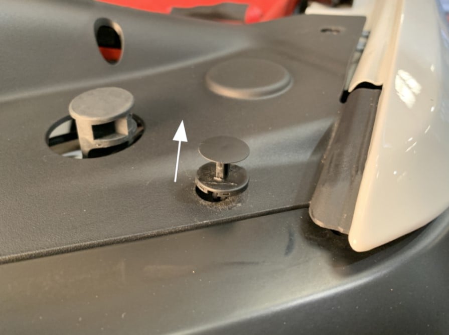
Remove the panel push-in rivets attaching the air scoop cover with a flathead screwdriver by prying under the locating pins. Note: Collect these to be used later for re-installation. There are 12 in total. Please be sure to remove the two in the rear of the scoop cover connected to the factory scoop. A step stool may be required to reach.
LIft up the factory air scoop cover and remove it from the vehicle. Set it to the side, to be re-installed later.

Remove the 2 bolts attaching the factory air scoop to the vehicle using a 10mm socket and driver. Collect these bolts and set them to the side, to be re-installed later.

Uninstall the factory engine cover by lifting up and pulling towards the front of the vehicle.

Disconnect the crankcase vent tube by pulling the hose firmly away from the factory air tube.

Remove the IAT sensor from the factory tube by twisting counterclockwise then pulling out of the factory tube, if it seized spray silicone lubricant to aid in its release

Using a 5/16” driver or socket, loosen the hose clamp on the factory tube connected at the throttle body.

Using a panel popper remove the panel rivets securing the electrical harness connected to the factory airbox and air scoop locations

Firmly Lift up and remove the entire factory intake assembly from the grommets of the vehicle. Set the assembly to the side

Install the silicone scoop seal (I) onto the S&B airbox (K)

Assemble the Silicone tube seal (L) onto the S&B Airbox (K)

Push the S&B Tube (M) through the Silicone tube seal (L)

Assemble the IAT Grommet (N) onto the S&B Tube (M)

Push the S&B Silicone Coupler (P) onto the S&B tube (M) and secure with #60 Hose Clamp (O) using a 5/16” driver or socket. You may also place the #56 hose clamp (Q) over the opposite coupler end at this time. Leave the #56 hose clamp loose at this time

Attach the mounting bracket (G) to S&B airbox (K) by securing the ¼”-20 screws (D) and ¼” washers (E) first by hand tightening

Proceed to tighten firmly using an 11mm socket or nut driver

Decide to install the optional S&B silicone plug (F) onto the S&B Airbox (K) or leave out. Box plug is recommend to be installed in extreme heat conditions where average temperatures are above 100 Degrees Fahrenheit.

Install the provided replacement S&B mounting grommets (H) onto the bottom of the S&B Airbox (K) and mounting bracket (G)

Remove the top portion of the factory scoop by prying the tabs to the sides of the scoop from the factory intake assembly using a flathead screwdriver.

Align the factory scoop with the S&B Airbox (K). Push the factory scoop over the S&B scoop seal (I).
Drop the S&B Cold Air Intake assembly and factory scoop into the vehicle. Lining up grommets, Push in firmly onto the vehicles factory mounting locations

Line up the silicone coupler (P) over the throttle body and push on the tube from the inside of the airbox to align the coupler over the throttle body. Tighten the #56 hose clamp (Q) using a 5/16” driver or socket onto the throttle body.

Line up factory scoop into the factory position and tighten the bolts, removed in step 4, using a 10mm socket or driver
Drop the Silicone S&B Air Filter (C) into the S&B Airbox (K) with the #88 hose clamp (J) attached loosely. Enter the airbox by the filter flange first, this will make it easier to align the filter flange onto the tube. Slide the lower inner filter flange lip under the tube and push in firmly over the tube.

Make sure the filter top is resting on the airbox stand-off

Tighten the hose clamp over the tube using a 5/16” nut driver

Reconnect the crankcase vent tube by sliding over the location on the S&B tube (M) Install the hose clamp (not show) onto the CCV hose and tighten.

Reconnect IAT sensor harnesses onto the S&B tube by twisting into the grommet (N)

Re-attach the scoop cover using the factory plastic rivets

Remove the protective covering from S&B clear lid (A), be sure to remove the covering from inside the S&B logo!

Install the Silicone Snap-in Lid seal (B) onto the S&B Clear Lid (A). Pull the seal over the edges of the lid until the lid is securely completely within the silicone snap-in seal.

Install the S&B Snap-in Clear Lid onto the S&B Air box by inserting one corner or edge of the seal fully first, then work around the lid pressing on each side.

Reinstall the engine cover by pushing the locating features back into position and pressing down to secure.

Reconnect the negative terminals onto the battery. Inspect your installation, make sure the kit is properly positioned and all fasteners are secure. Keep all stock parts in case you would ever need to reinstall the stock intake assembly. The installation is now complete.
