Install Instructions for 75-5136

Before You Start

Please read the entire product guide before proceeding. Ensure all parts are present. If you are missing any of the components, call our customer support at (909) 947-0015. Do not work on your vehicle while the engine is hot. Make sure the engine is turned off and the vehicle is in Park or the Parking Brake is set.

This intake kit may not fit with the following aftermarket parts installed: Body Lift or Lowering Kit or Custom Hood

Required Tools

Warning: Failure to disable the Air Filter Life System will cause a warning light that can only be reset by a GM Dealer. Please ensure you have disabled the system prior to driving the vehicle with your new S&B Intake. Please refer to steps 22-26 to cover this procedure.

Socket Wrench, 8mm, 10mm, 13mm Socket, ¼” Socket Extension, 5/16” Socket/Nut Driver, T20 Torx, Phillips Head Screwdriver

STEP 1

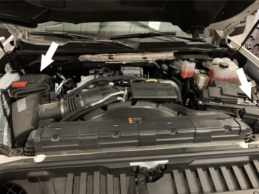
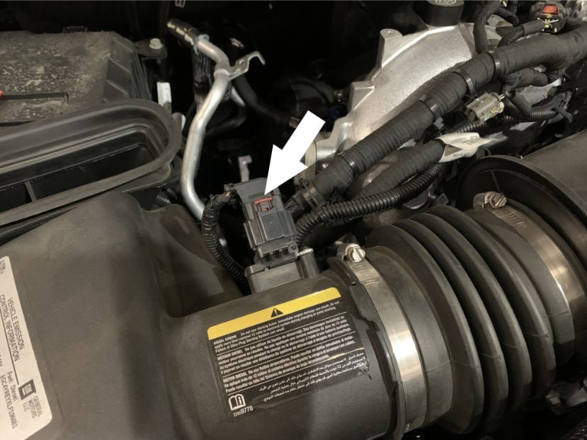
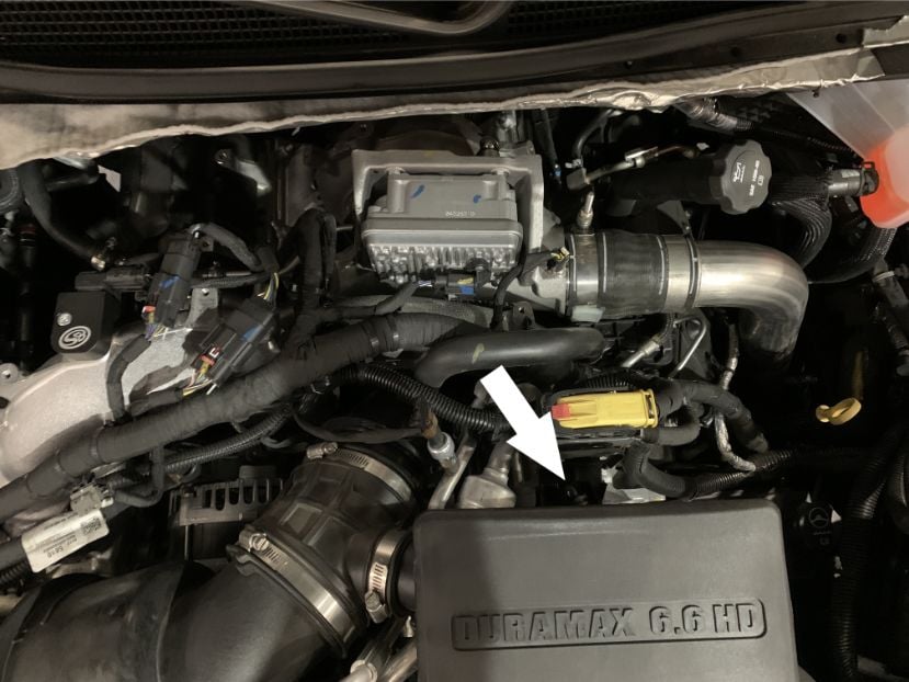
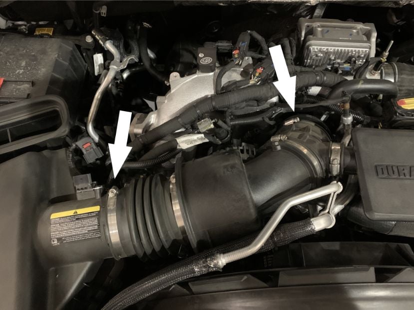
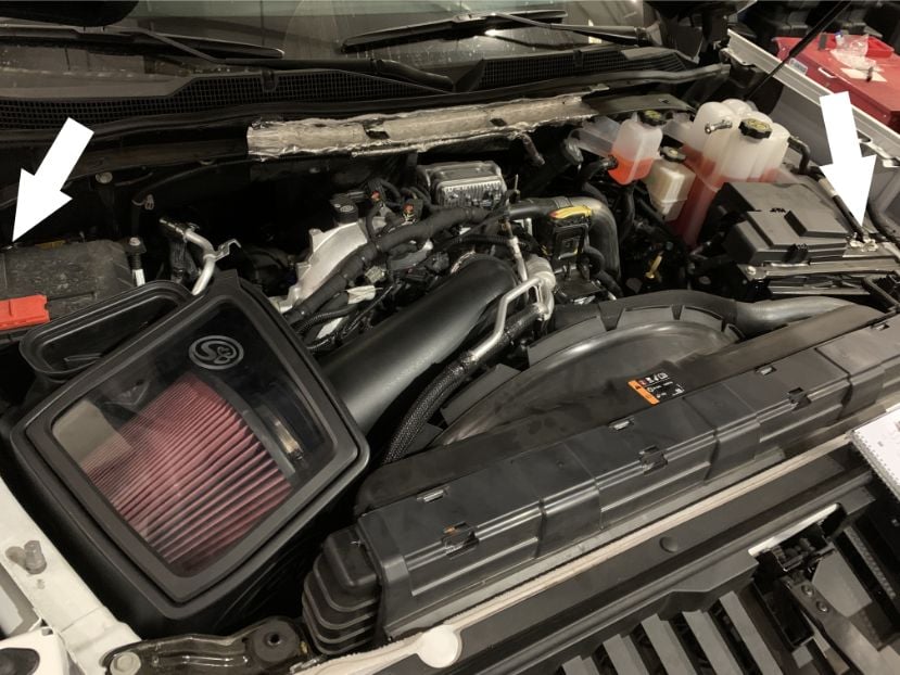
With the ignition switched off and the parking brake set, disconnect the negative battery cables on both the driver and passenger side batteries. The batteries must be disconnected for at least 2 hours to ensure the proper functionality of the kit during use.

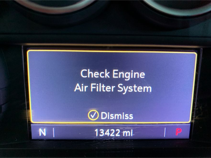
IMPORTANT: Failure to disconnect the battery for a minimum of 2 hours may cause the Check Engine Light to illuminate upon completion of the installation or subsequent operation.

DO NOT SKIP THIS STEP!

Tools Required: Socket Wrench, 8mm Socket

STEP 2

Pull out and push down on the red locking tab to disconnect the MAF sensor harness from the MAF sensor.

STEP 3

Remove the indicated screw securing the intake tube and resonator to the vehicle.

Tools Required: Socket Wrench, 13mm Socket

STEP 4

Loosen the hose clamps connecting the intake tube to the airbox and plastic turbo adapter. Then remove the intake tube from the vehicle.


Tools Required: Socket Wrench, 8mm Socket.

STEP 5

Remove the indicated nut connecting the airbox to the fender of the vehicle. Then lift the airbox out of the vehicle, unseating the prongs on the bottom of the airbox from the grommets which hold it in place. We will be reusing the removed nut in a later step.

Tools Required: Socket Wrench, 10mm Socket.

STEP 6

If the grommets are pulled out of the vehicle with the removal of the airbox, pull them off of the airbox prongs and reinsert them into their holes in the engine bay.

STEP 7

STEP 8

Prepare the S&B CAI for installation by installing the box plug (M), hood scoop seal (C), tube seal (E), and fender seal (B) onto the box. Press the provided grommet (O) into the hole on the fender-facing side of the airbox, and place the shoulder washer (P) into the hole on the grommet securely. You may choose to omit the installation of the box plug for increased airflow.

STEP 9

Install the S&B airbox into the vehicle, verifying that the threaded stem shown travels through the shoulder  washer installed on the last step. Replace the nut removed in step 5 to secure the airbox to the vehicle. 

Note: While placing the CAI into the vehicle, ensure that the front inlet intake tube is out of the way by  gently pushing it to the side so that the S&B air box can move by it.

Tools Required: Socket Wrench, 10mm Socket

STEP 10

Adjust the position of front air inlet so that it is securely inserted and sealed by the front inlet tube seal on the side of the S&B CAI.

STEP 11

Ensure that the #56 hose clamp (G) is loosely attached around the flange of the air filter and place the air filter (D) into the airbox through the top opening. Make sure that the end of the filter opposite of the flange  is pointed toward the rear of the vehicle.

STEP 12

Prepare the S&B intake tube (I) for installation by attaching the provided coupler (F) using the #104 hose clamp (H) provided. Loosely tighten the other #104 hose clamp to the other end of the coupler. 

Tools Required: Socket Wrench, 5/16” Socket.

STEP 13

Remove the MAF sensor from the stock intake air box.

Tools Required: T20 Torx

STEP 14

Attach the MAF sensor to the S&B intake tube using the provided MAF gasket, MAF adapter pad philips head screws. The MAF gasket should be contacting the tube with the adapter, pad followed by the MAF sensor, sitting on top of it.

Tools Required: Phillips Head Screwdriver

STEP 15

Install the S&B intake tube into the vehicle by guiding the large end of the tube through the tube seal found on the air box and into the flange of the air filter. Through this motion, the tube should be oriented so that the end with the coupler attached to it is pointed toward the rear of the vehicle and above the plastic turbo adapter piece. Once you have verified that the intake tube is securely inserted into the filter flange, rotate the intake tube down and away from you, pulling back on the coupler so that it slips around the turbo adapter piece.

STEP 16

Verify that the tube seal completely seals around the complete circumference of the intake tube and then tighten the two #104 hose clamps (H) found around the coupler.

Tools Required: Socket Wrench, 5/16” Socket

STEP 17

Rotate the filter around the end of the intake tube into the position shown so that it does not contact any walls of the airbox and then tighten the #54 hose clamp (G) located around it’s flange.


Tools Required: Socket Wrench, 5/16" Socket

STEP 18

Attach the MAF harness to the MAF sensor by pressing forward on the red locking tab.

STEP 19

Install the lid seal (N) onto the lid (Q) by stretching it around the perimeter of the lid. Snap the lid onto the top of the airbox by pressing down on all of the edges, ensuring that the edge of the lid is securely and completely snapped into place.

STEP 20

After having waited for at least 2 hours, reconnect the battery cables that were disconnected in Step 1.

STEP 21

Inspect your installation, make sure the kit is properly positioned and all fasteners are secured. S&B Filter recommends keeping all stock parts in case you would ever need to reinstall the stock intake. Affix the ID label near the intake kit. Please see the Air Filter Life disable process to complete installation.

STEP 22

To prevent the following message from displaying, the Air Filter Life system will need to be disabled.

STEP 23

Navigate to the Options section of the Driver Information Center, and select the Info Page Options.

STEP 24

Ensure that the Air Filter Life has a green check mark next to it.

STEP 25

Navigate to the Info section of the Driver Information Center, and scroll down to the Air Filter Life section.

Press the wheel in to select the Menu for the Air Filter Life, and select Disable.

STEP 26

The screen should now display “Disabled”, as shown. Please verify the screen still shows disabled after the battery disconnect has been completed. If not, please repeat the process.

Installation of your new Cold Air Intake Kit is now complete.