Install Instructions for 75-5140/75-5140D

Before You Start


VEHILCE FITMENT:  2020-2024 6.7L Powerstroke, Ford, F250/F350/F450

DEVICE NAME: COLD AIR INTAKE  


Please read the entire product guide before proceeding. Ensure all parts are present. If you are missing any of the components, call our customer support at (909) 947-0015. Do not work on your vehicle while the engine is hot. Make sure the engine is turned off and the vehicle is in Park or the Parking Brake is set.

Kit may not fit with the following Aftermarket Parts installed: Body Lift or Lowering Kit, Custom Hood, Throttle Body Spacer / Upgrade.

Required Tools

7mm, 8mm, 10mm, 13mm Socket and Wrench, 10” Socket Extension or 4” 6” Socket Extensions, 13mm Open/Box Combination Wrench, 5/16” Nut Driver, T20 Torx Bit/Driver, Torque Wrench, 1/4" Drive, Panel Popper, Phillips Screwdriver, Wire Cutters.

Note: Approximate Install Time: 1 Hr 00 Mins for Kit Installation, 2 Hr 00 Mins for Battery Disconnect

STEP 1

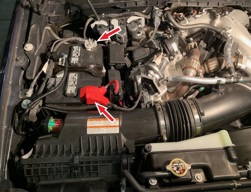
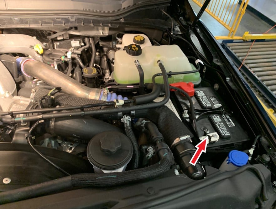
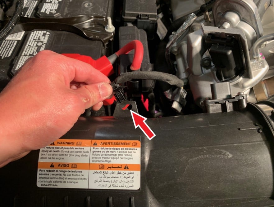
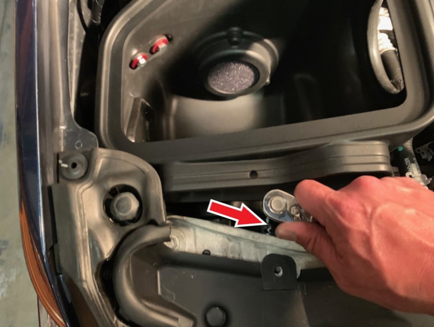
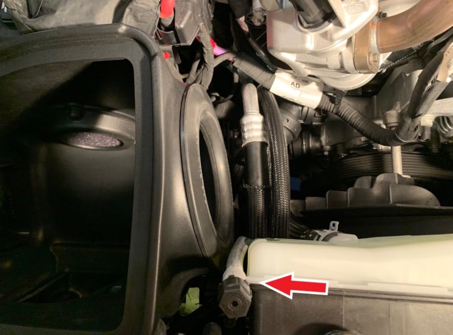
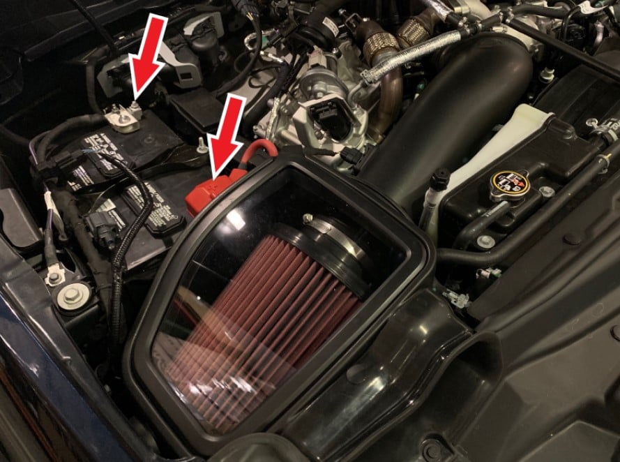
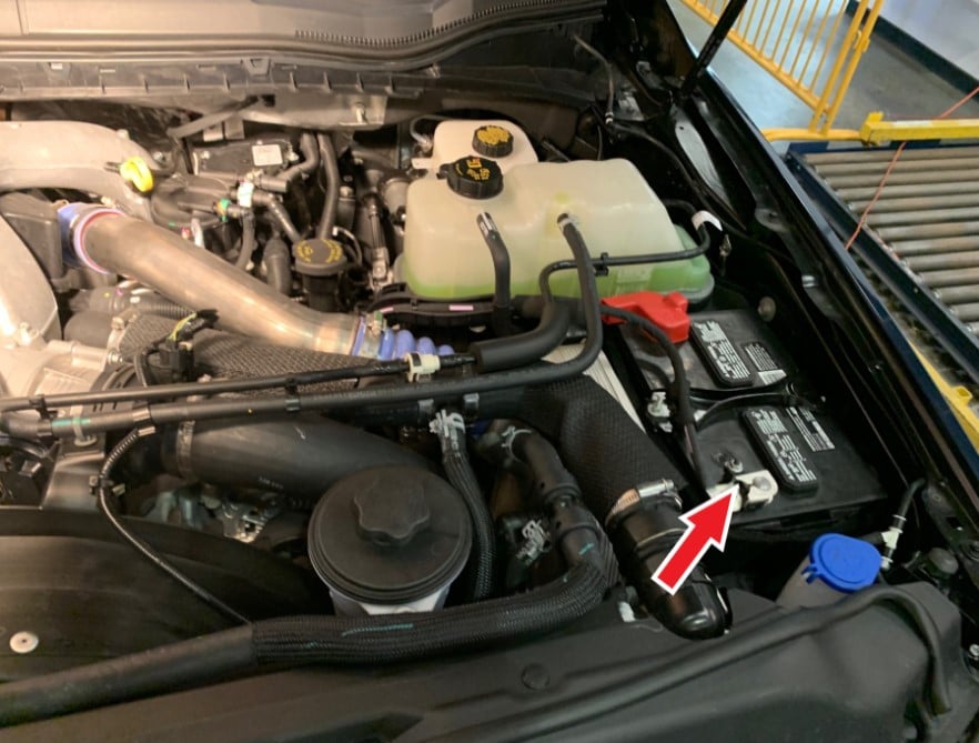
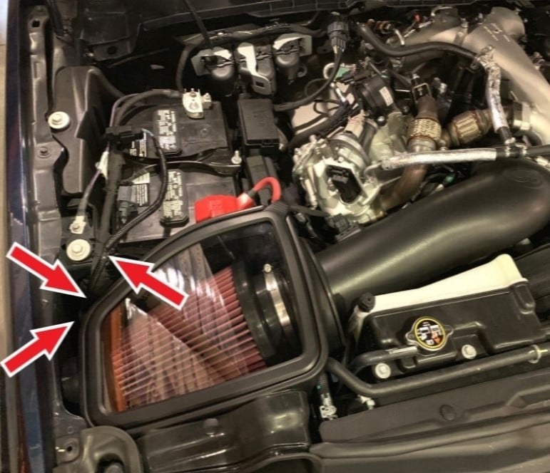
With the ignition switched off and the parking brake set, disconnect the negative battery cables on both batteries and the positive battery cable on the passenger side.

Note: Failure to disconnect the battery for 2 hours may cause the CEL to illuminate upon completion of the installation and subsequent operation. DO NOT SKIP THIS STEP!

Tools Required: 10mm Socket/Wrench

STEP 1B

STEP 2

Disengage the white locking clip, press down on the tab, then pull out to disconnect the MAF sensor harness from the MAF sensor.

STEP 3

Remove the ribbed push in clip on the wiring harness from the stock intake lid.

Tools Required: Panel Popper or Flat Blade Screwdriver

STEP 4

Loosen the hose clamps on the intake tube connected to the turbo inlet and intake box.

Tools Required: 7mm Socket/Wrench or Flat Blade Screwdriver

STEP 5

Remove the coolant line from the intake tube clip then remove the intake tube from the vehicle.

STEP 6

Unhook the three clips on the stock intake box lid. Remove the stock intake box lid from the vehicle.

STEP 7

Carefully remove the stock intake filter.

STEP 8

Pop-out the stem and remove the push in rivet securing the stock front inlet. Set the push in rivet aside, it will be reused in Step 37.

Tools Required: Panel Popper or Flat Blade Screwdriver.

STEP 9

Wiggle the stock front inlet loose and lift up to remove it from the vehicle.

STEP 10

Using socket extension(s), remove the screw holding the stock intake box to the grill inlet duct. Set the screw aside to be reused in Step 27.

Tools Required: 10” Socket Extension or 4” + 6” Socket Extension, 8mm Socket/Wrench

STEP 11

Firmly but carefully rock and lift the intake box free from the lower grommet and free the side rubber bushings from the side saddle bracket. Remove the intake box from the vehicle.

STEP 12

Make sure the bottom box grommet stayed in the vehicle and did not get pulled out with the intake box.

STEP 13

Remove the two screws that hold the saddle bracket and remove the bracket from the vehicle. Set the screws aside, they will be reused in Step 21 and Step 25.

Tools Required: 13mm Socket/Wrench

STEP 14

Install Front Scoop Bracket (B) to the Air Box (A) using Hex Flange Bolt (C). Slide the Front Scoop Bracket (B) towards the scoop opening and tighten Hex Flange Bolt (C).

STEP 15

Install Washer (D) to the bottom of Air Box (A) using Hex Flange Bolt (C).

Tools Required: 10mm Socket/Wrench or Box/Open Wrench

STEP 16

Install Foam Filter (J) and Foam Retainer (K) to the Air Box (A) using M4 Screws (L).

STEP 17

Install Grommets (E) to the Air Box (A). Make sure that Air Box (A) is fully seated into the groove of both Grommets (E) and that both sides of the Grommets (E) are flat against the wall of the Air Box (A).

STEP 17B

STEP 18

From the inside of the Air Box (A), install Shoulder Bushings (F) into the Grommets (E)


STEP 19

Install Box Seal (M) to the Air Box (A). Make sure that the Air Box (A) is fully seated into the groove of Box Seal (M).


STEP 20

Determine if you want to install the Air Box Plug (N) to the Air Box (A). See the “Air Box Plug Testing” section at the beginning of the Install Instructions to decide the desired setup. If the Air Box Plug is desired, simply press the Box Plug into the Box opening until it snaps fully into place.


STEP 21

Install the Air Box Bracket (H) onto the fender frame using the threaded hole (closest to the battery) of the saddle bracket removed in Step 13. Reuse one saddle bracket screw removed in Step 13 and hand tighten only.

Tools Required: 13mm Box/Open 

STEP 22

Carefully work the Air Box (A) into the vehicle. The space is tight but carefully move/rotate the box to make space for the grill inlet duct, fender, and coolant reservoir as you lower the Air Box. Once the Air Box is below the fender it will become easy to position the Air Box properly then push down to fully seat the Washer (D) into the stock bottom box grommet shown in Step 12. The AirBox should snap into the grommet.


STEP 23

Position the Air Box so that the hole in Air Box (A) is in line and matched with the threaded hole in the fender frame and the holes in the Shoulder Bushings (F) are also in line and matched with the threaded holes in Air Box Bracket (H). Rotate the Air Box Bracket (H) as required.

STEP 24

After the holes in Step 23 are in line and matched, make sure that the Front Scoop Bracket (B) slotted hole is over the threaded hole of the stock grill inlet duct. If the Front Scoop Bracket (B) needs to be repositioned, remove the Air Box (A) from the vehicle and readjust the Front Scoop Bracket (B).

STEP 25

After the holes in both Step 23 and Step 24 are aligned, reuse the OE saddle bracket screw removed in Step 13 to fasten the Air Box (A) to the fender frame. Use the M8 Screws (G) to fasten the Shoulder Bushings (F) to the Air Box Bracket (H). Tighten all fasteners.

Tools Required: 13mm Socket/Wrench

STEP 26

Tighten the screw that was hand tightened in Step 21 to secure the Air Box Bracket (H) to the fender frame.

Tools Required: 13mm Box/Open Wrench

STEP 27

Reuse the screw removed in Step 10 to fasten the stock grill inlet duct to the Front Scoop Bracket (B). Use tape to hold the screw to the socket if you have trouble guiding the screw into the stock grill inlet. Be careful not to over tighten since the threaded hole in the grill inlet duct is plastic.

STEP 28

Carefully bend the AC service port line slightly so that the center of the cap lines up with the seam of the coolant reservoir to give clearance for the Intake Tube (T).

STEP 29

Remove the two screws holding the stock MAF sensor to the stock intake box lid and remove the stock MAF sensor.

Tools Required: T20 Torx Bit/Driver

STEP 30

Make sure the stock gasket is on the MAF sensor and place the MAF Mount (V) first and then the MAF Mount Gasket (U) second on to the stock MAF sensor as shown.

STEP 30B

STEP 31

Mount the MAF sensor assembly to the Intake Tube (T) using two #8-32 Screws (W). Make sure that the arrow on the MAF sensor is pointing towards the oval end of the Tube (T).

Tools Required: Phillips Screwdriver

STEP 32

Slide the Coupler (Y) over the Intake Tube (T) with the two #72 Hose Clamps (AA) up to the edge of the oval end of the Intake Tube as shown. Leave the Hose Clamps loose.

Tools Required: 5/16” Nut Driver

STEP 33

Insert the Intake Tube (T) into the Box Seal (M) located on the Air Box (A). Work the Intake Tube (T) slowly, at the angle shown, until the bead on the Tube is up against the Box Seal (M).


STEP 34

Rotate the Intake Tube (T) until it is aligned with the turbo inlet and then slide the Coupler (Y) over the turbo inlet. Fully seat the Coupler (Y) until it is up against the flange of the turbo inlet all around. The bead on the Intake Tube (T) should also be by the edge of the Coupler (Y) all around.


STEP 35

The coolant hoses will be sitting on top of the Coupler (Y) so position the Hose Clamp screws away from the hoses as shown, then tighten both #72 Hose Clamps (AA).

Tools Required: 5/16” Nut Driver.

STEP 36

Attach the Air Box Inlet (P) onto the Air Box (A) with the Plastic Rivets (R). Squeeze the Plastic Rivets (R) together so they lock into place.


STEP 37

Secure the Air Box Inlet (P) onto the vehicle with the push in rivet removed in Step 8. Make sure the push in rivet is fully inserted and the center stem pushed all the way down.

STEP 38

Insert the Filter (AB) with #80 Hose Clamp (AC) into the Air Box (A) with the Filter flange pointing up.

STEP 39

Install the Filter (AB) and #80 Hose Clamp (AC) onto the Intake Tube (T). Insert the Intake Tube (T) fully into the Filter (AB) until it stops on the Filter flange shoulder.  The base of the Filter flange should line up with the bead on the Tube. Rotate the Filter until the straight section of the filter becomes vertical as shown. Tighten the Hose Clamp (AC).

Tools Required: 5/16” Nut Driver.

STEP 39B

STEP 40

Peel off the protective covering on the clear Lid (AE). Don’t forget to remove the protective covering around the S&B logo.

STEP 41

Install the Lid Seal (AD) around the outside edge of the clear Lid (AE).

STEP 42

Install the clear Lid (AE) with Lid Seal (AD) onto the Air Box (A). Start by inserting the Lid Seal groove over the Air Box opening on one corner first and then work your way around the Air Box. Make sure that the Lid Seal groove snaps over the entire Air Box opening. Check all around the Lid Seal snap groove to make sure it has snapped over the entire Air Box opening.


STEP 43

Reconnect the MAF sensor harness to the MAF sensor. Make sure to engage the white locking clip. Then insert the ribbed push in harness clip into the slotted hole located in Air Box (A).


STEP 44

After the batteries have been disconnected for at least 2 hours, reconnect the positive battery terminal on the passenger side first and torque the terminal clamp nut to factory specifications, 80 lb-in (9 Nm), and place the cover over the terminal. Then reconnect the negative terminals on both batteries and torque the terminal clamp nut to factory specifications, 80 lb-in (9 Nm).

Tools Required: 10mm Socket/Torque Wrench

STEP 44B

STEP 45

Look for any loose wires/harness that may be close or touching the Intake Box (A) or Air Box Bracket (H) and secure them away with Cable Ties (AF) to prevent them from wearing during vehicle movement and vibration.


STEP 46

Inspect your installation, make sure the kit is properly positioned and all fasteners and hose clamps are secured. Keep all stock parts in case you would ever need to reinstall the stock intake assembly. Affix the ID label near the Intake kit. If you are an installer, give the owner the QR code for the Installation Instructions so that he/she is aware of the Maintenance and Operation procedures given at the beginning of the Instructions. The installation is now complete.


CARB EO LABEL

Please affix the included CARB-approved EO label in an area under the hood. We recommend placing it on the radiator shroud, or the underside of the vehicle's hood near the S&B product.