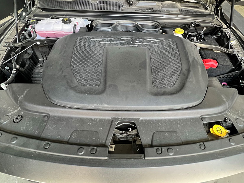
Step 1
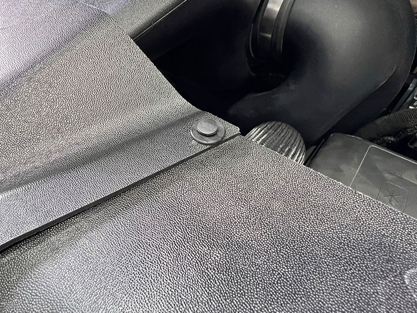
With the engine off and cooled down open the hood to begin the installation by pulling the engine cover firmly away from the stock air cleaner system.
VEHILCE FITMENT: 2021-2024 6.2L V8, Ram, 1500 TRX
DEVICE NAME: COLD AIR INTAKE
Please read the entire product guide before proceeding
With the engine off and cooled down open the hood to begin the installation by pulling the engine cover firmly away from the stock air cleaner system.
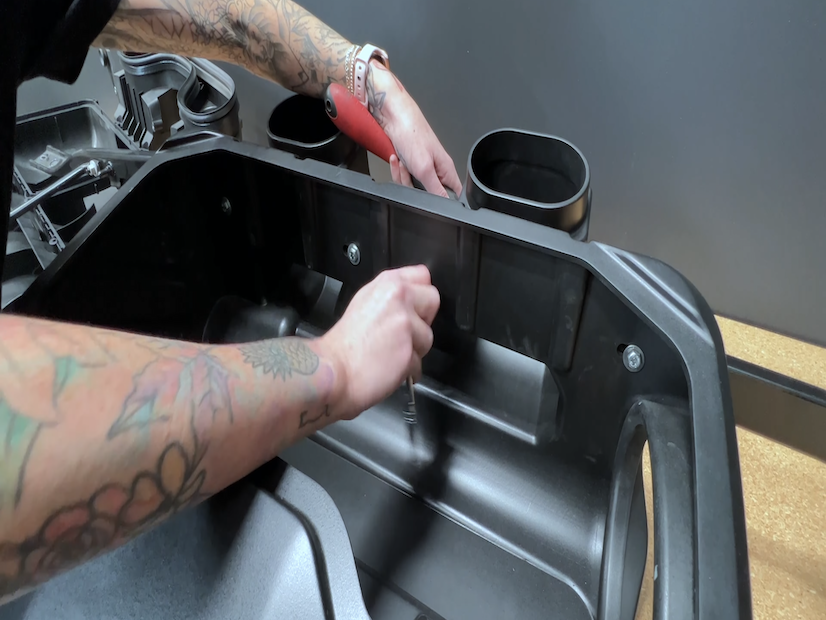
Remove the 14 reusable plastic rivets securing the radiator cover using a flathead screwdriver or panel popper. Remove the radiator cover from the engine and set it to the side. Set the rivets to the side to be used later.

Using a T27 Torx bit or 10mm socket, unthread the 2 front screws securing the front of the airbox. Set the screws to the side to be reused later in the installation.

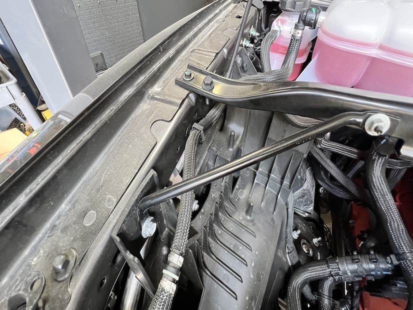
Begin removing the airbox support bracket by using a 10mm and 13mm socket at the six locations at both passenger and driver's fender sides. Collect those 6 bolts to be reused later.

Undo the hose clamp at the stock airbox to the intake tube connection using a 5/16” driver or flat head screwdriver.
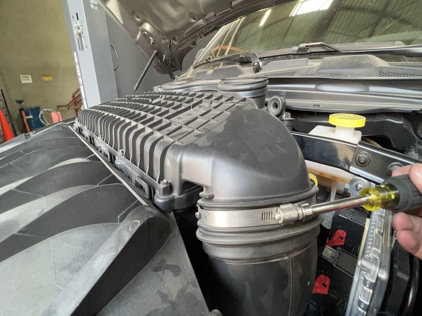
Pry up the stock airbox away from the tube and pull the airbox and support bracket assembly out of the vehicle. Set the assembly to the side.

At the tube, unplug the IAT sensor harness from the stock sensor connection.
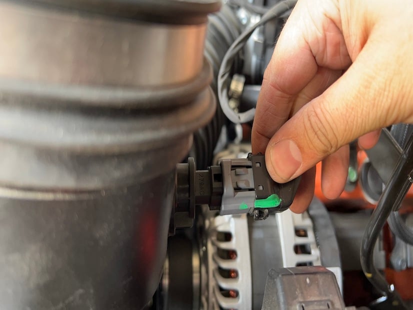
Using a knife or cutting tool, score the nylon shrink-wrapped hose at the solenoid connection. Be careful to only cut deep enough to be able to split the hose and to not cut into the plastic breather underneath. Once cut, pry the hose away from the breather.

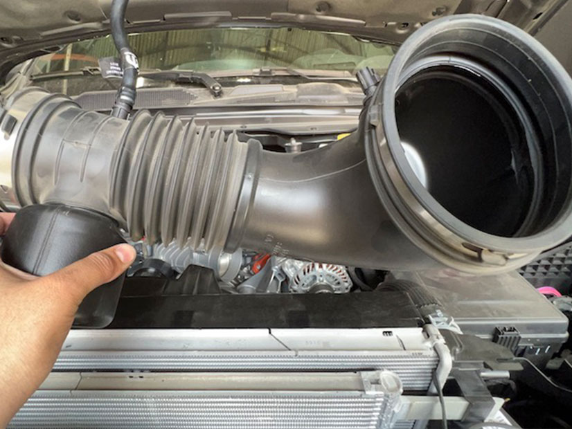
Loosen the hose clamp at the throttle body and disconnect the intake tube. Pull the tube assembly out of the engine compartment and set it aside.
Remove the hardware securing the airbox to gain access to the bracket mounting hardware using a long reach flathead or Phillips head screwdriver. 10 locations in total.

Remove the 4 airbox bracket mounting screws using a T27 Torx bit and driver. Separate the stock airbox from the mounting bracket support. Set the support bracket to the side to be reused.

Using a flathead screwdriver pry off the grommets and shoulder spacers from the front-most area of the stock airbox.

Transfer the shoulder spacers and grommets to the S&B mounting brackets in the orientation as shown with the flat of the shoulder bushing away from the screw and washer mounting area.

Install the S&B IAT Sensor grommet onto the S&B intake tube. Transfer the IAT sensor from the OEM tube into the S&B tube as shown. The locking tab should rotate over the ramp and lock into position, use the turn arrow for indication.

Install the CCV vent silicone-wrapped hose onto the S&B tube at the breather connection using 2 #12 hose clamps.

Install the coupler and hose clamps onto the S&B Tube.

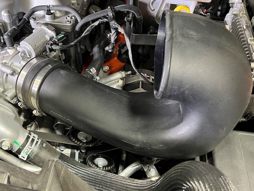
Install the tube into the vehicle by pushing the coupler over the throttle body. Push the CCV tube over the CCV connection end, and rotate into position as needed. Be aware to allow the fuse box clearance to be removed easily for future access. Tighten the hose clamps.
Reconnect the IAT wire harness to the IAT Sensor on the S&B Tube.

Attach the 2 airbox mounting brackets onto the front of the S&B Airbox using the supplied 1/4 -20 Torx flat head screws and a T27 Torx Bit.

The right (passenger) side bracket has an additional bend.

Install the silicone one-way valve onto the bottom of the airbox
Attach the stock airbox support bracket to the back of the S&B Airbox using the provided M6 washers nuts and screws, and a 10mm socket and wrench or 2 10mm sockets. Run the screws through the S&B airbox lining up with the holes in the bracket. Do not tighten completely.
Install the silicone hood scoop seals onto the airbox.

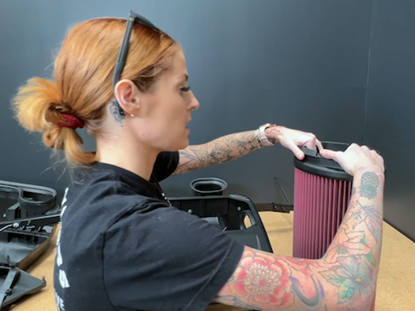
Install the S&B snap-in filter into the airbox. For easier installation, fold the filter flange inward towards the inside of the filter. Once the filter is in the airbox push the snap in a portion of the flange through the opening of the airbox. After the filter is snapped into place, fold the flange to its original position.
Install the hose clamp over the filter flange loosely.

Install the airbox, support bracket, and filter assembly into the engine compartment. Push the intake tube into the filter flange and verify the S&B front airbox support brackets and the stock airbox support bracket align with their mounting holes.
Tighten the air filter onto the S&B intake tube with the hose clamp from Step 24.

Reinstall the airbox support bracket hardware in their positions from Step 4 using 10mm and 13mm sockets.
Install the front S&B airbox bracket hardware using a T27 Torx bit and driver or 10mm socket. After all support brackets are secured, tighten the 4 M6 screws and nuts from Step 21.

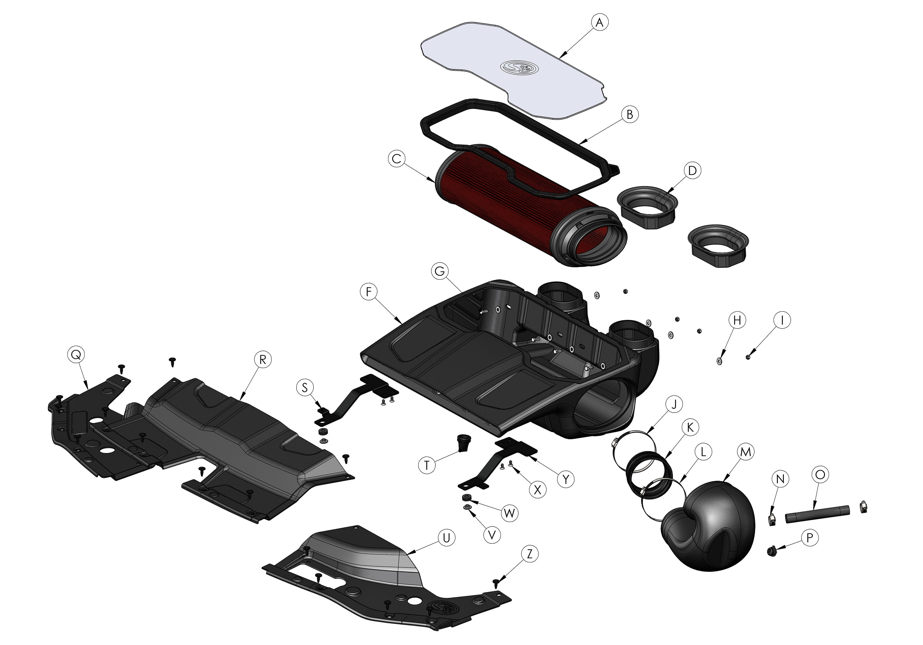
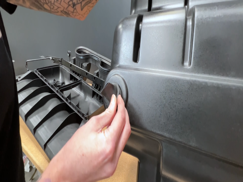
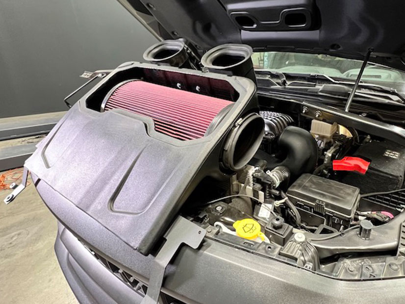
Remove the protective wrapping of the polycarbonate lid. Install the snap-in silicone lid seal around the polycarbonate lid. Install the snap-in lid assembly onto the airbox. Slide into the box as shown and use pressure around the perimeter to install the Snap-in lid.

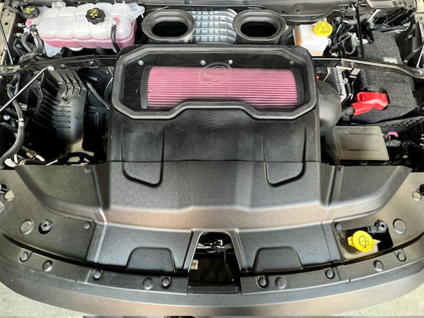
Place the driver's side and passenger's radiator closeout into position over the intake and engine. Place the front cover over those two closeouts. Install the included plastic reusable rivets into the S&B radiator cover hole positions.

Use the stock rivets at the two highest points on the cover.

Use the S&B supplied rivets at the 2 locations nearest to the S&B airbox.
Inspect your installation. Make sure the kit is properly positioned and all fasteners and hose clamps are secured. Keep all stock parts in the event you would ever need to reinstall the stock intake assembly. If you are an installer, give the owner the QR code for the Installation Instructions so that he/she is aware of the Maintenance and Operation procedures are given at the beginning of the Instructions. The installation is now complete.
Please affix the included CARB-approved EO label in an area under the hood. We recommend placing it on the radiator shroud, or the underside of the vehicle's hood near the S&B product.
