STEP 1
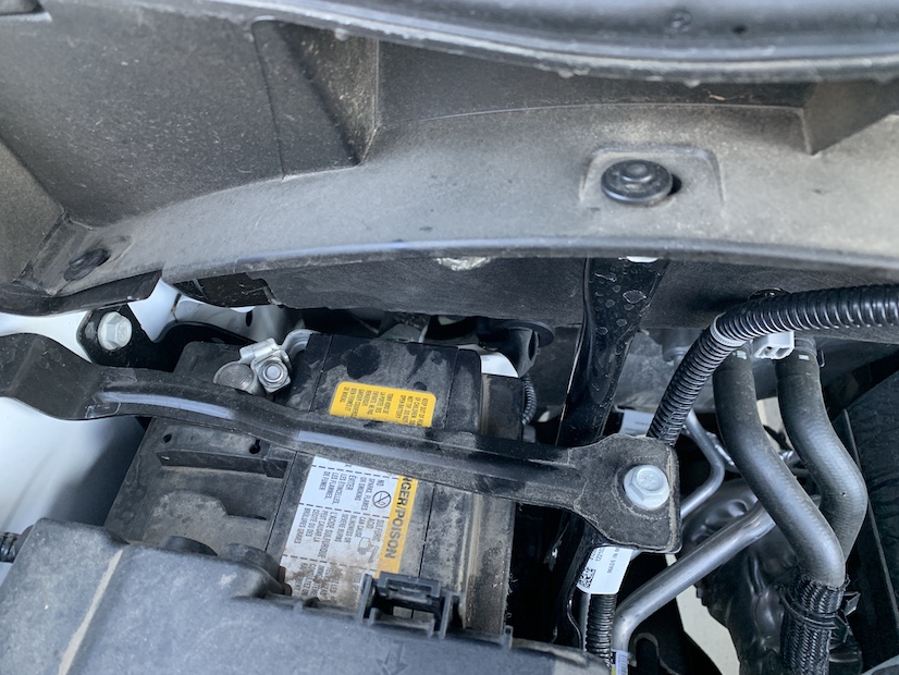
Disconnect negative terminal on Battery
IMPORTANT: Failure to disconnect the battery for a minimum of 2 hours may cause the Check Engine Light to illuminate upon completion of the installation or subsequent operation.
DO NOT SKIP THIS STEP!
STOP! IMPORTANT INFORMATION
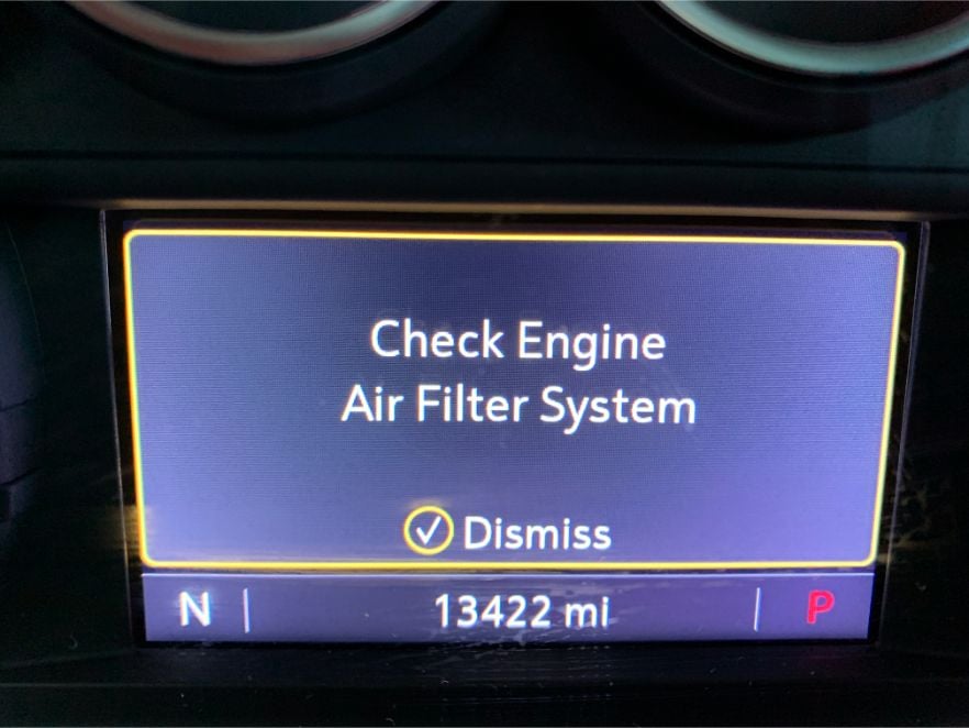
Warning: Failure to disable the Air Filter Life System will cause a warning light that can only be reset by a GM Dealer. Please ensure you have disabled the system prior to driving the vehicle with your new S&B Intake. Please refer to steps 38-42 to cover this procedure.
Disconnect negative terminal on Battery
IMPORTANT: Failure to disconnect the battery for a minimum of 2 hours may cause the Check Engine Light to illuminate upon completion of the installation or subsequent operation.
DO NOT SKIP THIS STEP!
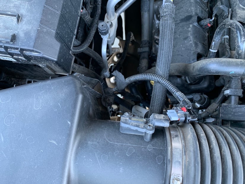
Disconnect Mass Airflow Sensor Harness - Slide red locking tab away from MAF sensor to release.
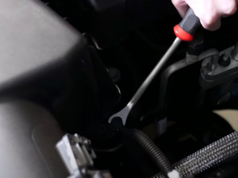
Remove Hood Latch Handle - 2 Torx screws.
Tool Needed: t15 torx bit
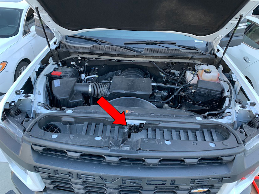
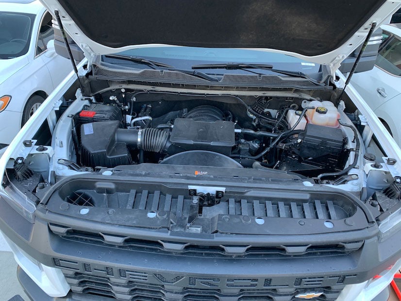
Remove Radiator Cover - Use a panel popper to remove all of the push rivets.
Panel Popper
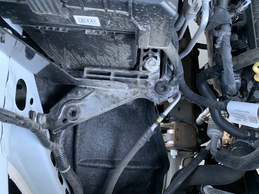
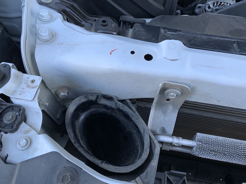
Use a panel popper to remove the push rivet securing the intake duct to the core support
Tool Needed: Panel removal popper.
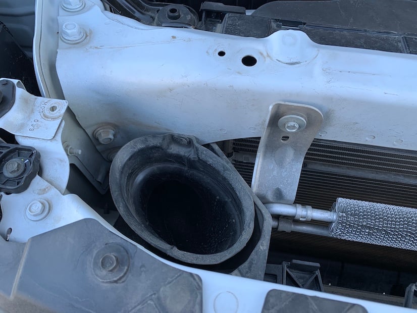
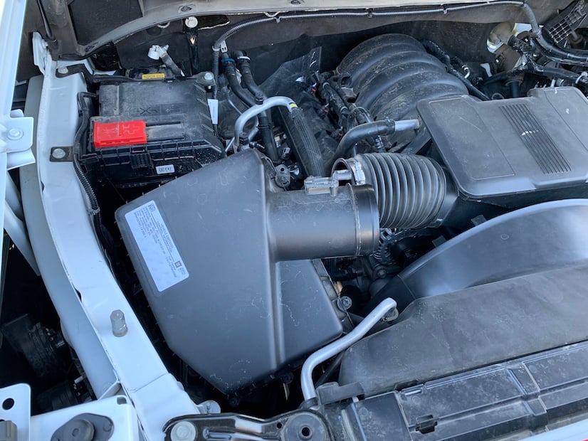
Pull up on the intake duct until it separates from the stock airbox.
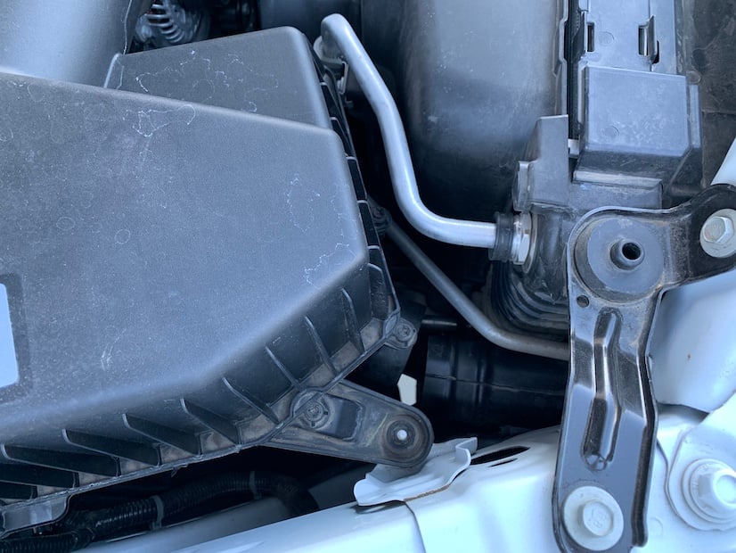
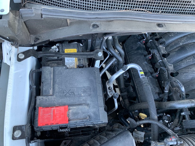
Remove the 10mm nut that secures the airbox.

Loosen the hose clamp that secures the intake box to the factory resonator.
Tool Needed: Flathead screwdriver.
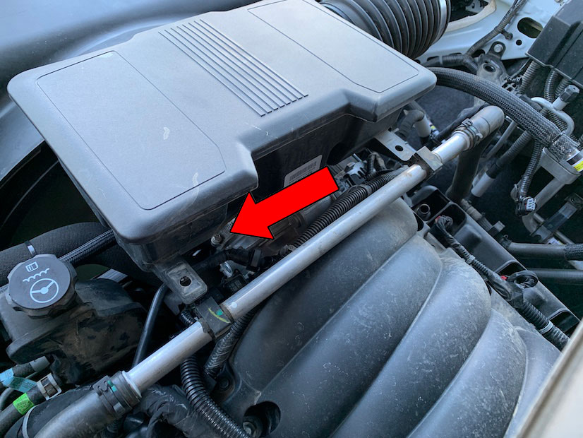
Use a panel popper tool to remove the MAF harness from the airbox.
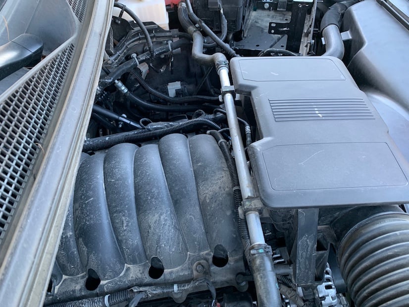
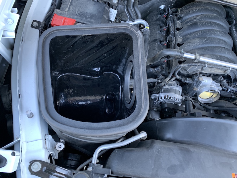
Remove the airbox from the vehicle.
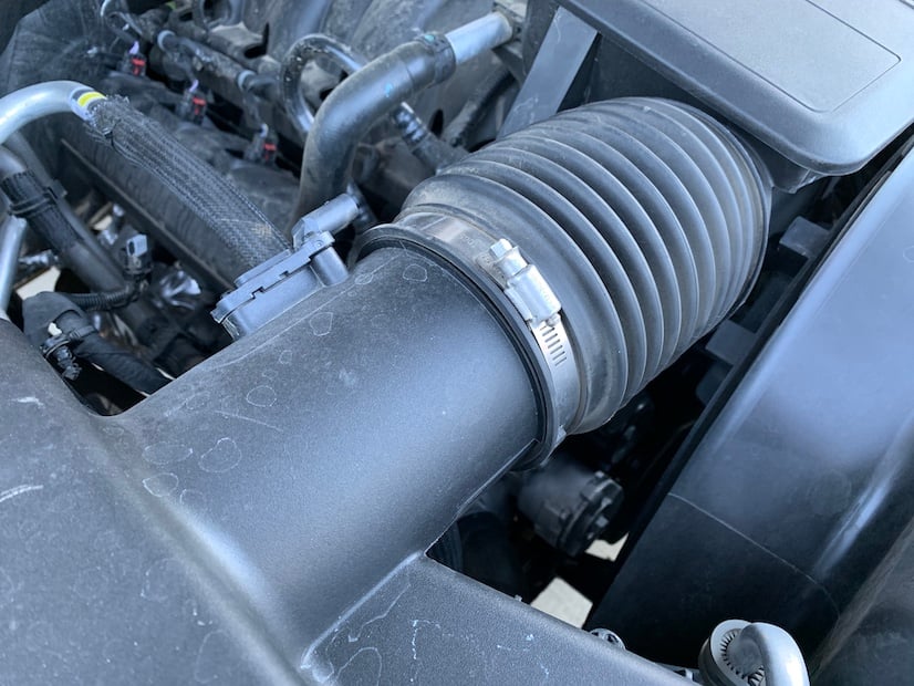
Pull upwards on the coolant line to remove it from the resonator.
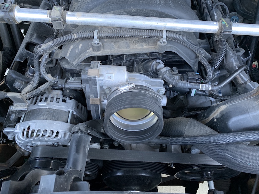
Loosen the hose clamp at the throttle body.
Note:Flathead screwdriver of 5/16 nutdriver.
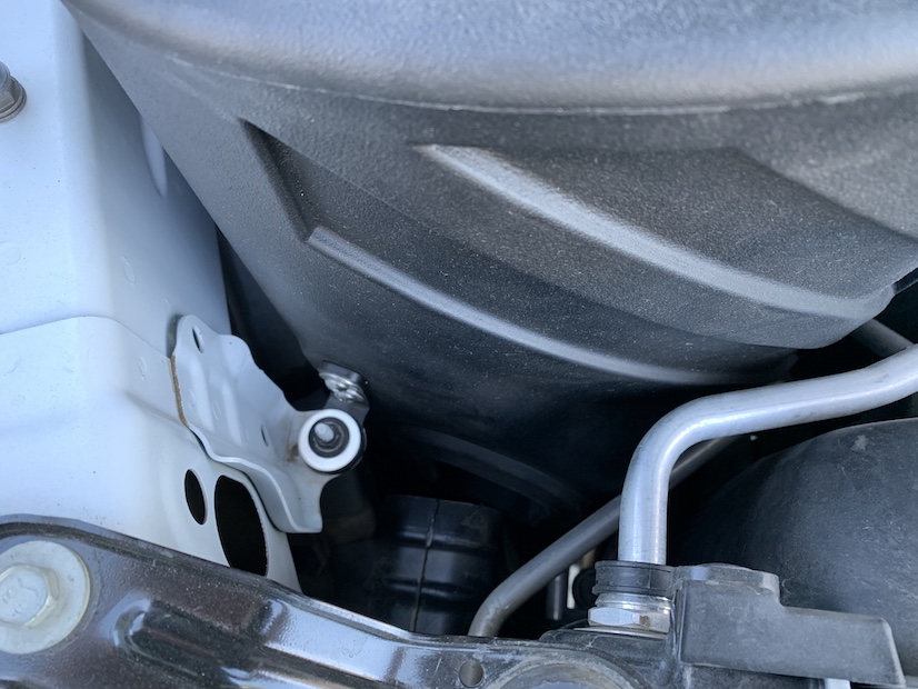
Push down on the gray tab to disconnect the Crank Case Vent line from the resonator.
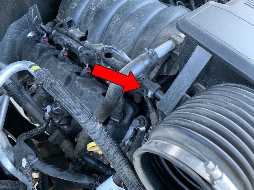
Remove the tube and resonator assembly from the vehicle. Rotate the assembly 90 degrees and pull towards the passenger side of the vehicle to free it from the mounting bracket.

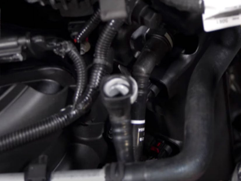
Remove the Crank Case Vent tube from the vehicle. Push down on the gray tab and pull away from the intake.
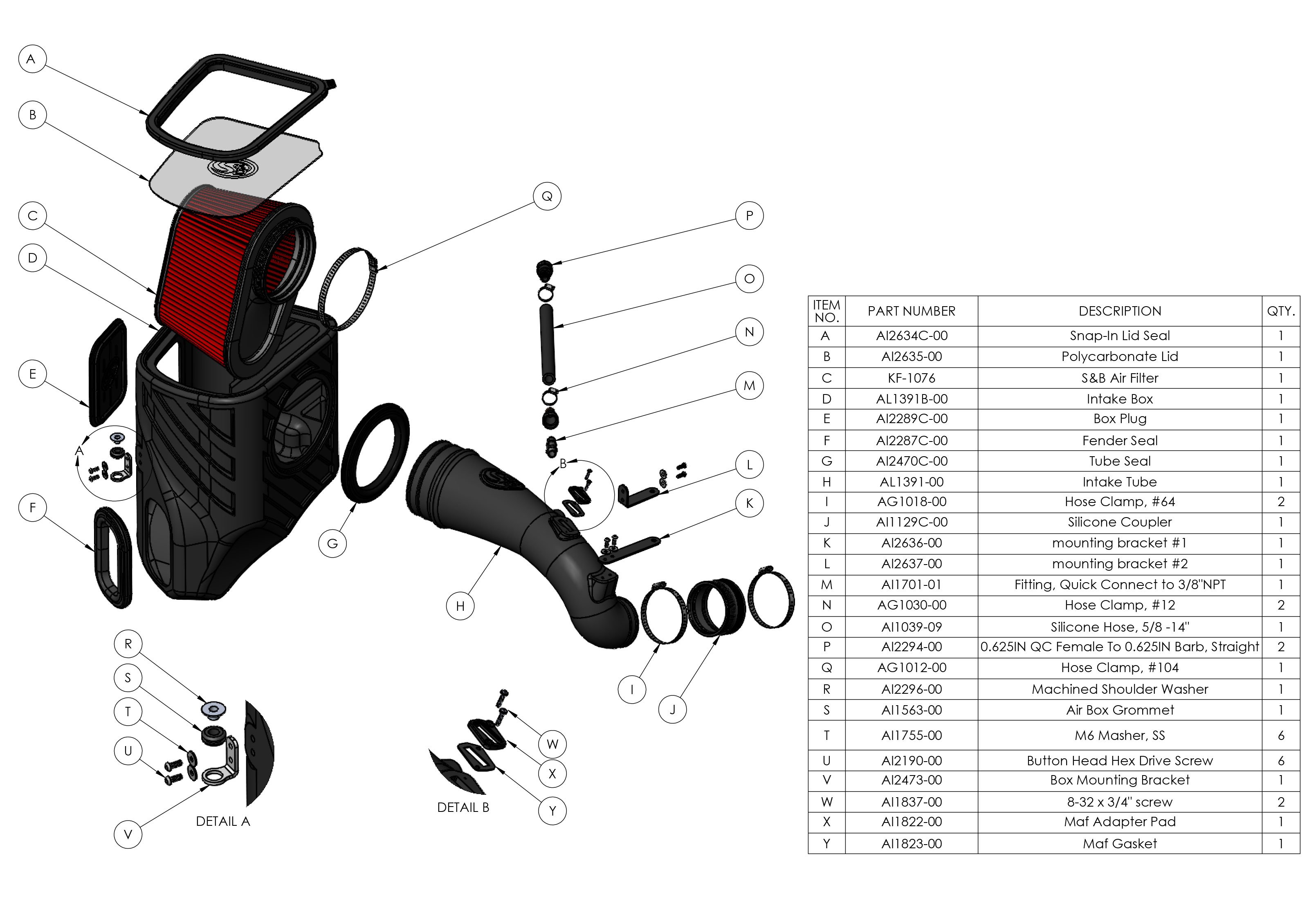
Install the silicone scoop seal and airbox mounting bracket onto the airbox. Use the provided grommet and shoulder washer.
Install the tube seal into the airbox.

(Optional) Install the box plug into the airbox. (We recommend installing the box plug in warmer climates to ensure your vehicle gets the coldest air possible.
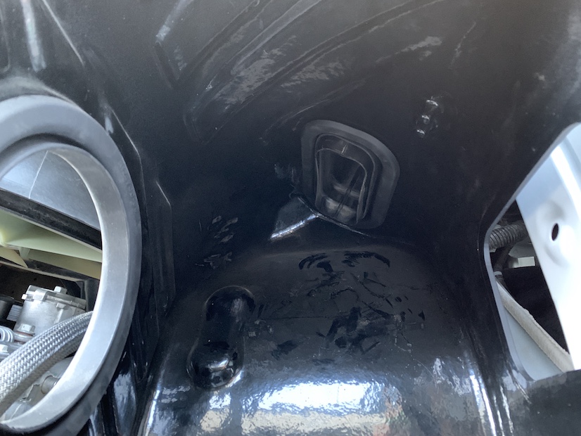
Ensure the airbox mounting grommets are in place prior to installing the S&B box. You may need to remove them from the original airbox.
Install the S&B air box into the vehicle. Line the mounting prongs up with the grommets and slide the mounting tab over the stud on the front side of the airbox.
Use a 10mm ratchet to reinstall the nut on the mounting bracket.
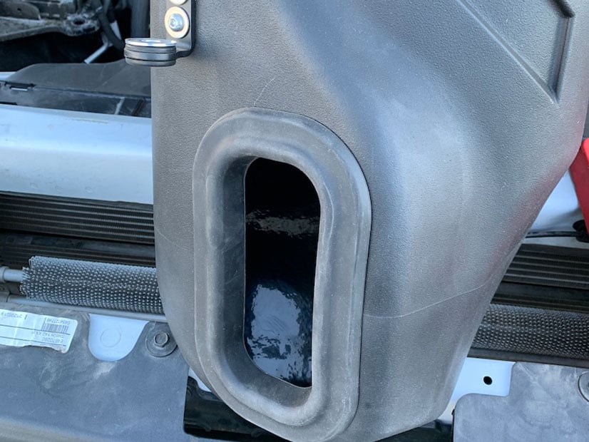
Install the factory air inlet scoop into the S&B box.
Reinstall the plastic rivet into the factory air scoop.
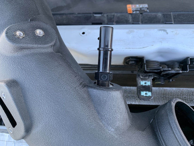
Install the CCV quick connect fitting into the tube. Tighten by hand until it is snug and complete one revolution with a wrench. Do not over tighten or this fitting will crack.
Transfer the mass airflow sensor onto the tube. Install the foam MAF gasket between the plastic spacer and the tube itself. Then, use the provided longer phillips screws & washers to reinstall the sensor. Tighten until the foam gasket is compressed to ensure a good seal.
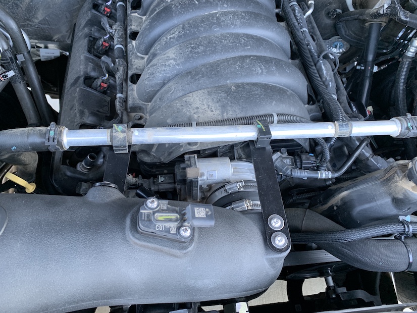
Install the coolant line mounting brackets onto the tube using the 4 allen screws included. The coolant line removed from the resonator will snap into these brackets.

Install the silicone coupler and clamps onto the throttle body. Tighten the throttle body side clamp using a flathead screwdriver or 5/16” nut driver.
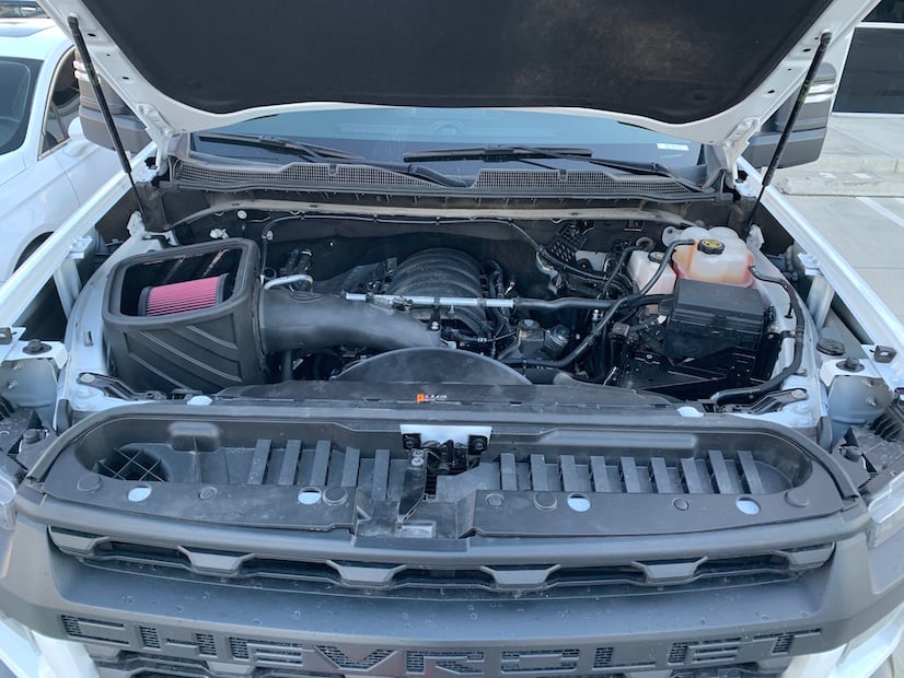
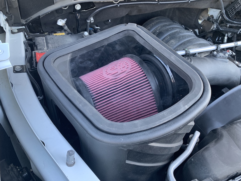
Install the air filter into the airbox.
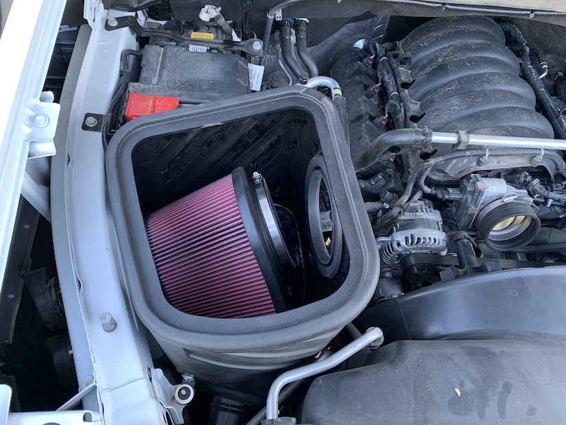
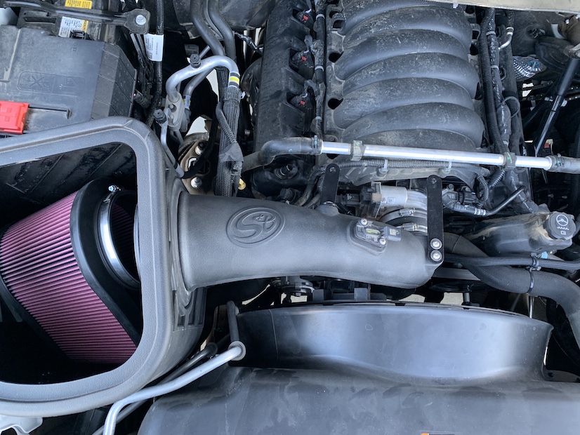
Place the air filter into the airbox, then install the tube into the airbox and coupler on the throttle body. Tighten the hose clamps on the tube and filter using a flathead screwdriver or 5/16” nut driver.
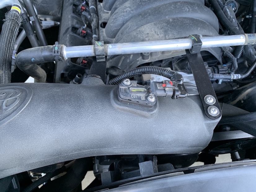
Snap the coolant line into the the mounting brackets. You may need to pop the driver side clip open with a flathead screwdriver in order to slide it over into the proper position to attach to the mounting bracket. Then snap it closed once it is lined up.
Reconnect the mass airflow sensor.
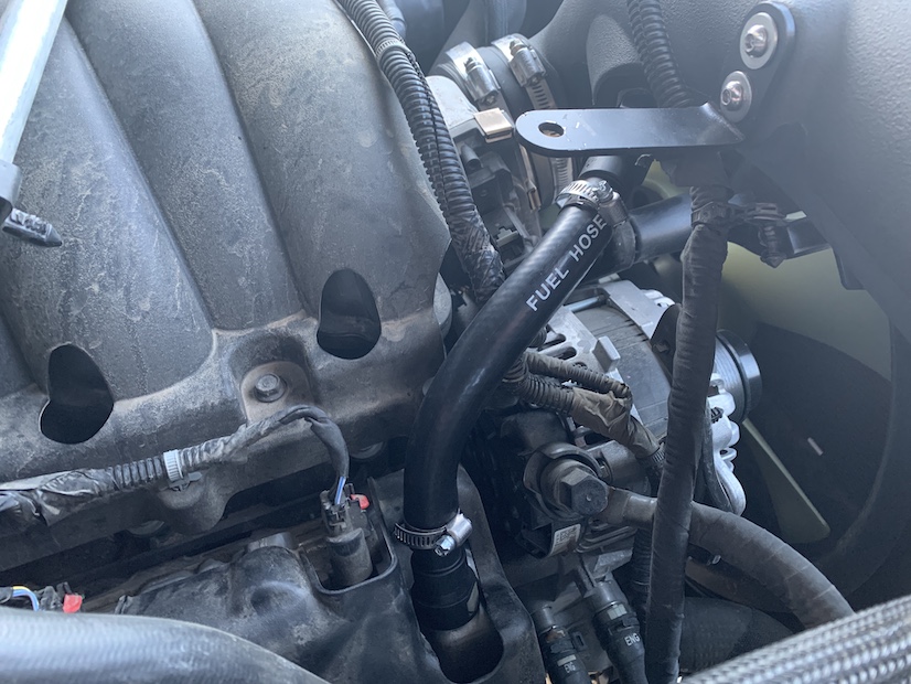
Install the quick connect fittings into the hose and secure with the provided hose clamps. Then, install the hose assembly into the vehicle. You will need to measure and cut the hose to length. Be sure you hear an audible click with both fittings to ensure they are secure.
Reinstall the radiator cover using the original push rivets. Reinstall the hood latch handle with the screws removed earlier.
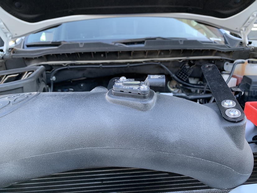
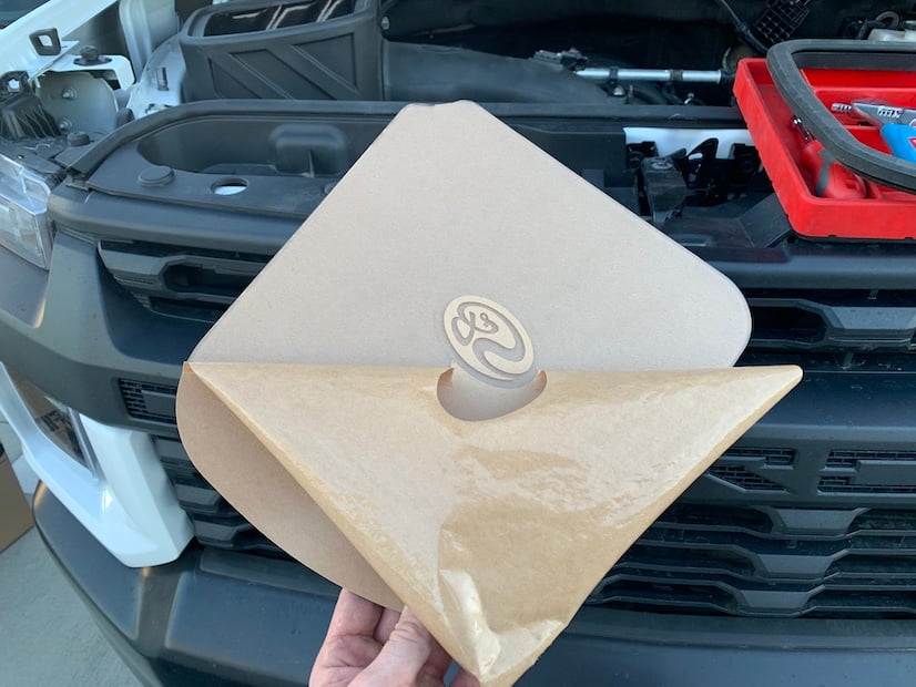
Remove the paper backing from the lid. Be sure to also remove the paper inside the S&B logo.
Install the Snap-In Lid Seal onto the Lid.
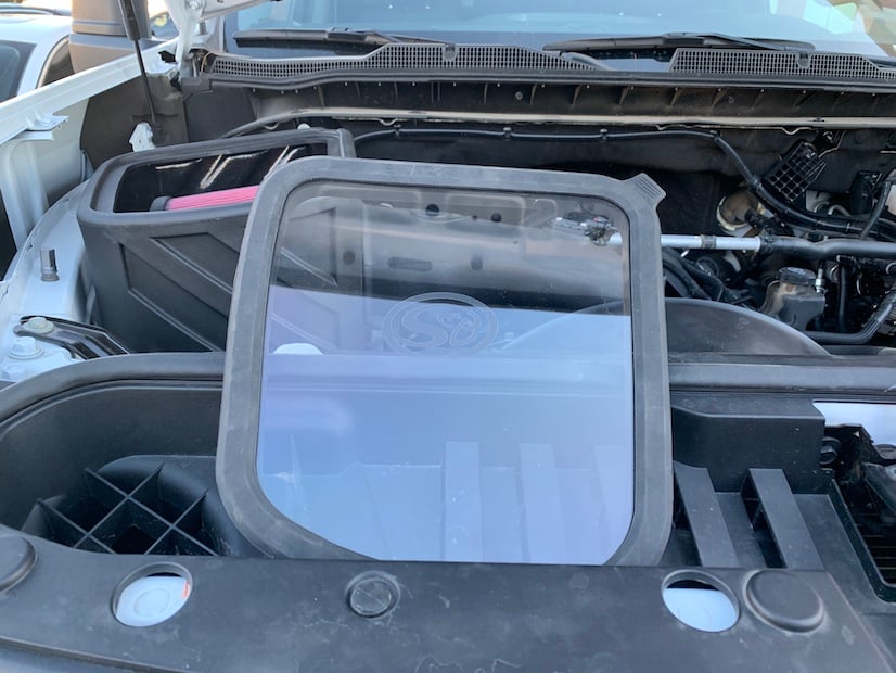
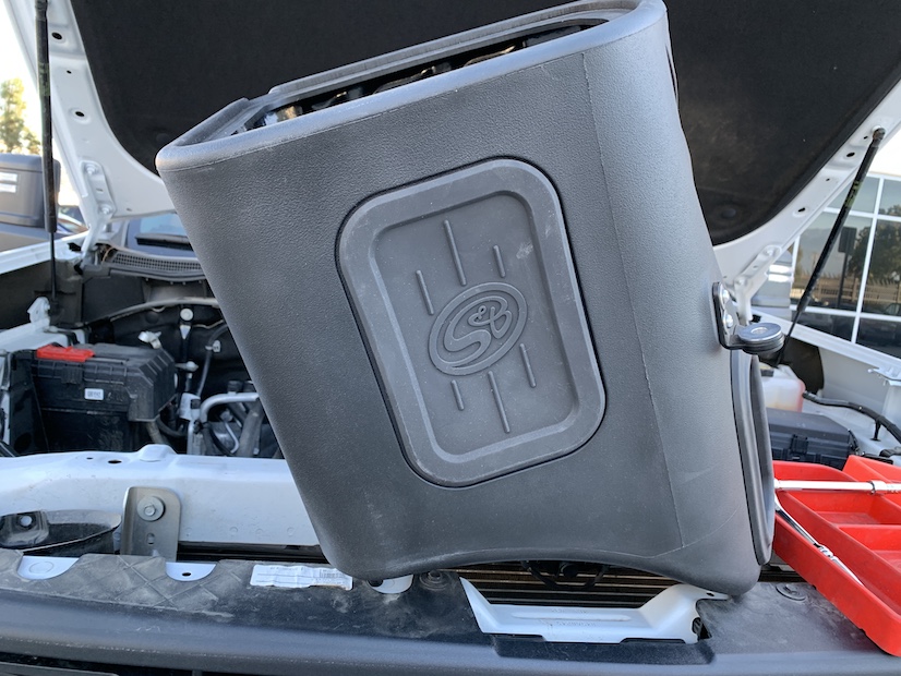
Install the Snap-In lid and lid seal into the airbox.
Use a 10mm socket to reconnect the ground.
To prevent the following message from displaying, the Air Filter Life system will need to be disabled.
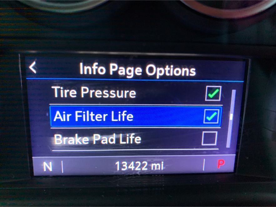
Navigate to the Options section of the Driver Information Center, and select the Info Page Options.
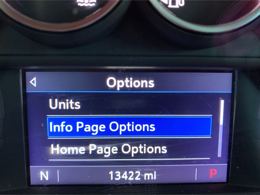
Ensure that the Air Filter Life has a green check mark next to it.
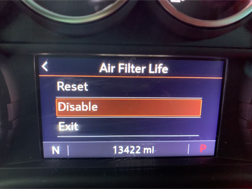
Navigate to the Info section of the Driver Information Center, and scroll down to the Air Filter Life section.
Press the wheel in to select the Menu for the Air Filter Life, and select Disable.
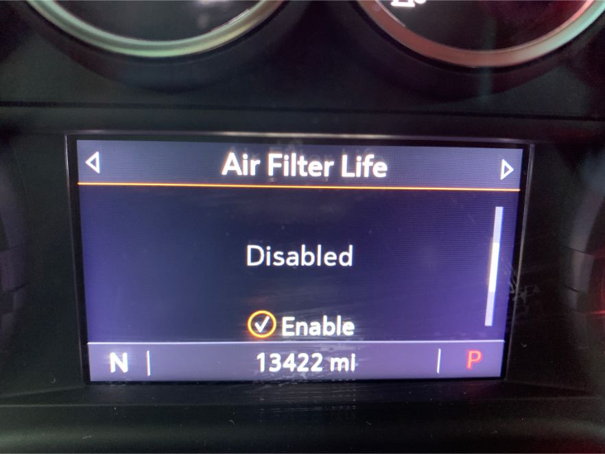
The screen should now display “Disabled”, as shown. Please verify the screen still shows disabled after the battery disconnect has been completed. If not, please repeat the process.
You can now move forward with the instructions to finish the installation of your new Cold Air Intake Kit.
The installation is complete. Inspect your installation, make sure the kit is properly positioned and all fasteners and hose clamps are secured. Affix the ID label near the intake kit. If you are an installer, give the owner the QR code for the Installation Instructions so that he/she is aware of the Maintenance and Operation procedures given in the beginning of the Instructions. The Installation is now complete.
