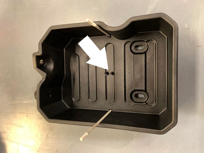
-BOM.jpeg?v=1686942362450)
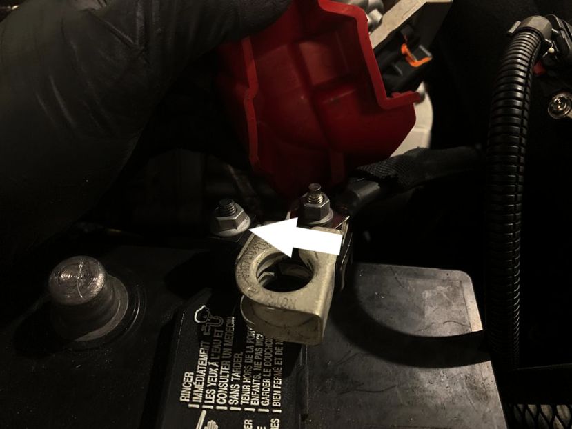
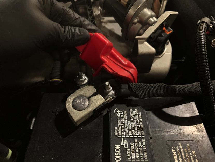
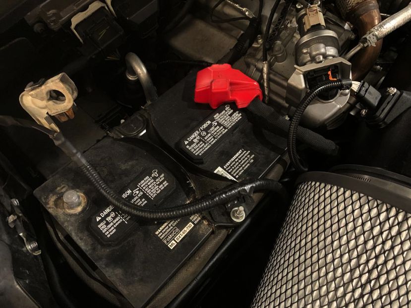
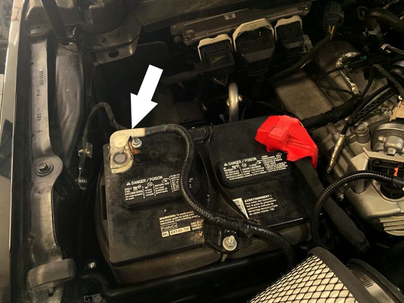
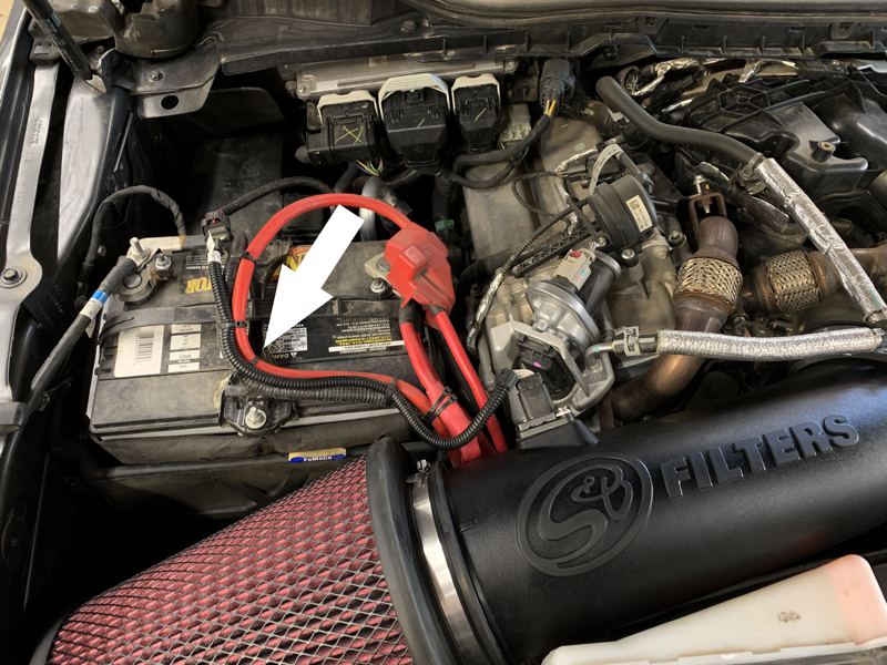
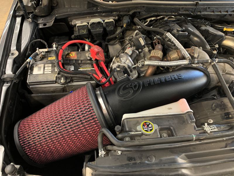
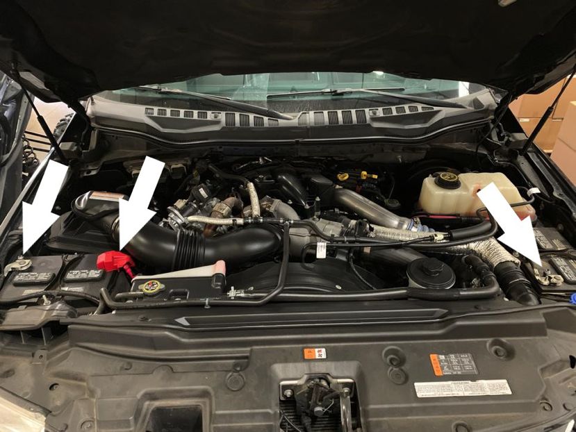
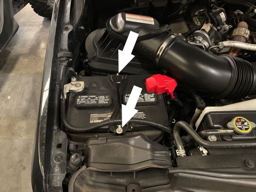
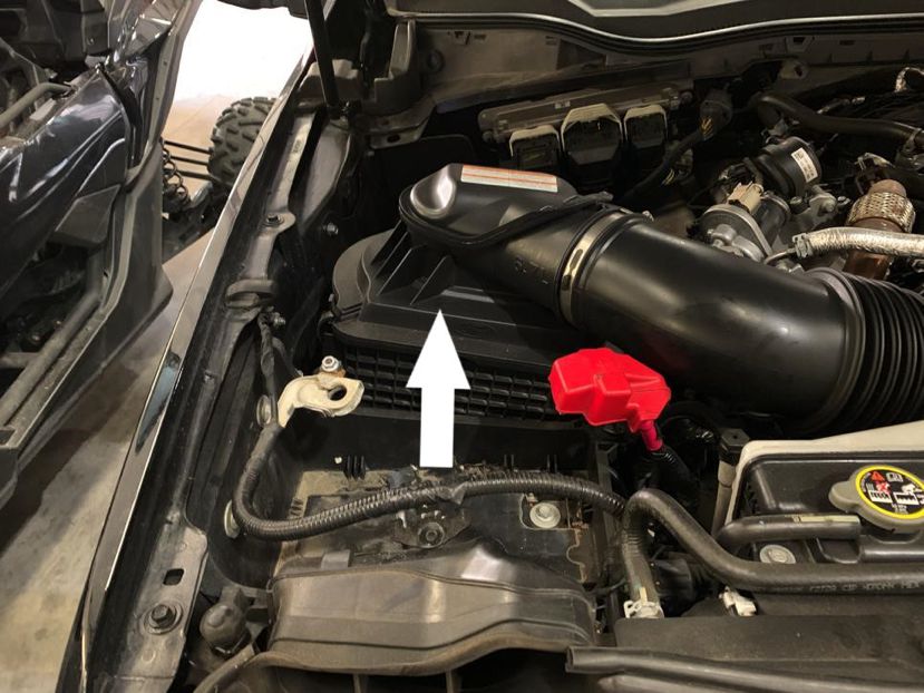
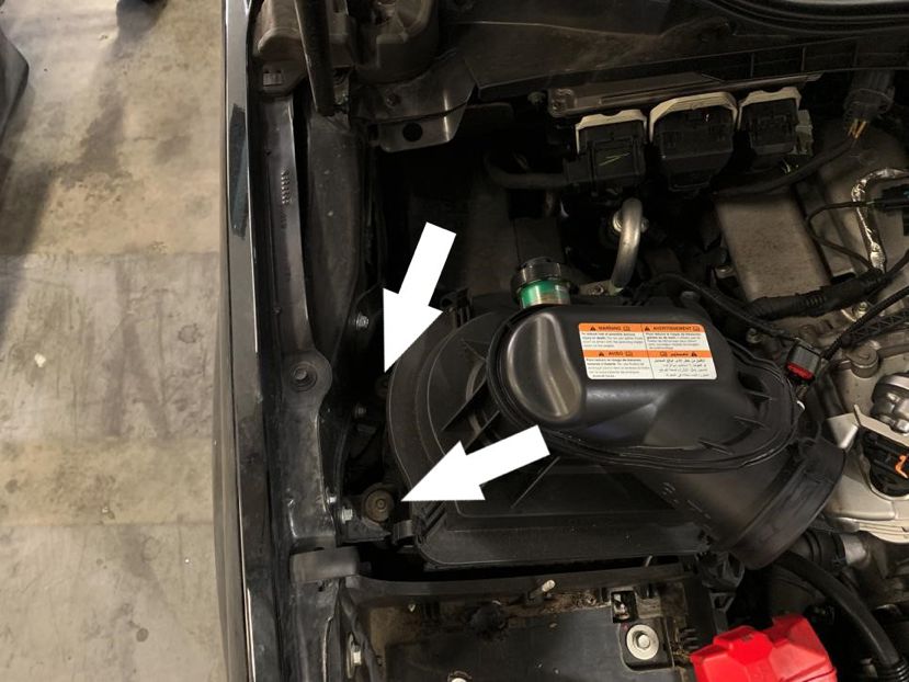
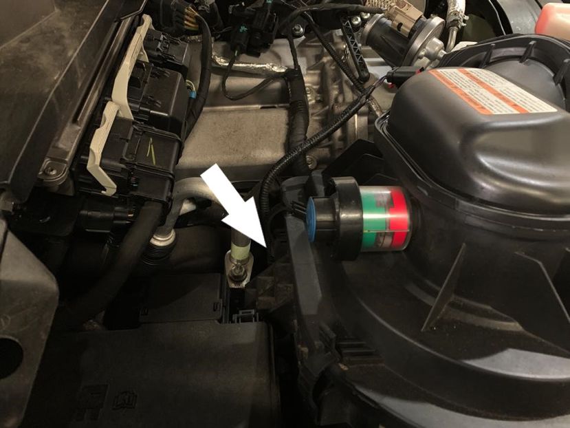
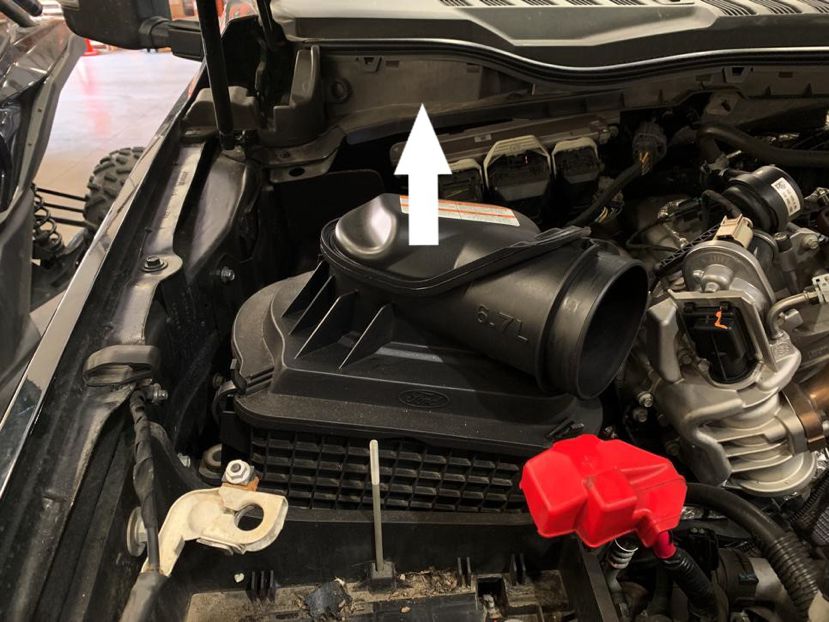
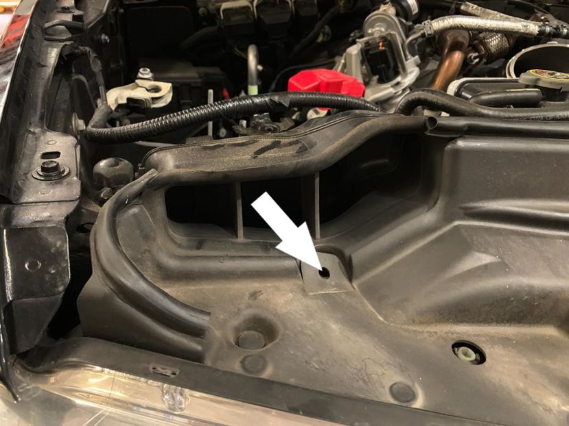
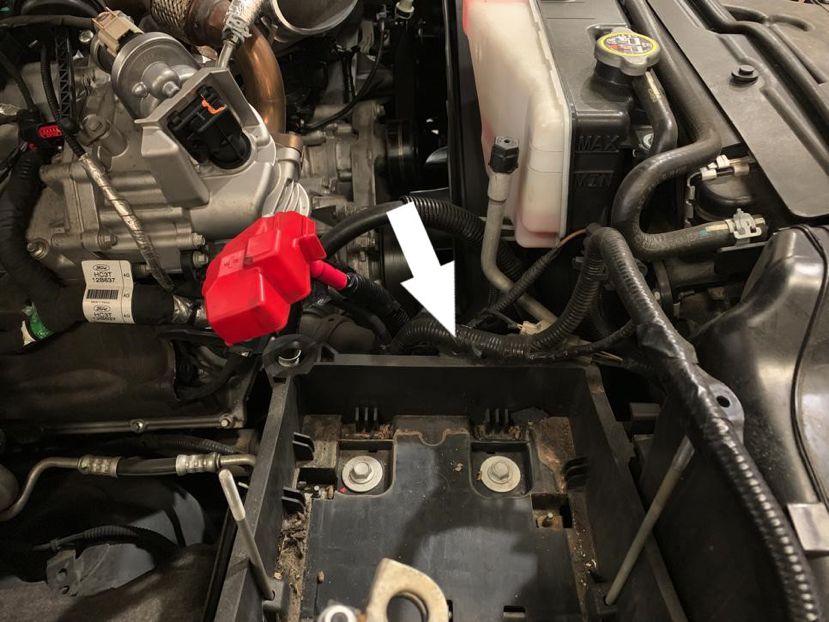
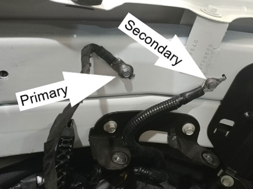
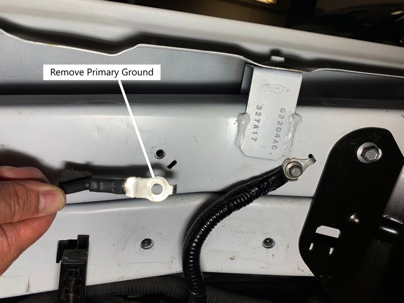
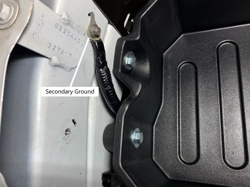
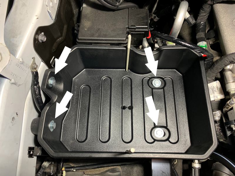
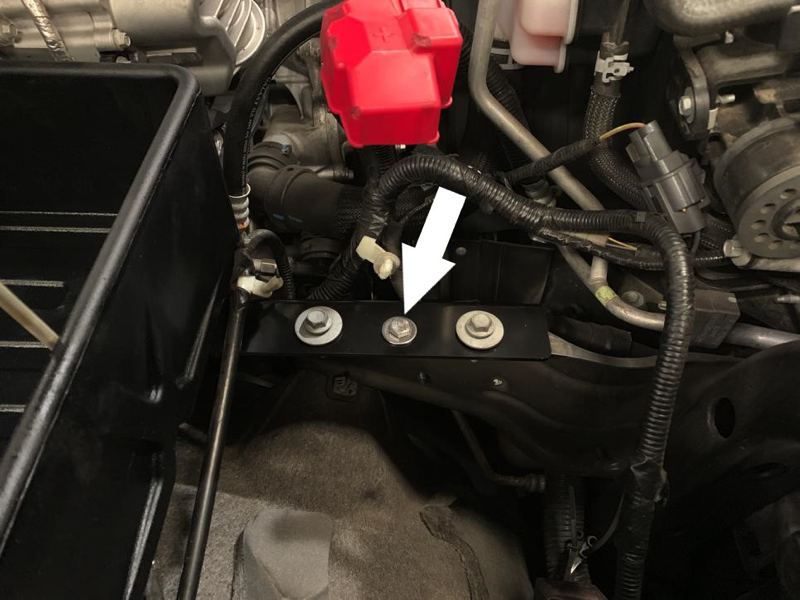
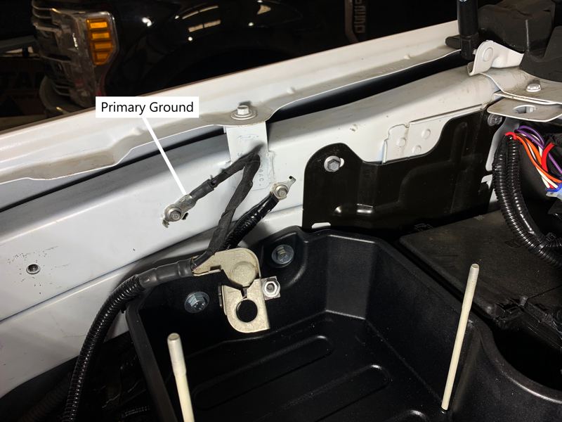
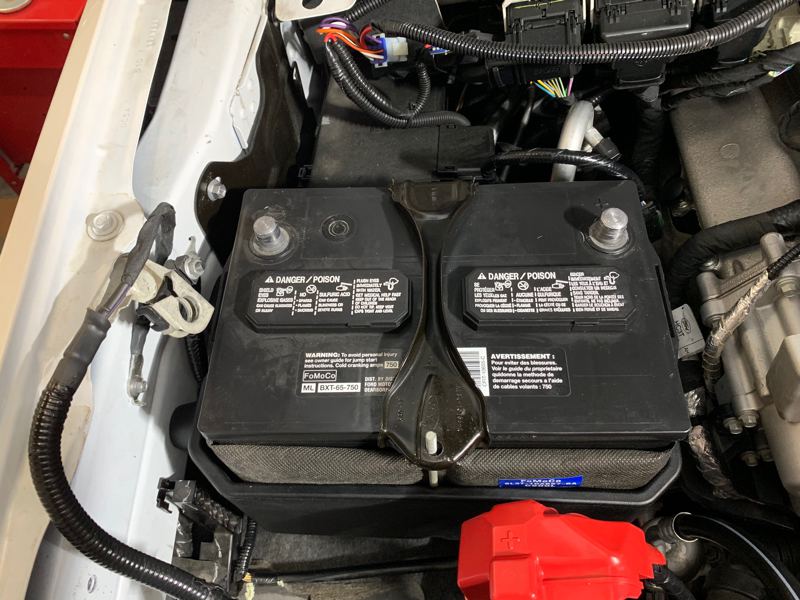
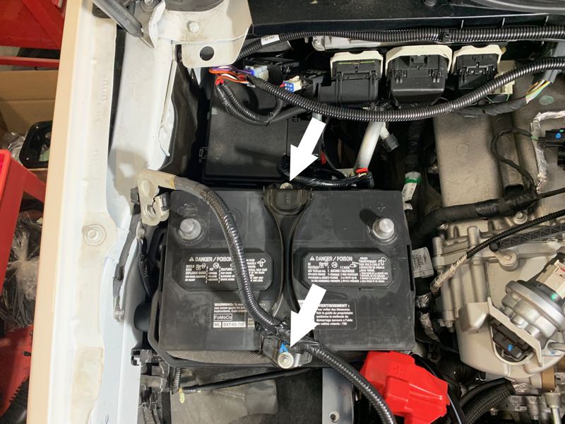
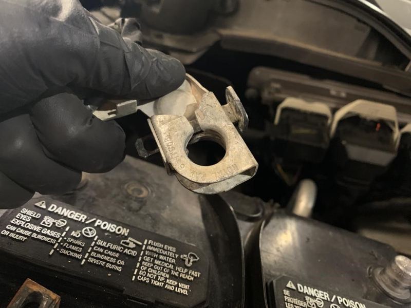
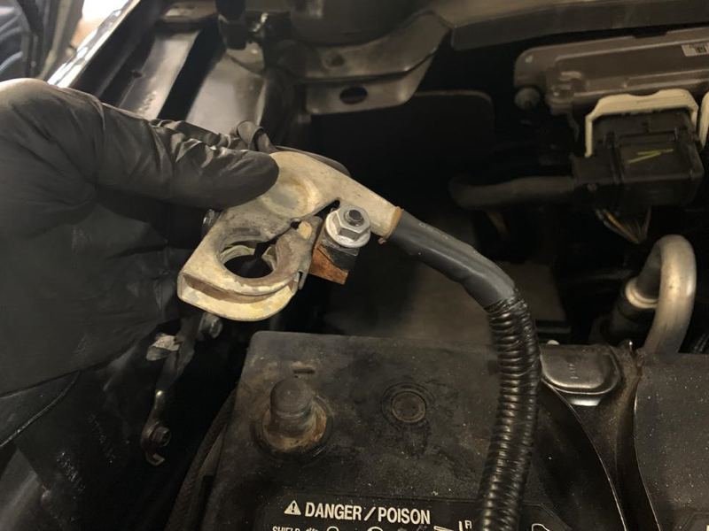
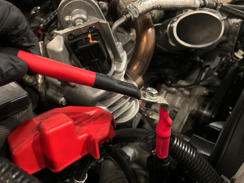
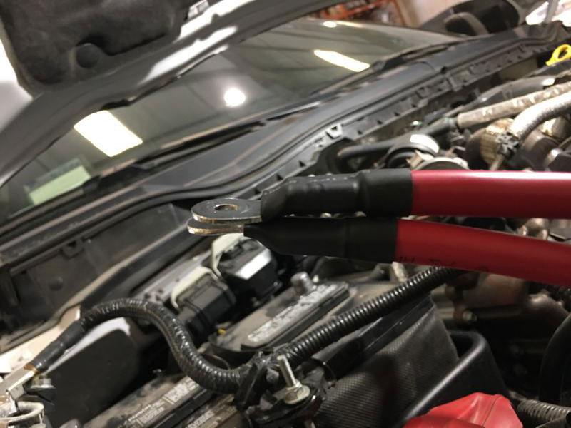
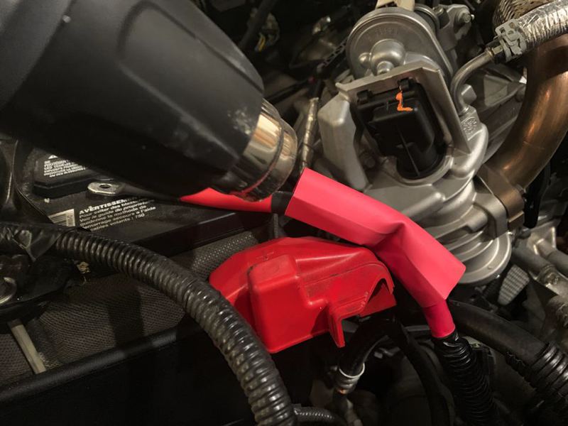
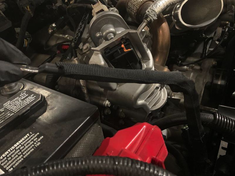
STEP 1
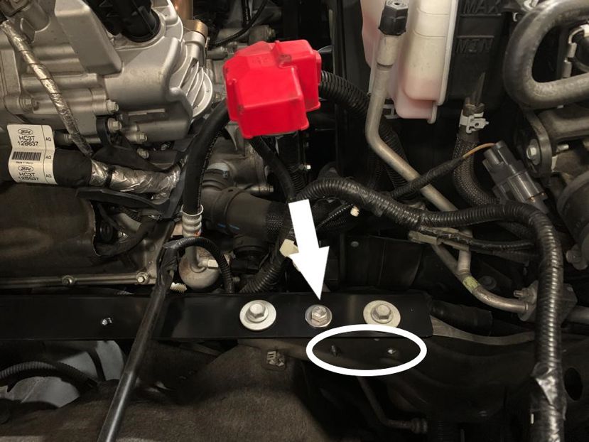
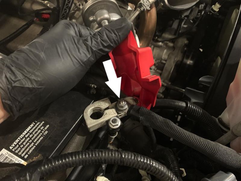
With the ignition switched off and the parking brake set, disconnect the negative battery cables on both batteries and positive battery cable on the passenger side only.
IMPORTANT: Failure to disconnect the battery for a minimum of 2 hours may cause the Check Engine Light to illuminate upon completion of the installation or subsequent operation.
DO NOT SKIP THIS STEP!
Tool Required: 10mm Socket, Socket Wrench.
.jpg?v=1686747286425)
.jpg?v=1686747475985)