STEP 1
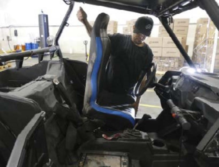
If you have a 2-seat RZR, remove both seats. If you have a 4-seat RZR, remove both the rear seats.
• Please read the entire installation manual before proceeding.
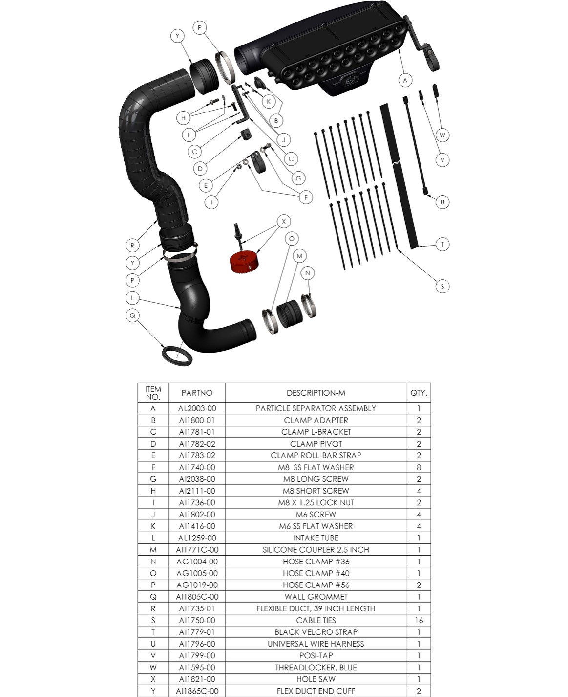
• Ensure all components listed on page 10 are present.
• If you are missing any of the components, call our customer support at (909) 947-0015.
• Do not work on the vehicle while the engine is hot.
• Make sure the engine is turned off, the vehicle is in Park and the Parking Brake is set.
2.5mm, 4mm, 5mm Hex Key
10mm, 13mm Wrench/Socket
5/16” Nut Driver
1/8”, 1/4” Drill Bit
Phillips Screwdriver
T40 Torx
Wire Cutters
Pilot Hole Punch
Tape
Razor Blade
Hole Saw (Included with Kit)
If you have a 2-seat RZR, remove both seats. If you have a 4-seat RZR, remove both the rear seats.
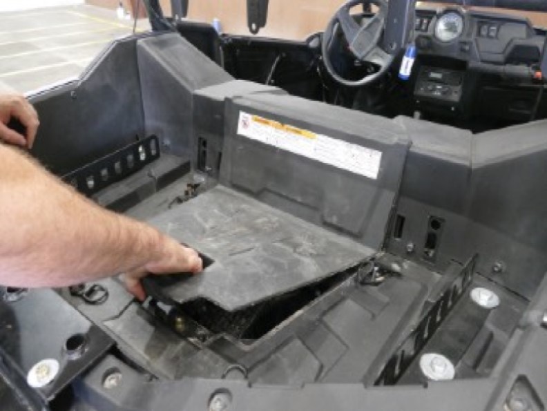
Pull up on the latch and remove the access panel in the cargo bed.
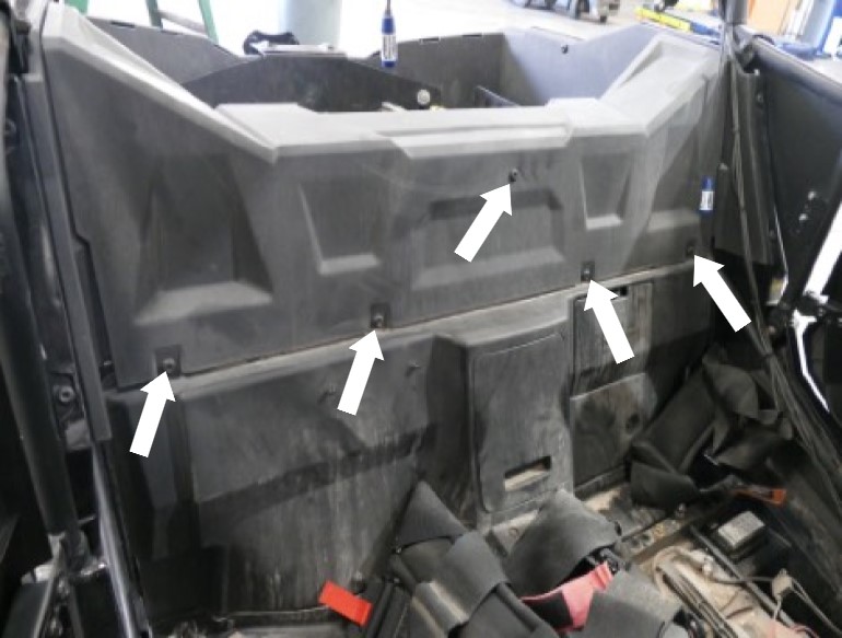
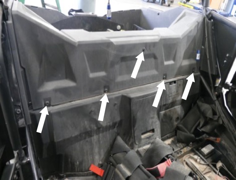
Remove the four screws on the air intake cover in the cargo bedside with a T40 Torx.
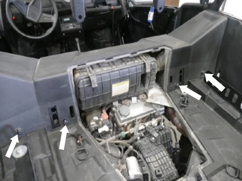
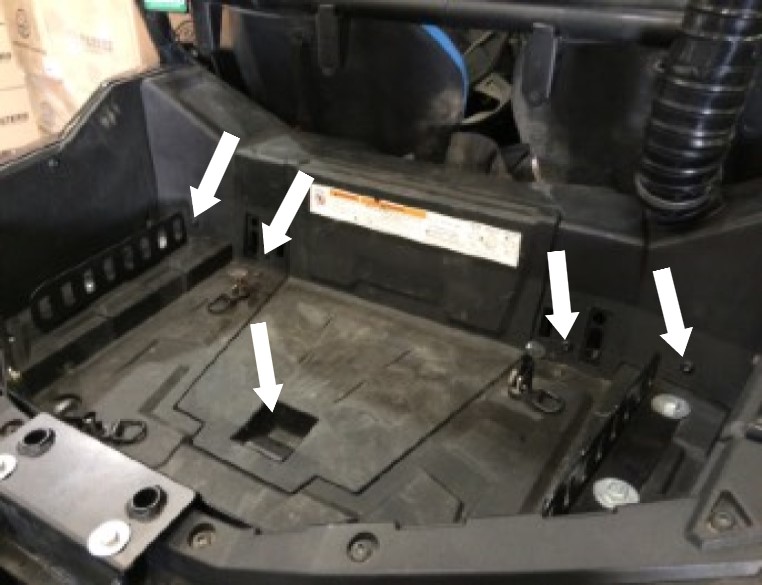
Remove the five screws on the air intake cover from inside the cab using a T40 Torx.
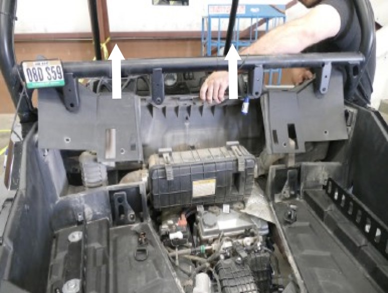
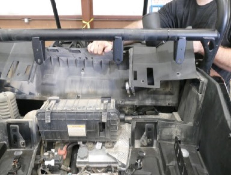
Lift up one side of the air intake cover and bend the cover slightly to get it past the seat belt tab. Do this for both sides. This removal will be easier if you have an extra pair of hands to help with the opposite side.
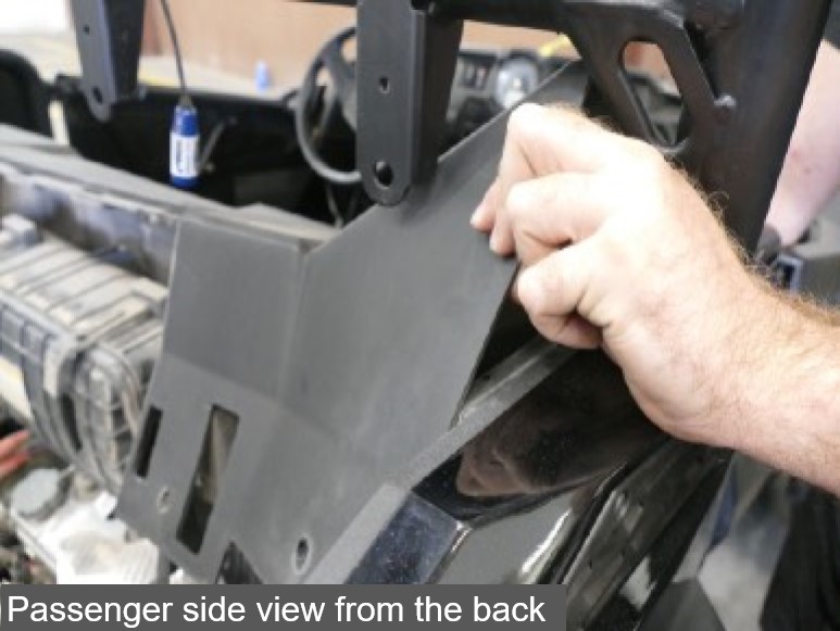
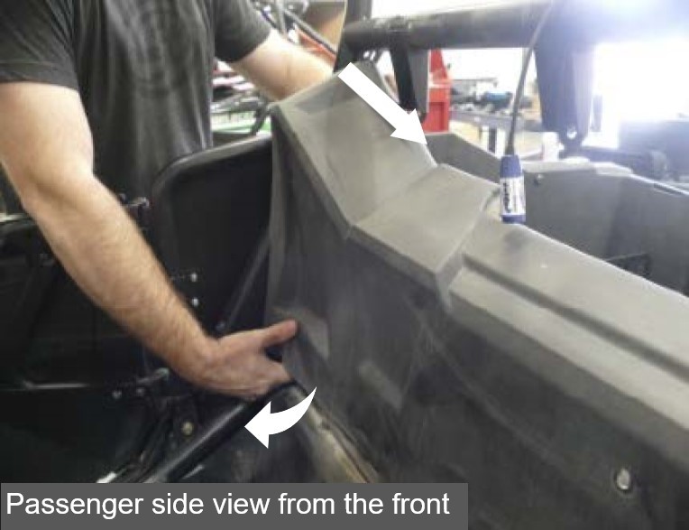
Once you clear the seat belt tabs, remove the air intake cover completely.
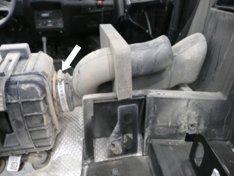
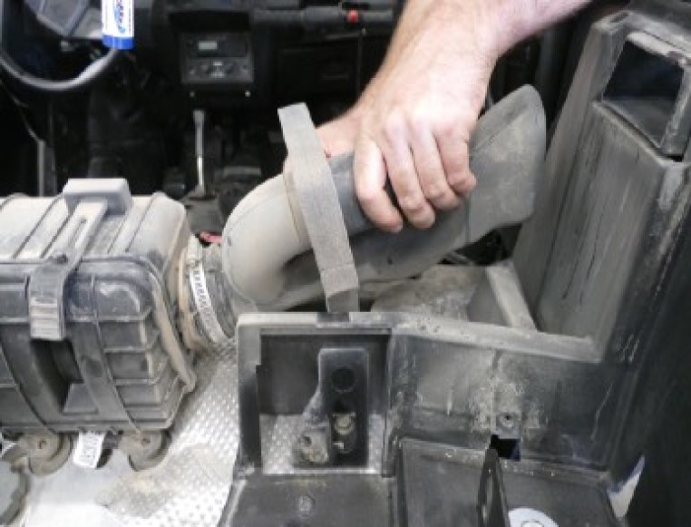
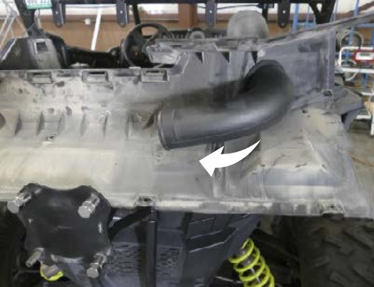
Loosen the hose clamp with a 5/16” nut driver or flat blade screwdriver and remove the stock intake tube.
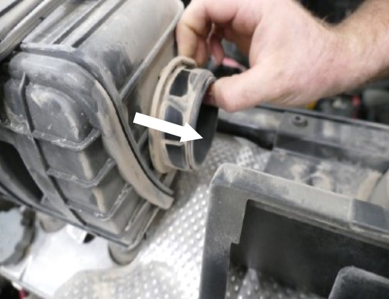
Remove the rubber coupler from the stock airbox.
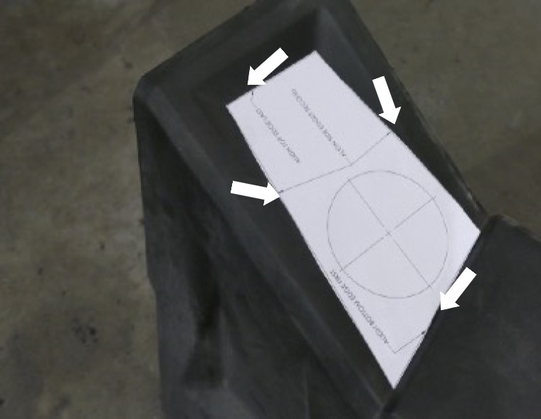
You will find a drill template. Cut out this drill template along the straight edges. This will be used to locate the correct drill location.
Line up the drill template with the edges on the passenger side of the air intake cover and use tape to secure the template.
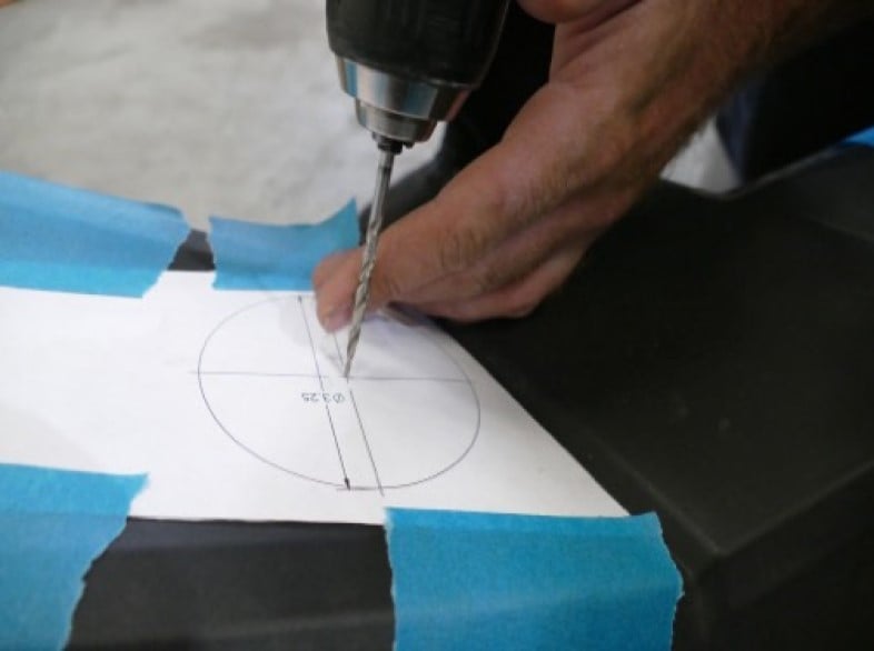
Use a 1/8” Drill Bit or Hole Punch to create your pilot hole. After the pilot hole is made, drill through the air intake cover with a 1/4” Drill Bit.
.jpg?v=1686920510480)
Attach the provided Hole Saw (X) and line up the saw with the template. Read the warning sheet before attempting to use the hole saw.
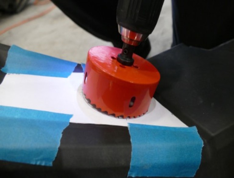
Start slowly and then progressively increase the speed. Doing so should give you a better cut. Try to keep the Hole Saw (X) as leveled as possible to the surface.
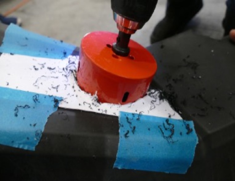
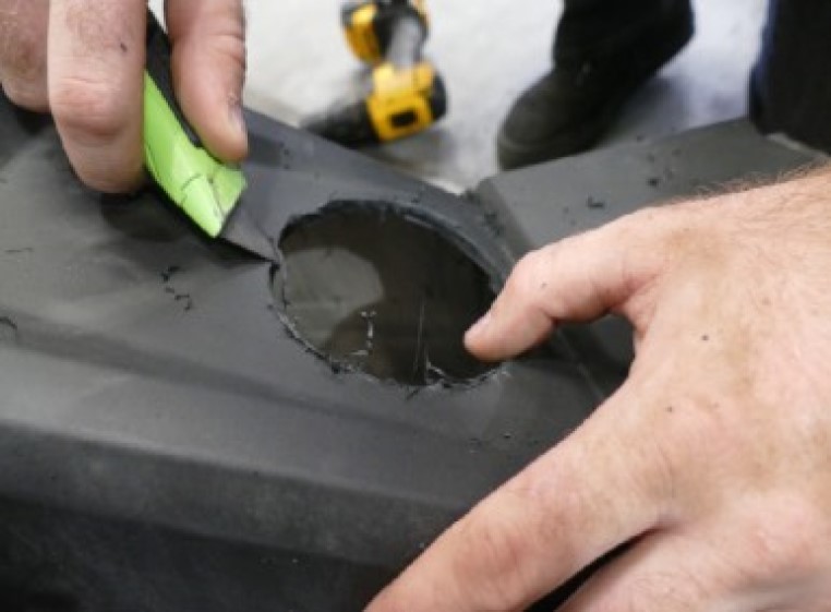
Remove the cutout template and use a knife or deburring tool to clean up the hole as best you can.
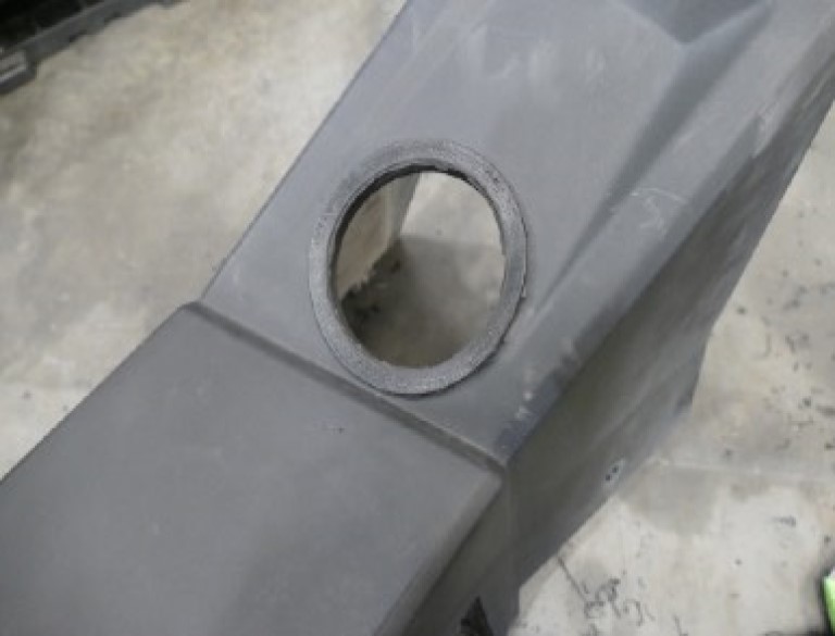
Insert the Wall Grommet (Q) into the hole.
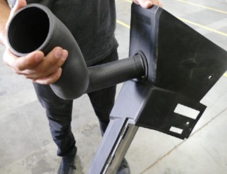
Insert the Intake Air Tube (L) through the Wall Grommet (Q) in the air intake cover. Stop when the tube hits the wall grommet. The tube should be facing the same direction as shown in the pictures below.
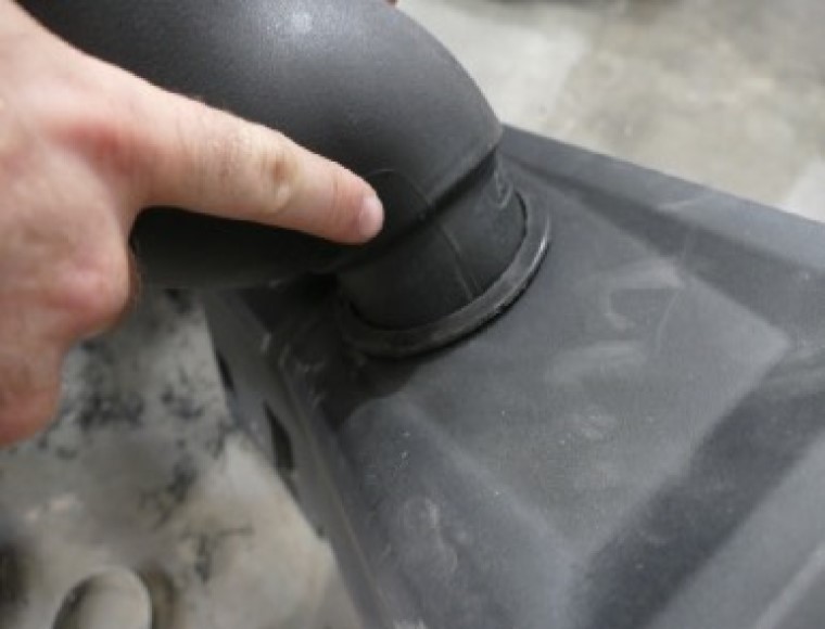
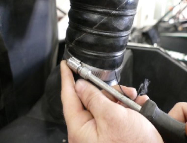
Insert the Coupler (M) with the #40 and #36 Hose Clamps (O & N) onto the Air Tube (L). Tighten the #40 Hose Clamp and leave the #36 Hose Clamp loose.
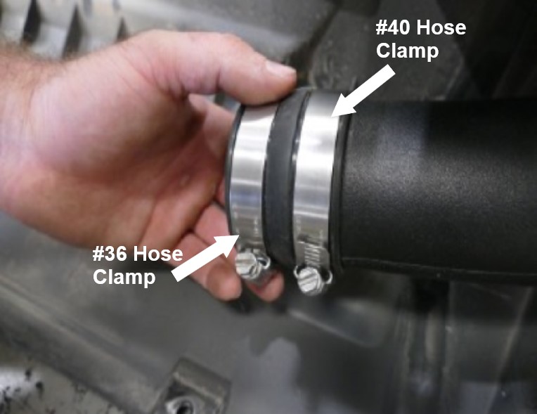
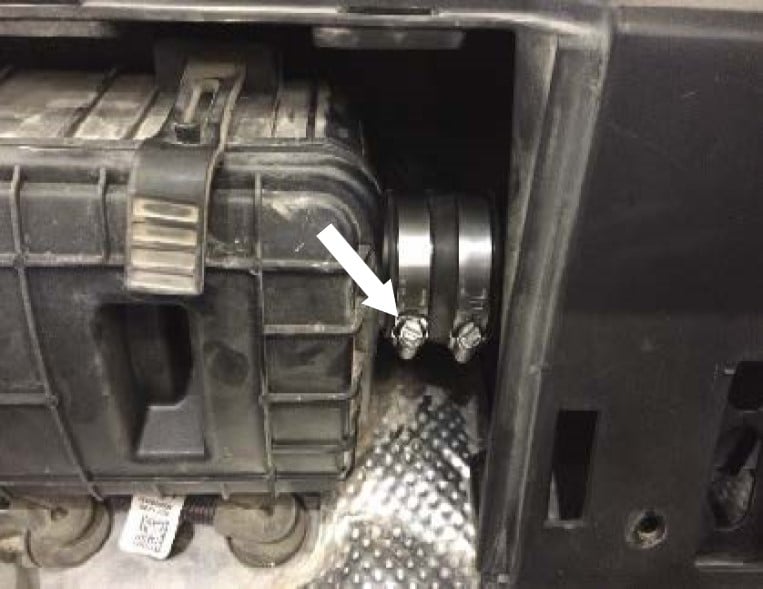
Reinstall the air intake cover. Install the Coupler (M) onto the stock air box inlet. Tighten the #36 Hose Clamp (N).
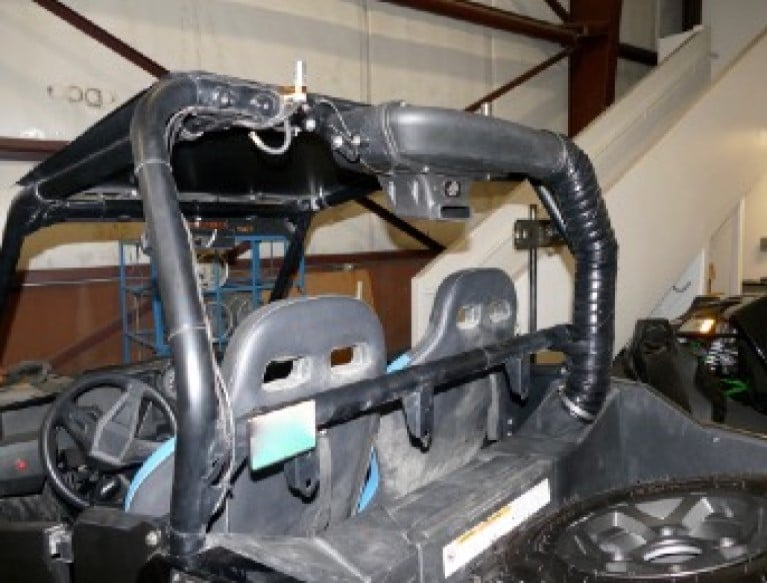
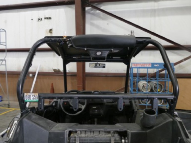
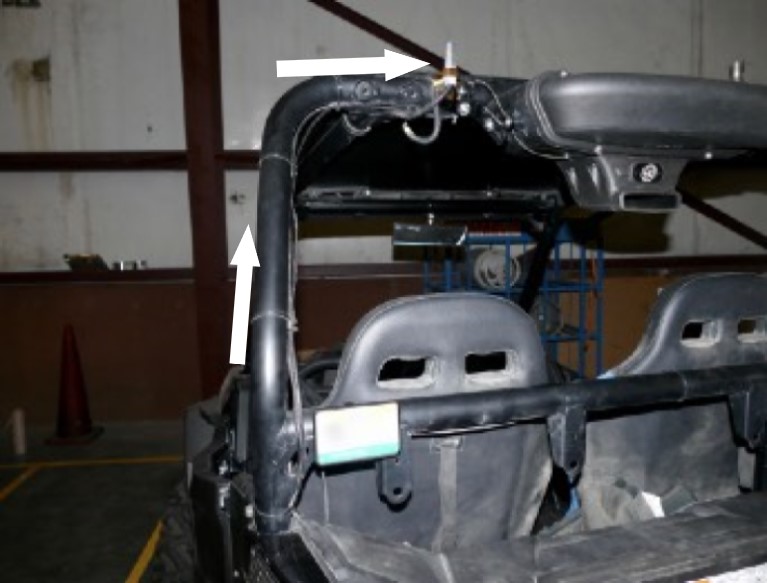
Determine where you would like to install the Particle Separator (A) on the roll cage, making sure you have enough room to fit the clamps and Particle Separatoron the roll cage without any interference Planning ahead will save you time during the install. Our clamps are adaptable enough to work around most accessories you may already have installed on the roll cage.
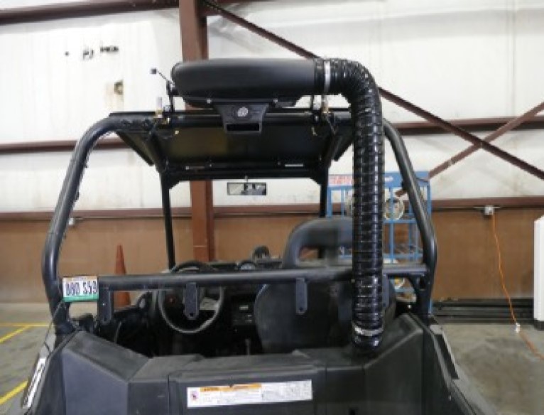
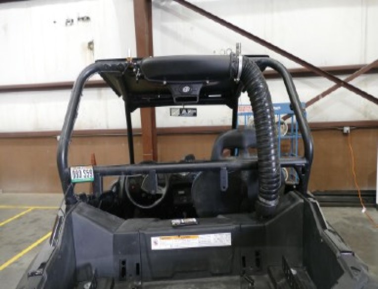
Once you have determined where you would like to install the Particle Separator, install the two Straps (D) onto the roll cage. Do not pull the ends of the straps open. Loosely wrap some plastic around the roll cage and push the straps onto the roll cage until they snap into place.
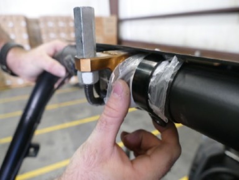
Install the Pivot Body (C) onto the Strap (D) with the supplied Screw (I), Locknut (J), and Washers (F) on the roll cage. Do not fully tighten the screws and locknuts. Leave the strap loose. Repeat for both clamps.
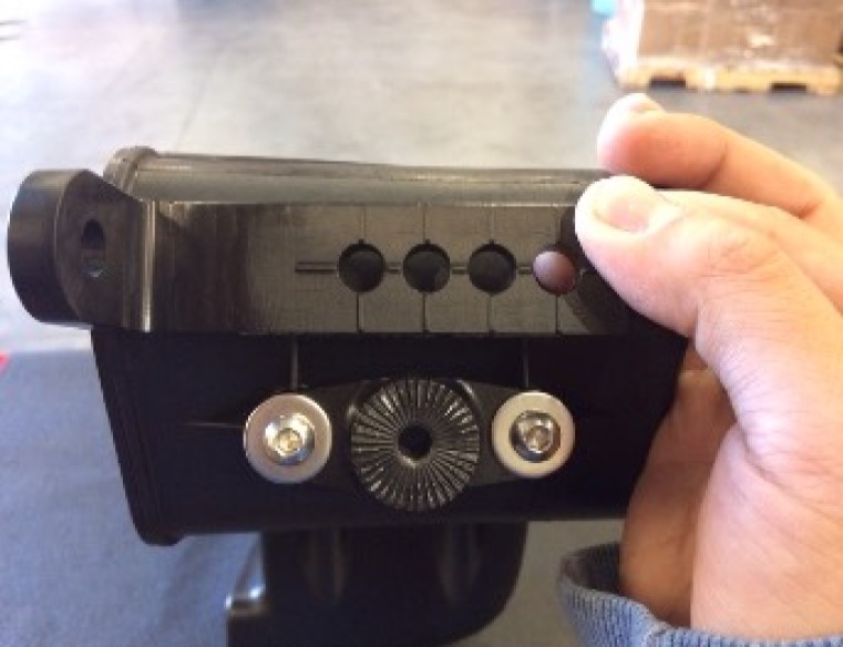
Install the Adapter (E) on the mounting bosses of the Particle Separator (A) with the supplied Screws (H) and Washers (F). Apply Threadlocker (W) to the screw before installing it. Tighten these screws. Repeat this for both sides.
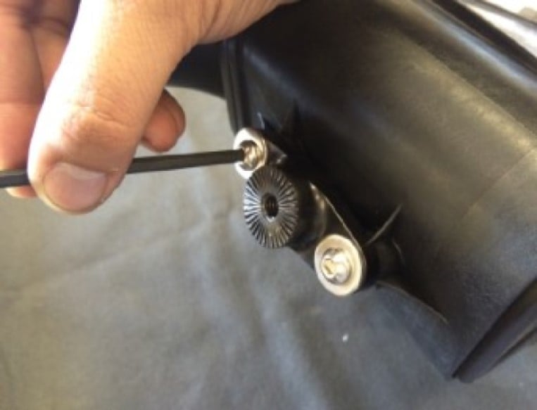
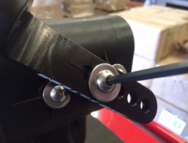
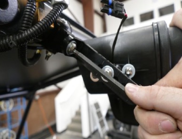
Determine the proper angle to mount the L Bracket to the Adapter based on the desired location for the Particle Separator (A). When installing the L Bracket (B), make sure the ribs in the L Bracket are properly seated inside the grooves of the Adapter (E). Do not attempt to rotate these parts once assembled. They are designed to lock into place once seated. Once you're satisfied with these configurations apply Threadlocker (W) to the Screw (K) then tighten with the Washer (G). Repeat for the other side of the Particle Separator and make sure the L Bracket on both sides are pointed in the same direction and are aligned with each other.
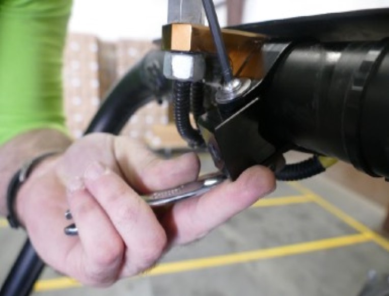
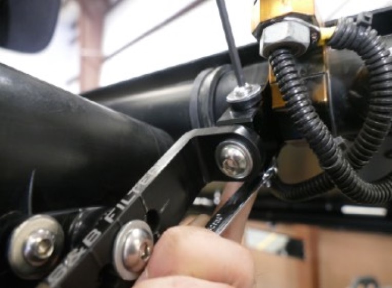
Install the L Bracket (B) onto the Pivot Body (C) using Screw (K) and Washer (G). Apply Threadlocker (W) to the screw before installing it. You may have to adjust the position of the Strap (D) and pivot body to get the holes to line up. Do this for both sides. Having an extra pair of hands holding the Particle Separator (A) to help line up the holes will make the install easier.
Once you are satisfied with the position, tighten the Screw (I), Locknut (J), and Washer (F) to secure the Strap (D) at the roll cage. Do this for both sides.
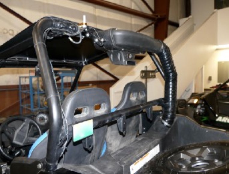
Double-check that all screws and locknuts are tight and that they are securely holding the Particle Separator (A) assembly to the roll cage.
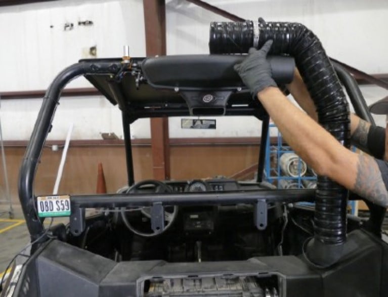
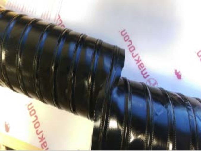
Insert one end of the Duct (R) onto the Intake Air Tube (L), do not tighten. Bring the other end towards the plenum on the Particle Separator (A). Note the length needed to reach the clean air plenum on the Particle Separator. We recommend adding an extra 3” more to the length of the duct needed.
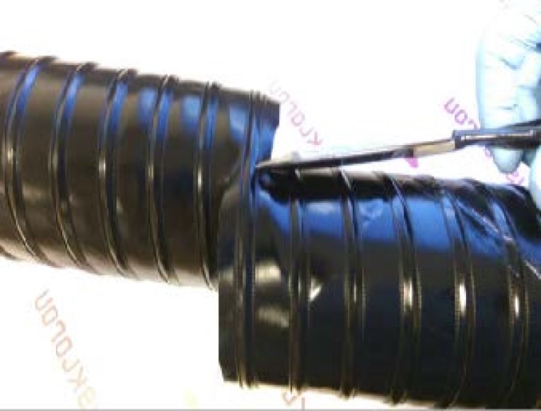
Pierce the Duct (R) using a razor, centered between the two-wire reinforcements. Cut all the way around, keeping the blade centered between the wire reinforcements the entire length of the cut. Use a mini bolt or a heavy-duty wire cutter to cut through the wire and duct. Use a pair of scissors to cut through any remaining duct not yet cut.
(Optional) Regular staples can be used to secure the ends of any loose strings hanging from the Duct (R).
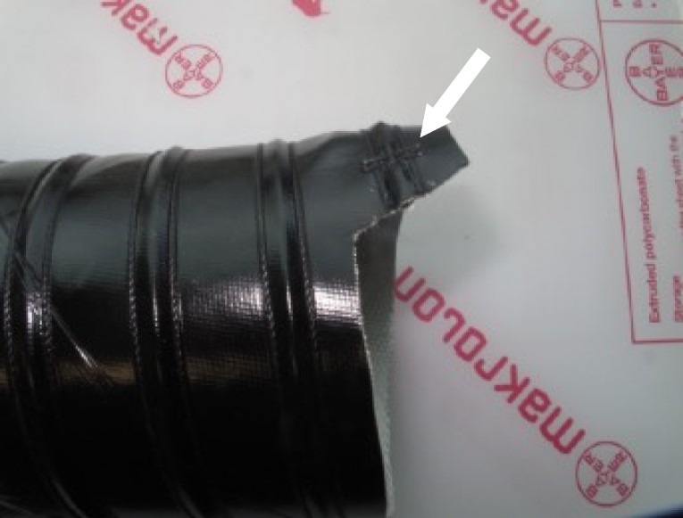
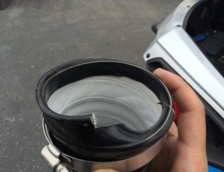
(Optional) For a cleaner appearance, take the end of the wire and tuck it inside the duct. Do this for both ends of the duct if needed.
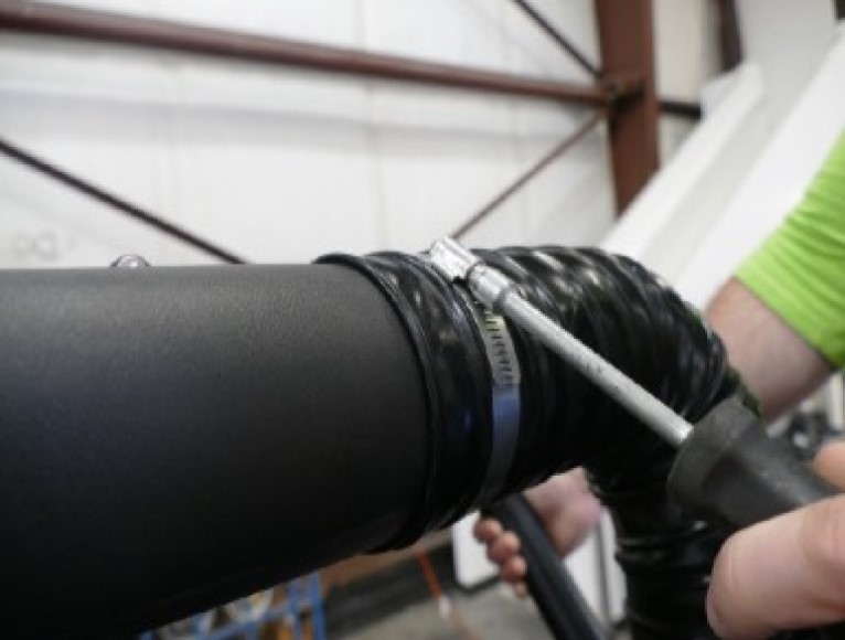
Install the Duct (R) onto the Intake Air Tube (L) and tighten Hose Clamp #56 (P).
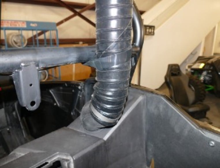
Install the end of the Duct (R) onto the plenum on the Particle Separator (A). Tighten Hose Clamp #56 (P).
Use the provided Velcro Strap (T) or Cable Ties (S) to secure the Duct (R) to the roll cage.
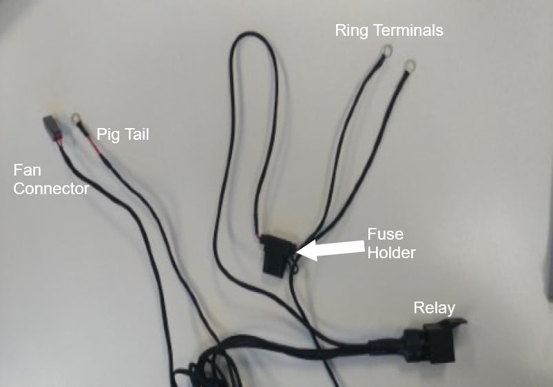
Familiarize yourself with the Wire Harness (U) and each of the connectors. Coming from the relay should be a pigtail, fan connector, and ring terminals. Pig Tail Wire is used in conjunction with the Posi-Tap (V) to tap into a power source. Ring Terminals has the fuse holder with the red and black ring terminals for the battery. Fan Connector has the connector to power the Particle Separator (A).
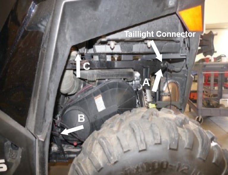
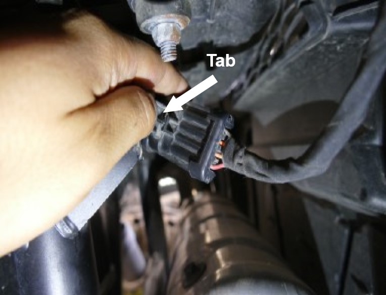
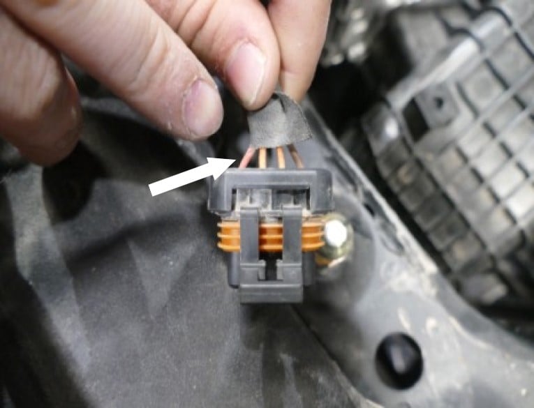
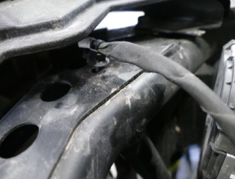
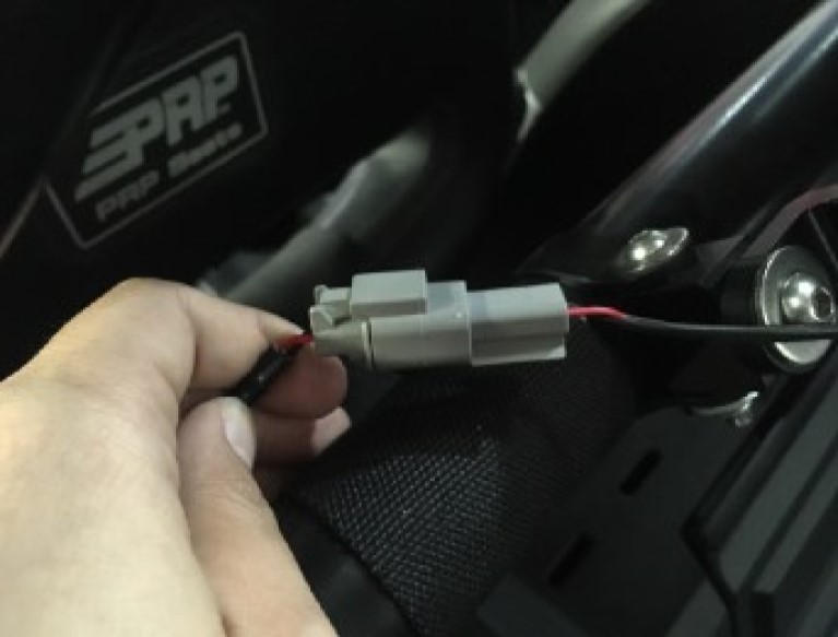
Find and disconnect the taillight connector. Lift up on the tab and pull the connector off.
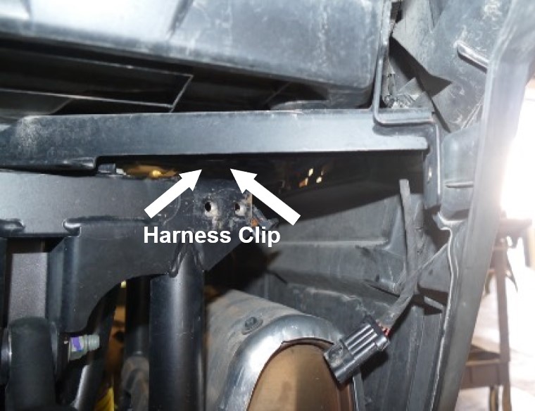
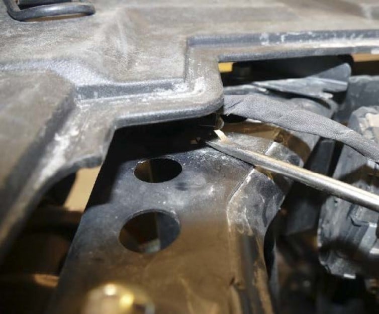
Follow the male end of the taillight connector back and find the harness clip connected to the frame. You can remove the harness clip from the top through the access panel on the cargo bed. Use a flat head or panel popper to remove this clip. Be careful not to damage the clip. If damaged, the clip may not be reusable. Removing the clip is not necessary but will help make the install easier.
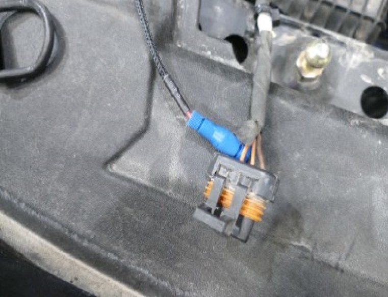
Take a look at the connector. You will be tapping into the red wire.
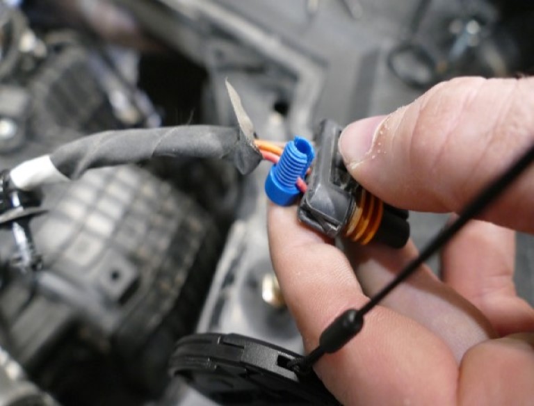
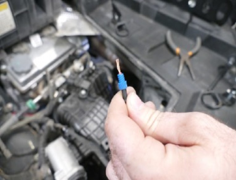
Use the supplied Posi-Tap (V) and unscrew the large top cap. Place the cap in between the red wire on the taillight connector. This will be your power source. Then screw the body around the cap until it is firmly tight.
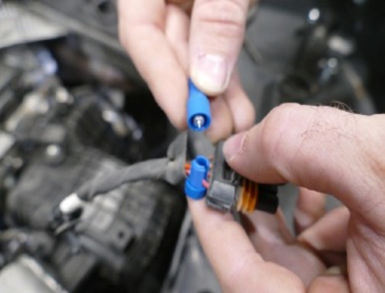
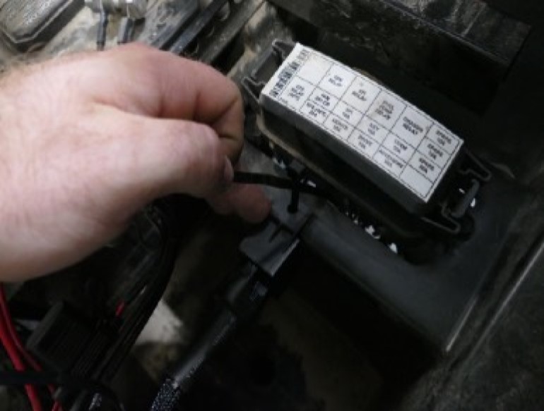
Find the pig tail, from the Wire Harness (U), and strip about 3/8” off the end of the wire. This would be the best time to route and tuck the wire in the rear end of the vehicle.
Unscrew the bottom cap on the Posi-Tap (V) and insert the pigtail through it. Then insert the wire into the main body of the Posi-Tap, making sure the strands go around the metalcore. While holding the wire in place, screw the bottom cap back on until it is firmly tight. Double-check both caps to make sure they are tight.
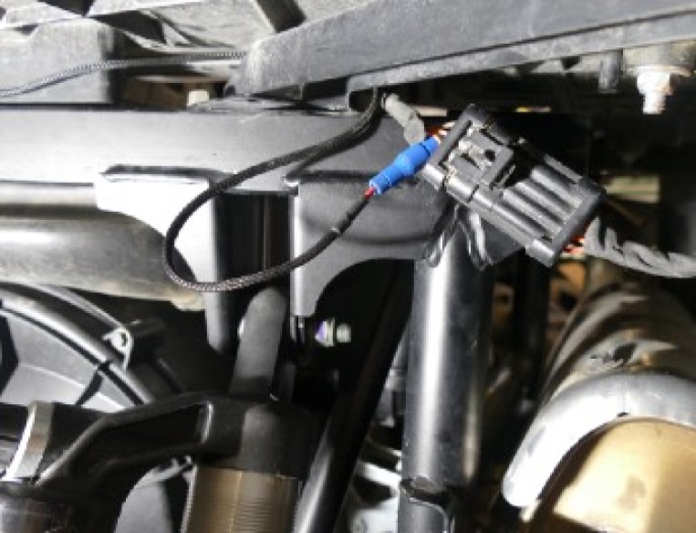
Feed the connector back through the access panel and back down to where it was originally located. Snap the harness clip back onto the frame.
Reconnect the taillight connectors. Use the provided Cable Ties (S) to secure the wire to the roll cage. Use cable ties effectively to secure the harness away from any exhaust components or moving parts that could potentially damage the harness.
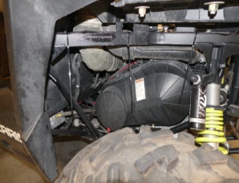
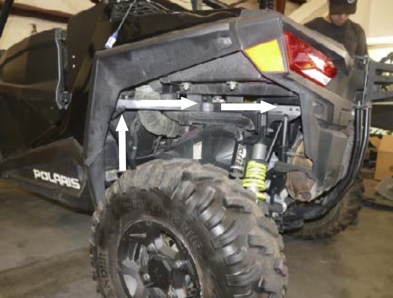
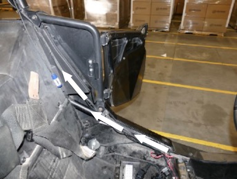
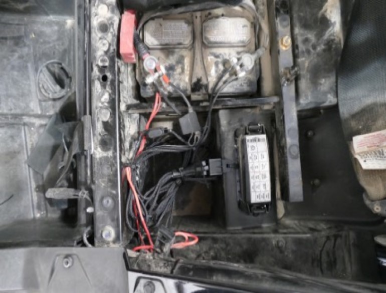
Feed the relay, terminals and fuse holder through the gap behind the rear driver’s side fender. This gap goes to the battery compartment.

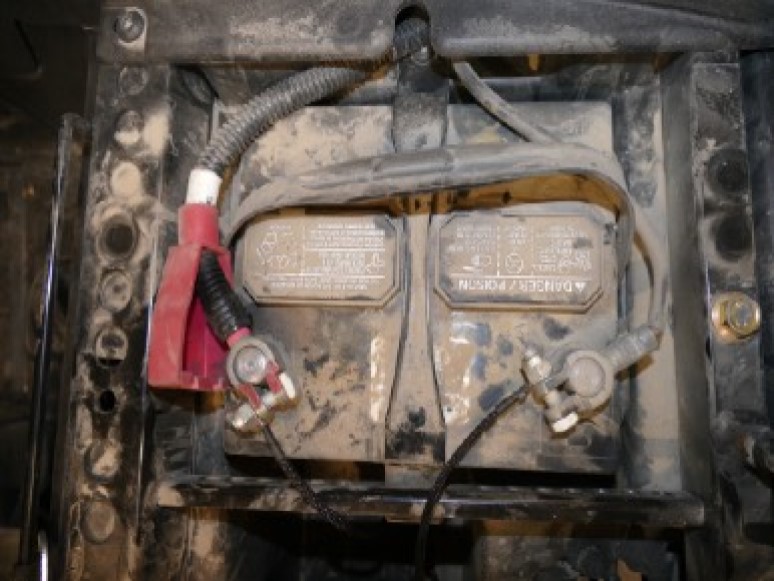
Loosen and remove the nut on the negative battery terminal, then disconnect the terminal from the battery. Repeat for the positive battery terminal. Install the ring terminals, from the Wire Harness (U), onto the battery terminal clamps. Red wire with the fuse holder to (+) and Black wire to (-) and reinstall the nuts. Secure the positive terminal first and then secure the negative terminal.
To ensure that you have installed the Wire Harness (U) correctly, connect the Fan Connector to the Particle Separator (A). Note the color of the wires whenever connecting or disconnecting this connector. Make sure not to cross the connectors. Power (red) to power (red) and ground (black) to ground (black). The connector should snap into each other with very little resistance. Do not try to force the connectors into each other.
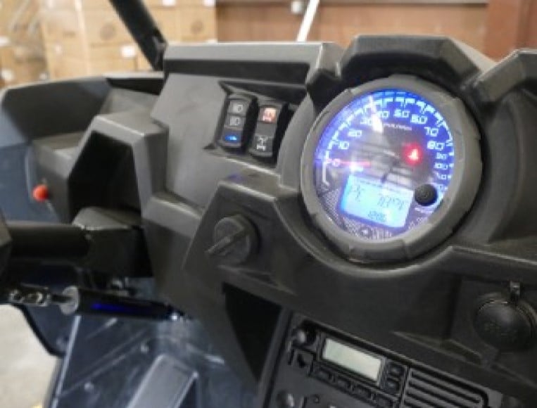
Turn on the ignition and see if the particle separator turns on. If you hear the Particle Separator fan turning on, you have installed it correctly. Proceed to the next step.
From the battery compartment route Connector C up the roll cage. Connect the harness into the fan connector on the Particle Separator (A).
Use the Cable Ties (S) or Velcro (T) provided to secure the wire to the roll cage.
Group together any excess wires and Cable Tie (S) them together. Use another cable tie and secure the bundle in places away from any exhaust components or moving parts that could potentially damage the harness.
Reinstall the five screws into the air intake housing inside the cab. Loosely tighten each screw to make sure you can get the screws in before fully tightening. Reinstall the seats.
Reinstall the four screws at the cargo bed. Loosely tighten each screw to make sure you can get the screws in before fully tightening. Reinstall the access panel.
Make sure the connectors are all plugged in and secure. Turn the ignition on and make sure air is blowing out the exhaust. If the exhaust fan does not turn on, double check your electrical connections. When you turn the ignition off, the fan will stay on for several seconds and is normal. Your installation is now complete.