STEP 1
Look under the driver’s seat. Pull the seat adjuster and move the seat forward as far as possible.
• Please read the entire installation manual before proceeding.
• Ensure all components listed on page 10 are present.
• If you are missing any of the components, call our customer support at (909) 947-0015.
• Do not work on the vehicle while the engine is hot.
• Make sure the engine is turned off, the vehicle is in Park and the Parking Brake is set.
Look under the driver’s seat. Pull the seat adjuster and move the seat forward as far as possible.
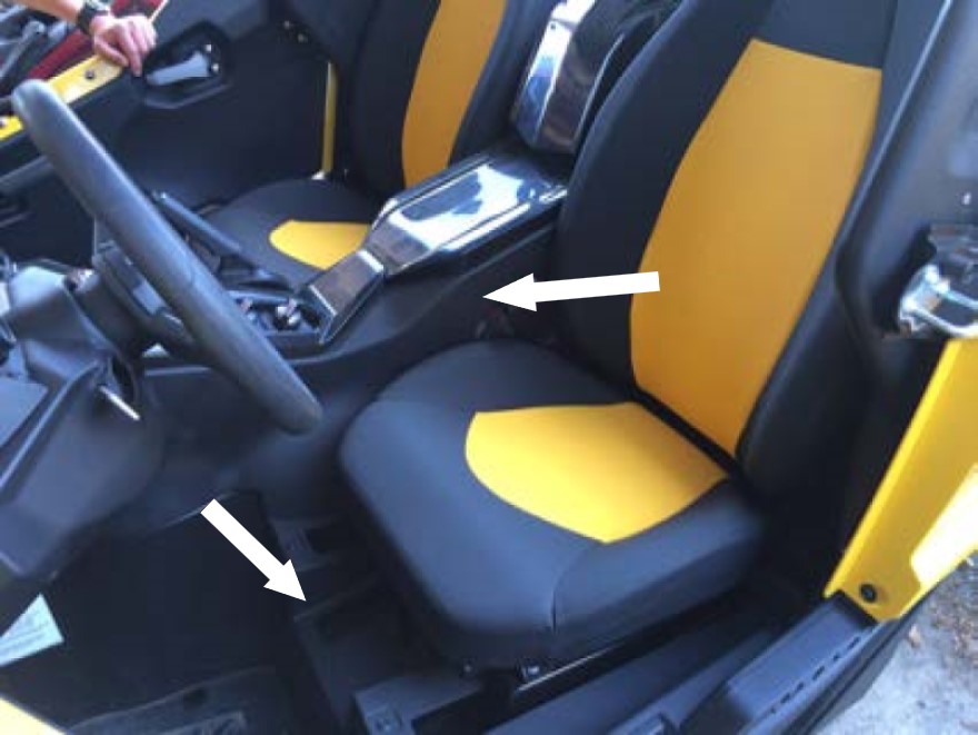
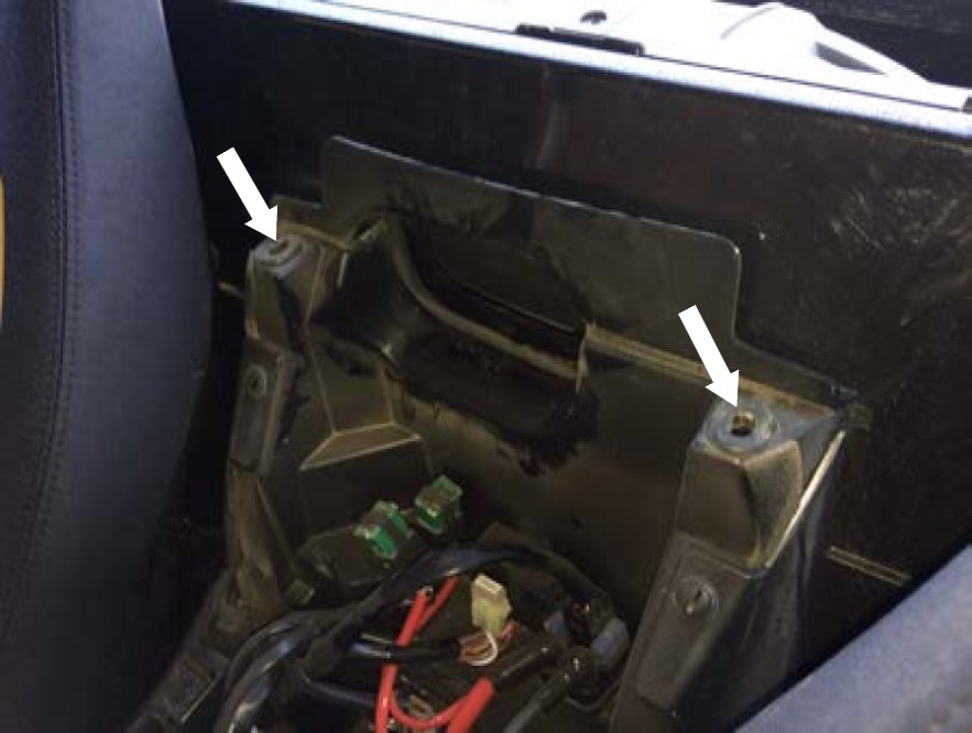
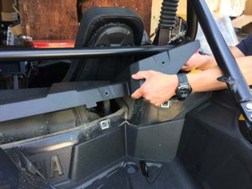
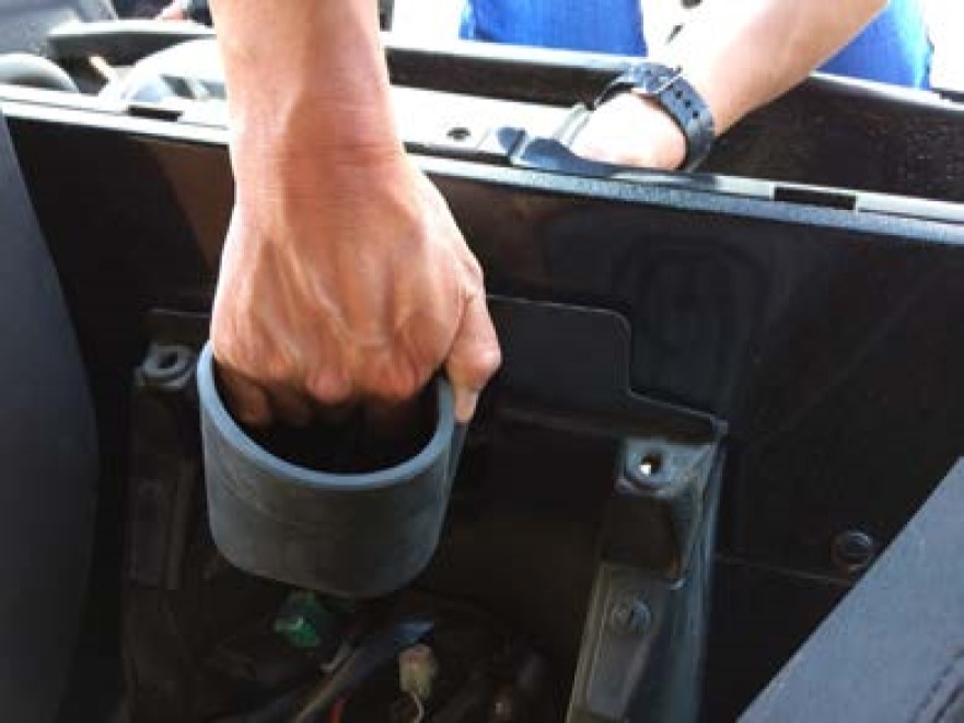
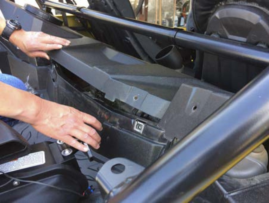
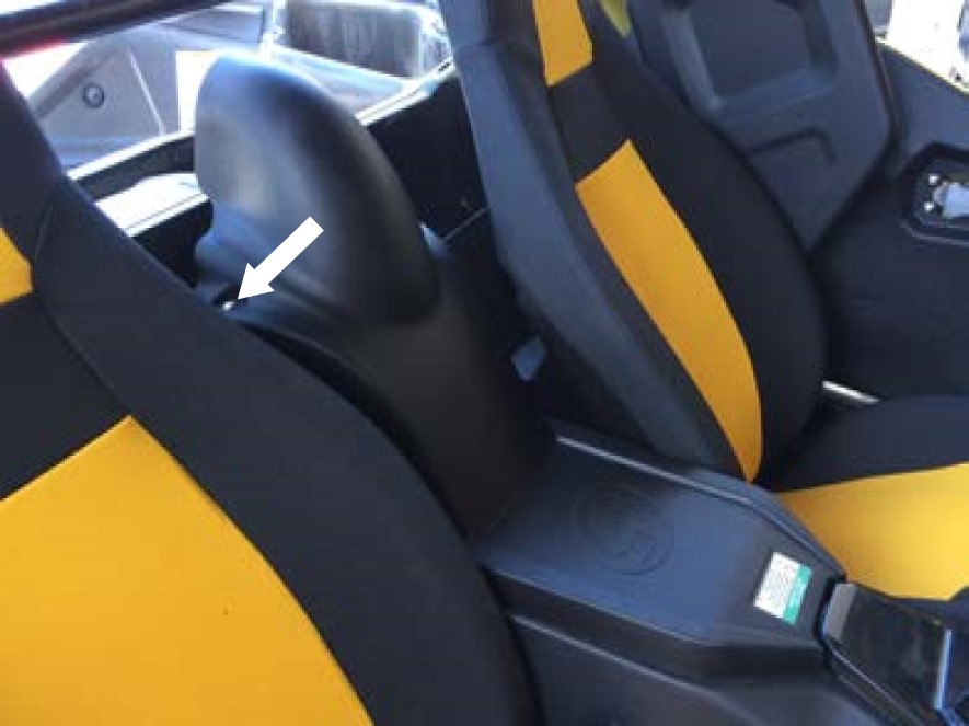
Remove the center console cover by lifting up and sliding the tab out from its slot.
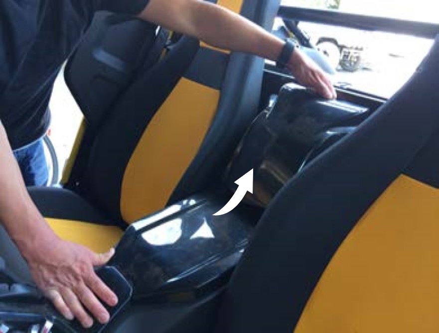
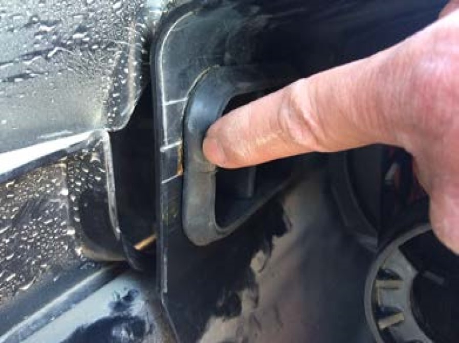
After removing the center console, make sure the grommets didn’t come off with the cover or fall out of place.
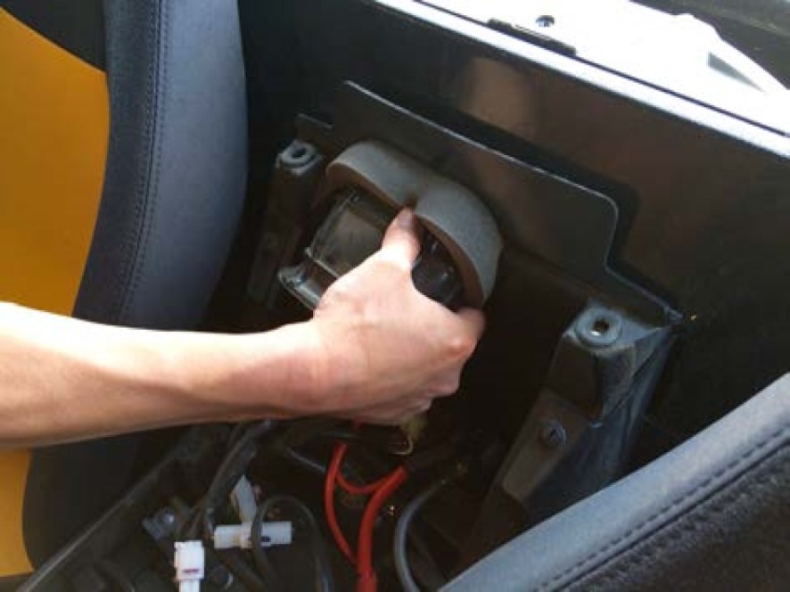
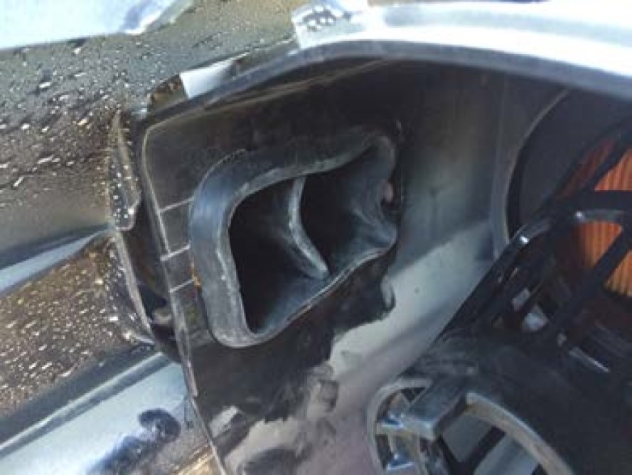
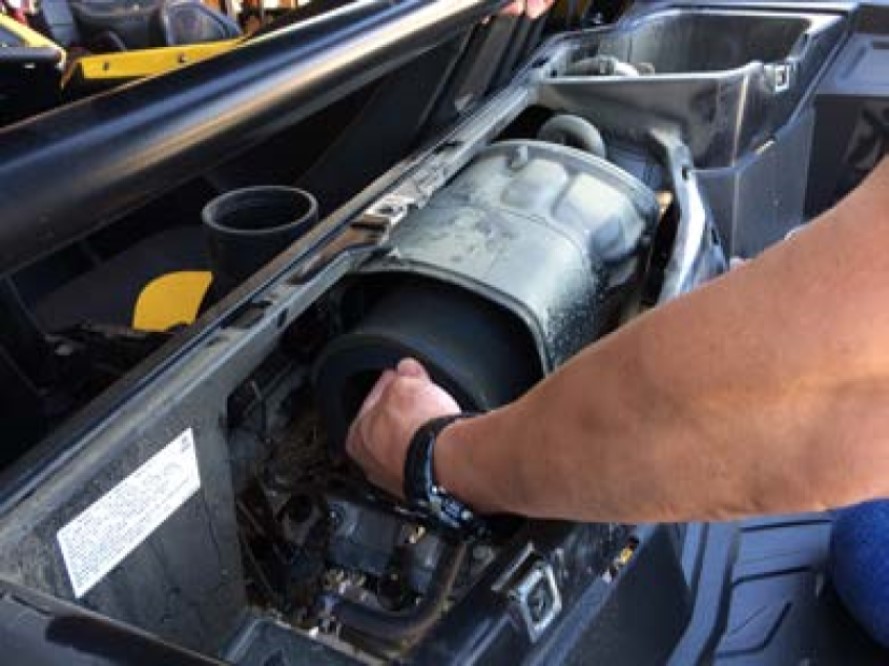
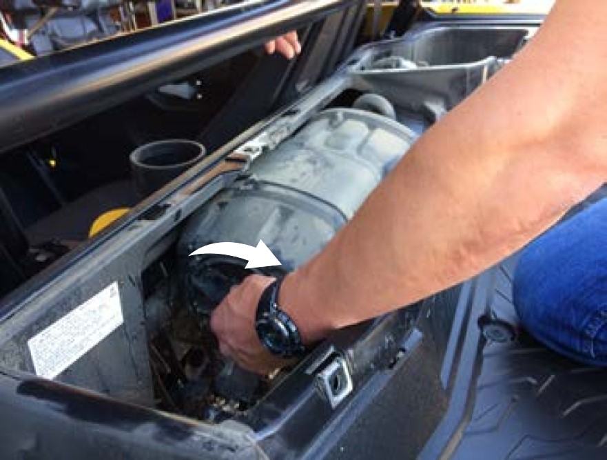
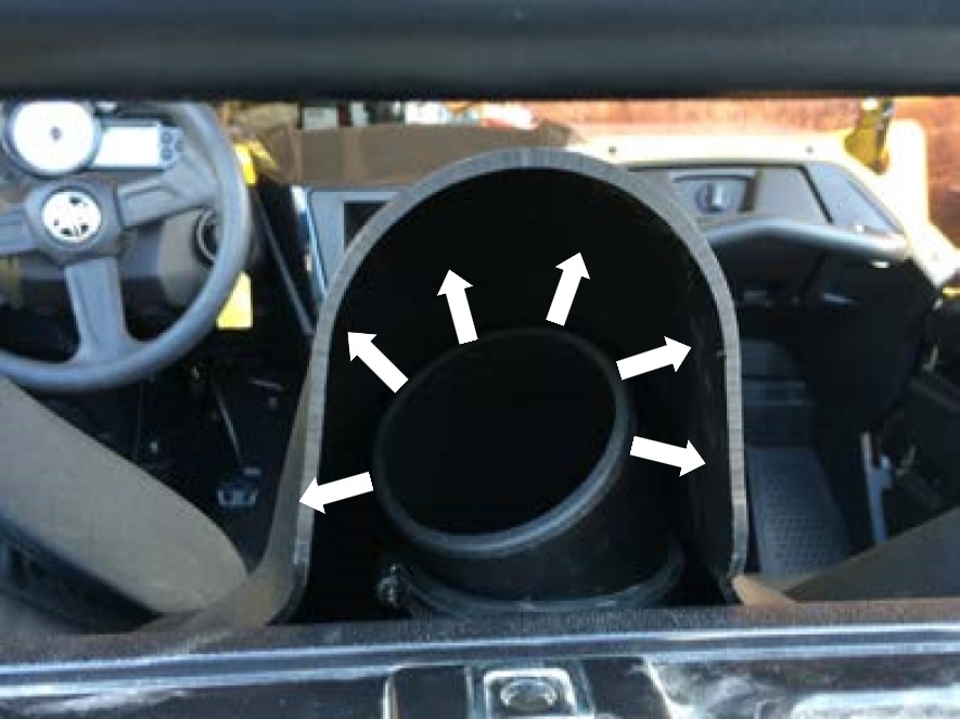
Squeeze down and pull out on the stock air duct to remove it from the stock intake box.
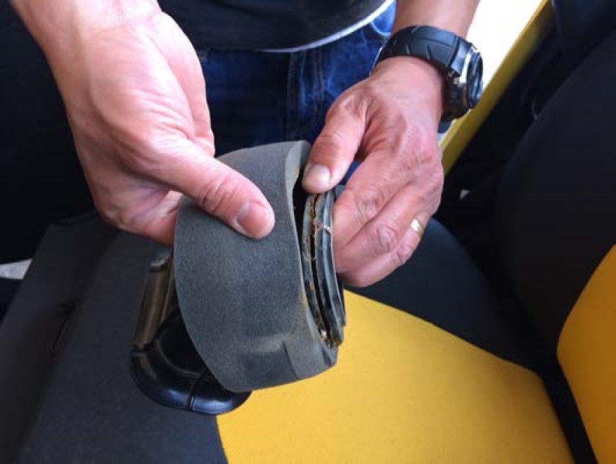
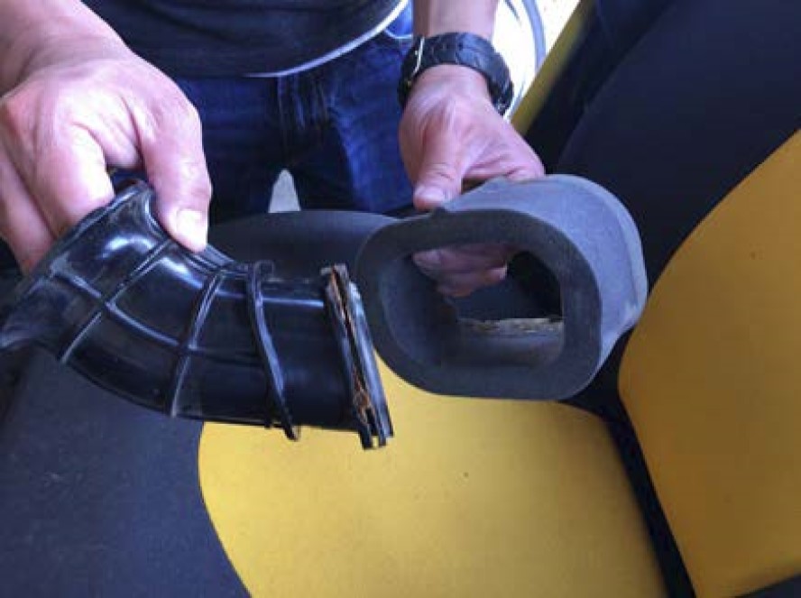
Remove the foam seal from the stock air duct. Pull slowly on the inside around the duct to separate the factory adhesive from the duct. Be careful not to tear the foam.
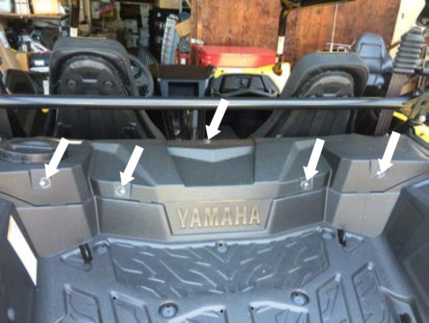
Remove the cargo bed cover by removing the five quick turn fasteners.
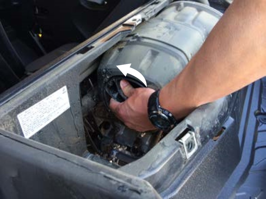
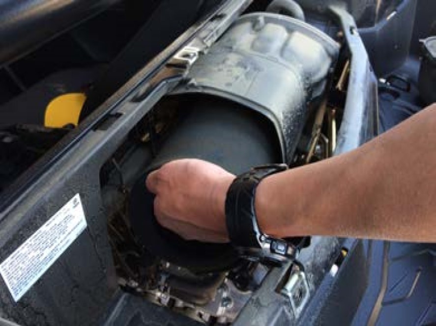
Remove the air cleaner case cap by rotating counter clockwise.
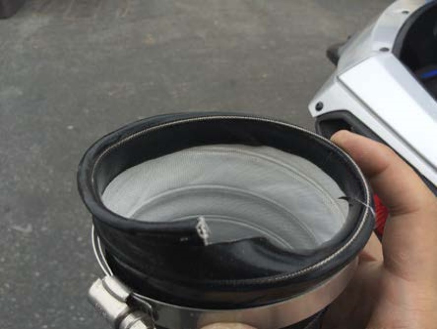
Remove the stock foam air cleaner element.
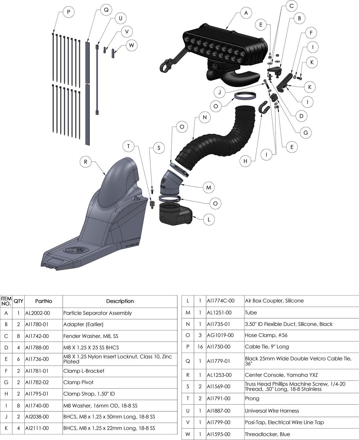
Insert the Coupler (L) into the stock airbox opening. Hook the flange groove onto the airbox opening. You will need to squeeze and push to get the Coupler to sit right on the airbox opening.
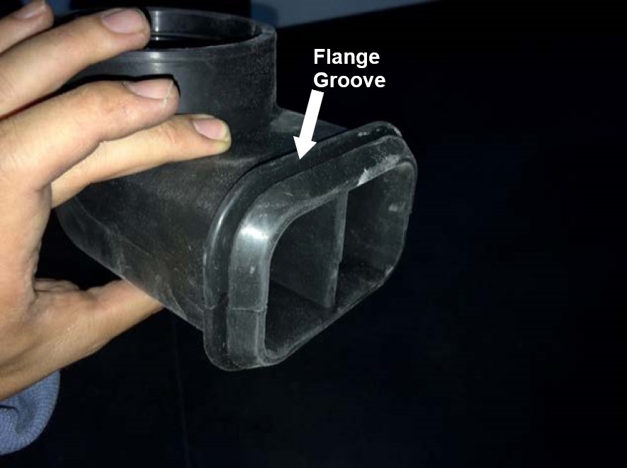
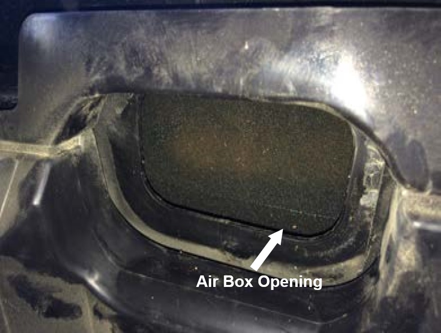
Installing the Coupler (L) will be easier with an extra pair of hands. Someone from the front can push while the person by the stock intake box can guide the flange groove into the air box opening. Once the coupler is in position straighten out of the flanges so that the flange groove fits nicely and seals around the entire opening of the airbox.
Reinstall the stock foam air cleaner element.
Reinstall the air cleaner case cap by rotating clockwise.
Reinstall the cargo bed cover and five quick turn fasteners.
Insert the foam seal removed in Step 5 into the gap around the Coupler (L).
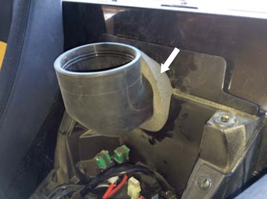
Insert the Air Tube (M) and Hose Clamp #56 (O) into the Coupler (L). The edge of the part number should be facing straight ahead towards the front of the vehicle.
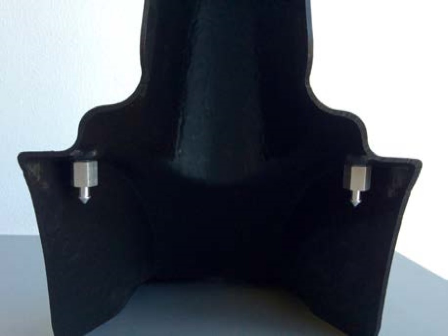
Install the Screw (S) and Prong (T) onto the Center Console (R) with a screwdriver and wrench. The screw should be tightened from the top into the prong. Use the supplied Threadlocker (W) on these threads.
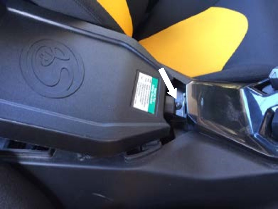
Install the Center Console (R) to check clearance for the Air Tube (M). Insert the center console tab into the shifter cover first and then push down on the center console to get the prongs into the grommets. Make sure that the Air Tube is not hitting the sides and there is enough clearance for the Duct (N). Once everything checks out, remove and set aside the Center Console. Check again to make sure that the grommets are still in place.
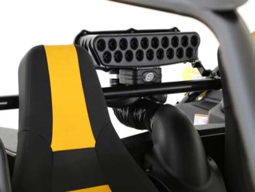
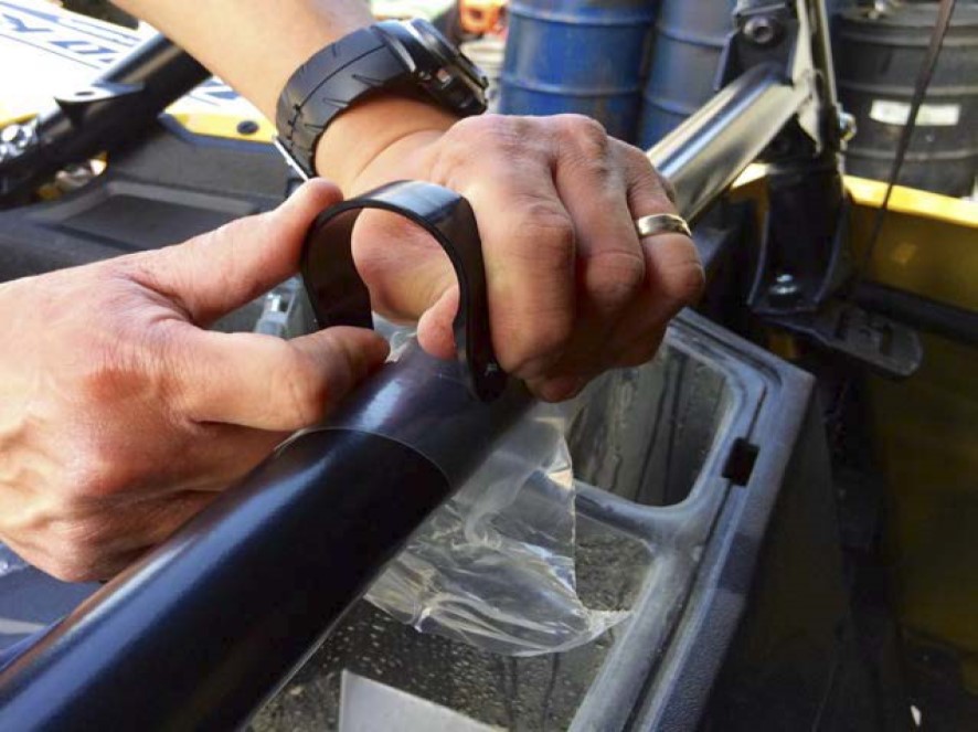
Install the Strap (H) onto the roll cage. Loosely wrapping some plastic around the roll cage will help to slide the strap onto the roll cage easier and prevent scratches.
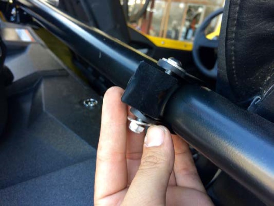
Install the Pivot Body (G) onto the Strap (H) with the supplied Screw (J), Washer (I), Locknut (K) on the roll cage. Do this for both sides. Do not fully tighten the screws and locknuts.
Use a 13mm wrench and 5mm Hex Key to install the Adapter (B) onto the bottom of the Particle Separator (A) with the supplied Screws (D), Washer (C) and Locknuts (E). Tighten these screws and locknuts.
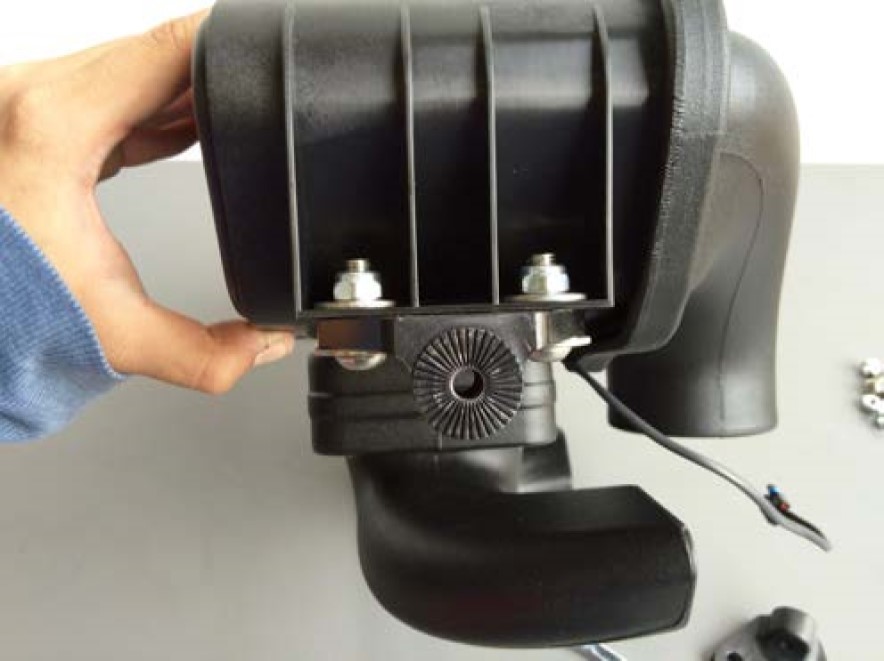
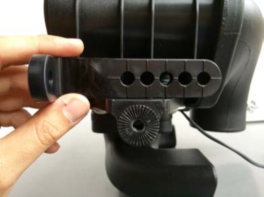
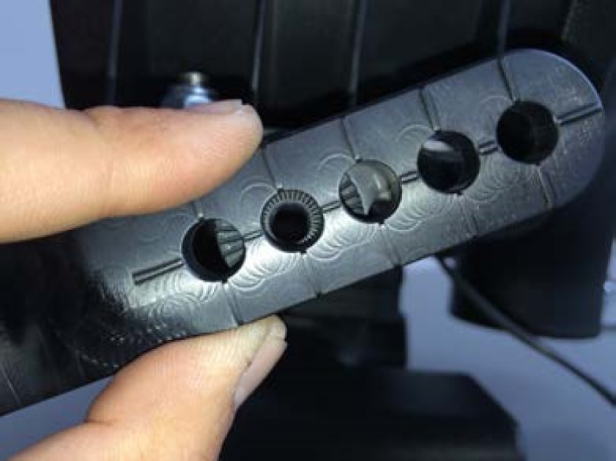
When installing the L Bracket (F), make sure the ribs in the L Bracket are properly seated inside the grooves of the Adapter (B). Any misalignment will damage these parts. Do not attempt to rotate these parts once assembled. They are designed to lock into place once seated. Determine the proper angle to mount the L Bracket to the Adapter based on the desired location for the Particle Separator (A). Make sure the L Bracket is properly seated on the adapter before tightening it in place with the Screw (D) and Washer (C) using a 5mm Hex Key. Do not tighten the hardware if these parts are not seated properly or damage may result. Repeat for the other side of the Particle Separator and make sure the L Bracket on both sides are pointed in the same direction and are aligned with each other.
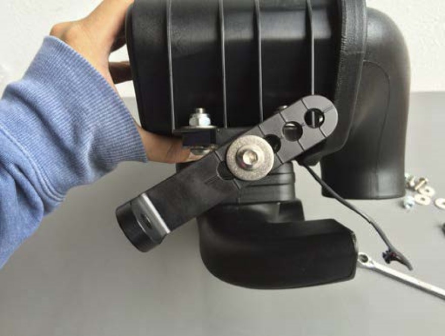
Install the L Bracket (F) onto the Pivot Body (G) using Screw (D) and Washer (C). Use a 5mm Hex Key to tightening the screw. You may have to adjust the position of the Strap (H) and pivot body to get the holes to line up. Do this for both sides. Having an extra pair of hands holding the Particle Separator (A) will make the install easier.
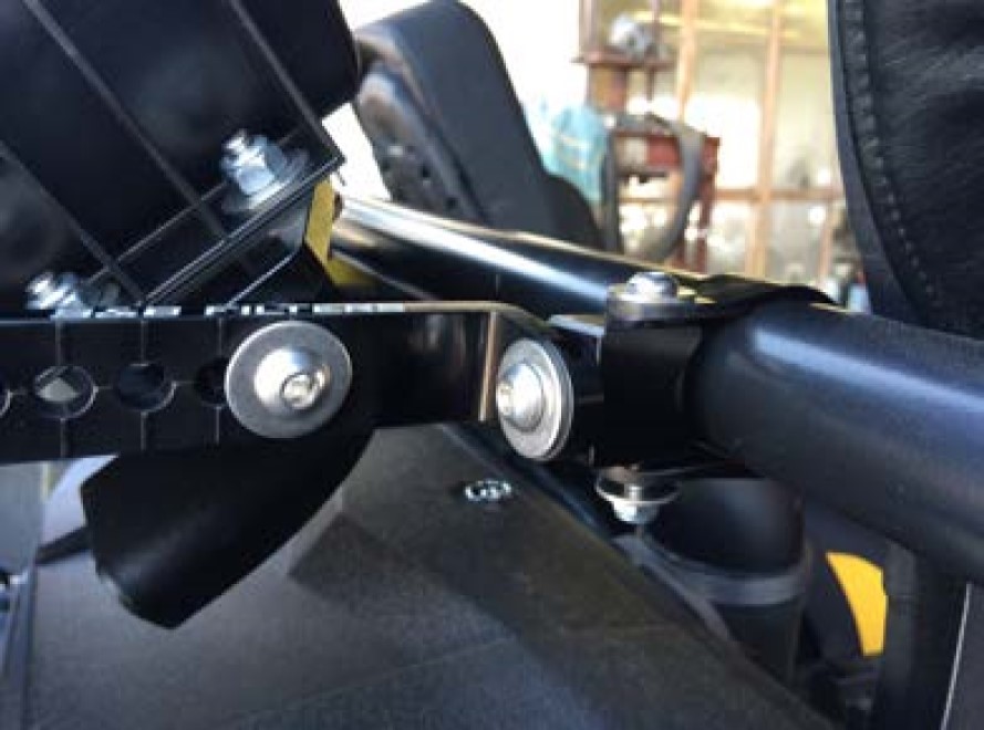
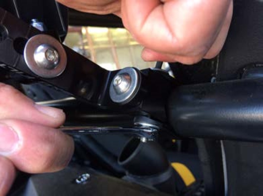
Once you are satisfied with the position, use a 4mm Hex Key and 10mm wrench to tighten the Screw (J), Washer (I), Locknut (K) at the Strap (H). Do this for both sides. Go over all the screws and locknuts again to make sure they are secure and that the Particle Separator (F) is firmly attached to the roll cage.
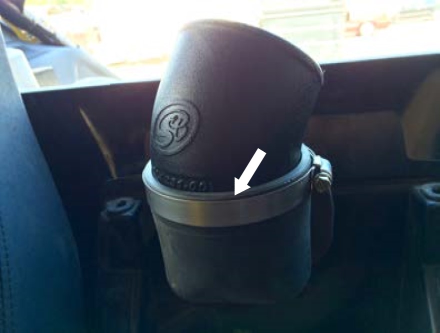
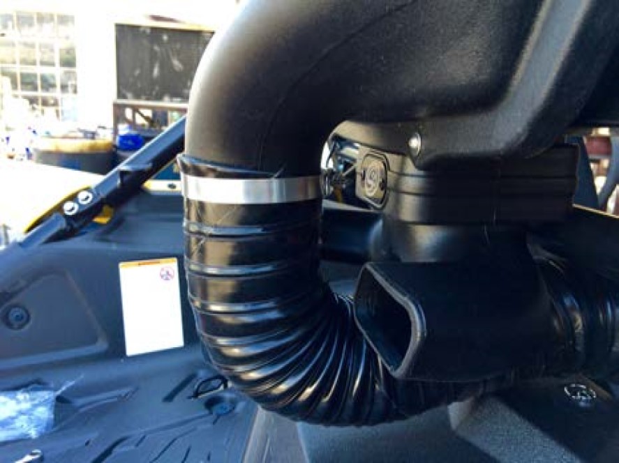
Install Hose Clamp #56 (O) onto the Duct (N).
(Optional) For a cleaner appearance, take the end of the wire and tuck it inside the duct. Do this for both ends of the duct if desired.
Insert one end of the Duct (N) and Hose Clamp (O) onto the Air Tube (M). Tighten the hose clamp at the air tube. Bring the other end towards the opening on the Particle Separator (A). Note the length on the duct you want to cut. We recommend cutting the duct an extra 3" longer so that the ends, along with any wire and strings, can be folded in for a cleaner look.
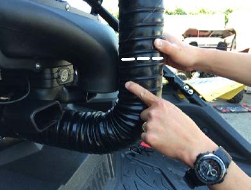
Pierce the Duct (N) centered between the two-wire reinforcements using a razor blade to cut the duct to length. Cut all the way around. Try to cut the duct straight around the center as close as possible.
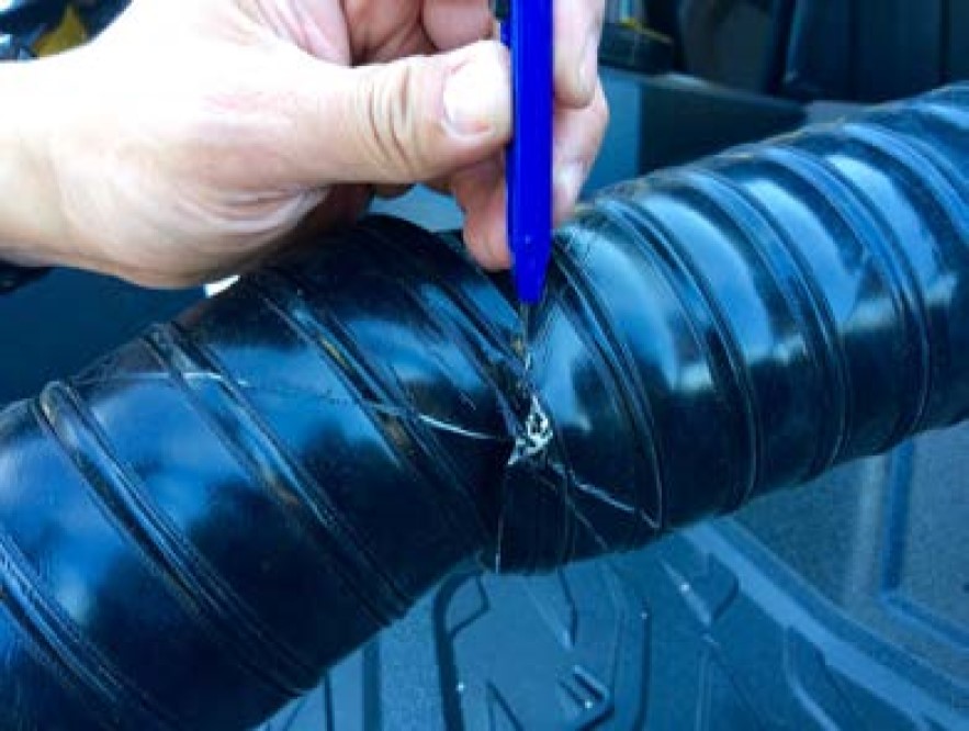
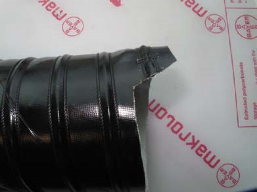
Use scissors to begin the cut. Aim the scissors towards the start of the cut. Do not try to cut through the wire with scissors. Use a mini-bolt or a heavy-duty wire cutter to finish the cutting through the wire and strings.
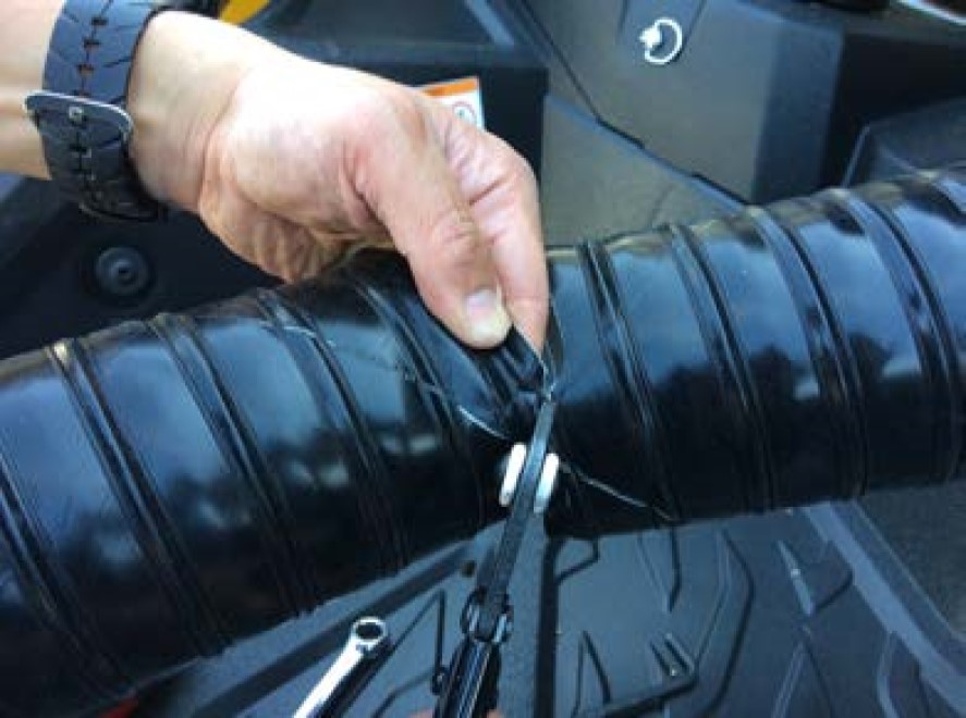
(Optional) Regular staples can be used to secure the ends of the strings to the duct.
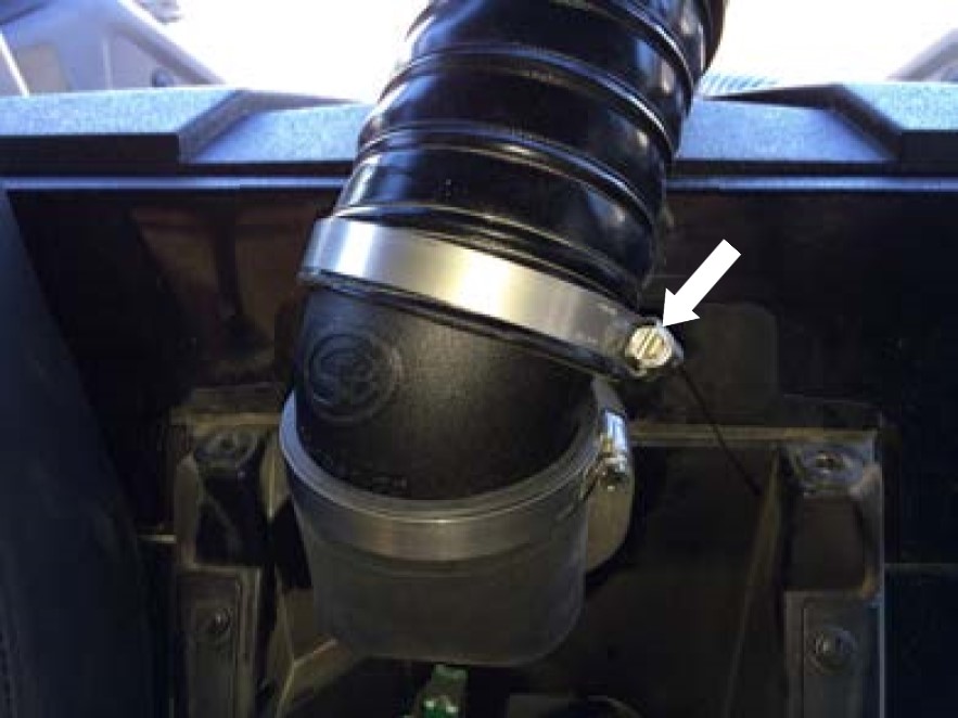
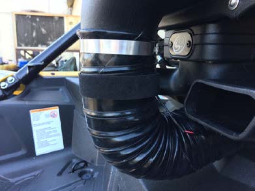
Install the Duct (N) with Hose Clamp #56 (O) onto the plenum of the Particle Separator (A). Tighten the hose clamp with a flat head screwdriver or a 5/16 socket/nut driver
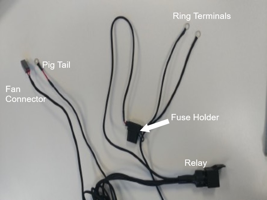
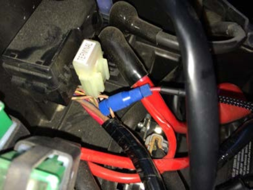
Familiarize yourself with the Wire Harness (U) and each of the connectors. Coming from the relay should be a pigtail, fan connector, and ring terminals. Pig Tail Wire is used in conjunction with the Posi-Tap (V) to tap into a power source. Ring Terminals has the fuse holder with the red and black ring terminals for the battery. Fan Connector has the connector to power the Particle Separator (A).
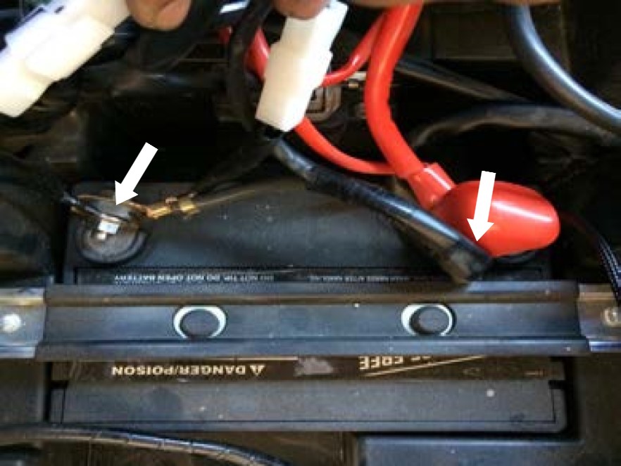
Install the ring terminals onto the battery terminal clamps. Red wire with the fuse holder to (+) and Black wire to (-). Secure the positive terminal first and then secure the negative terminal.
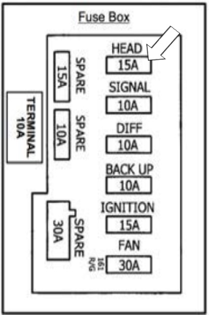
Find the fuse box and look for the brown wire with two green stripes located closest to the passenger side. The wire is connected to the HEAD (15A Fuse).
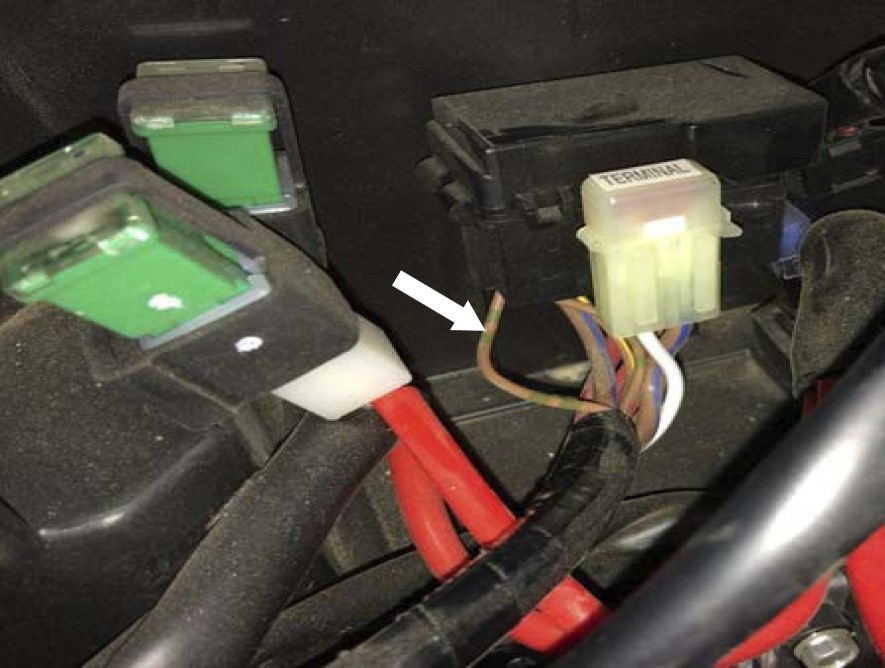
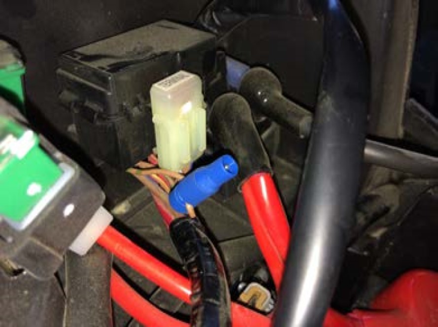
Unscrew the large top cap from the supplied Posi-Tap (V). Place the cap in between the wire.
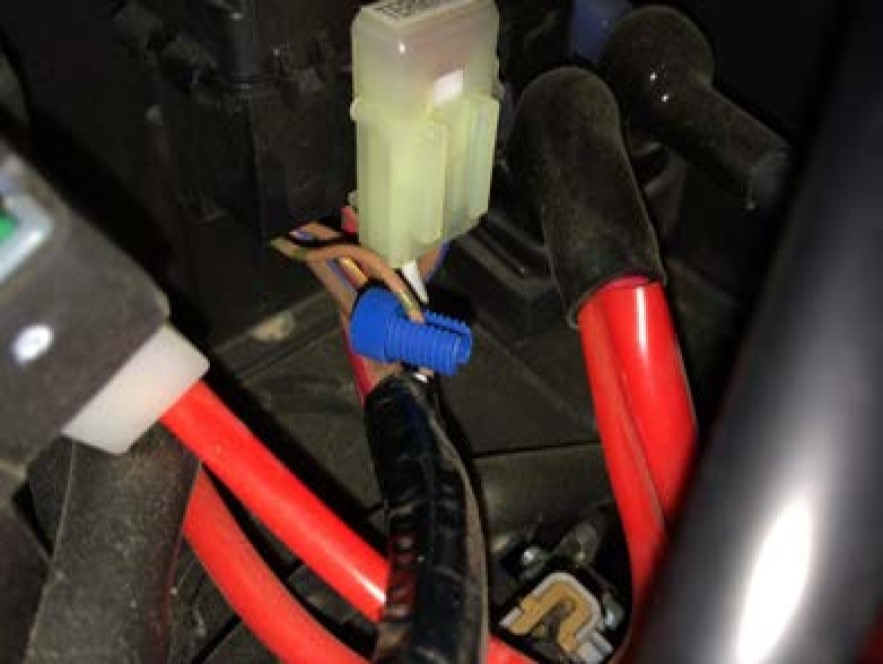
Screw the body around the cap until it is firmly tight.
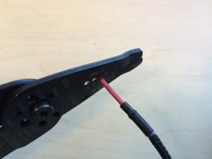
Find the Pig Tail and strip about 3/8” off the end of the wire using a wire stripper.
Unscrew the bottom cap on the Posi-Tap (V) and insert the Pig Tail through it.
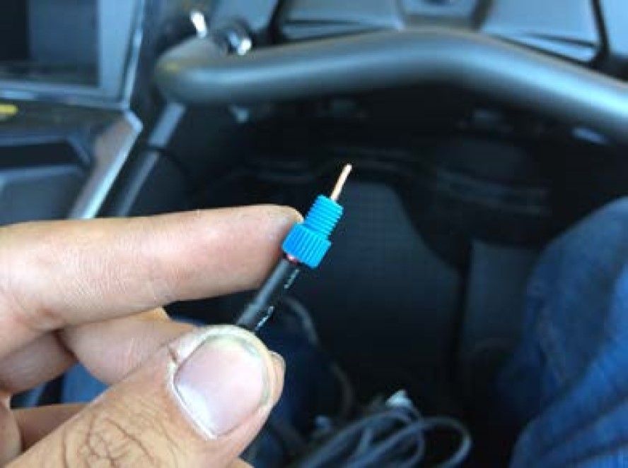
Insert the bottom cap and wire back into the Posi-Tap (V) making sure the strands go around the metalcore. While holding the wire in place, screw the bottom cap back on until it is firmly tight. Double-check both caps to make sure they are tight.
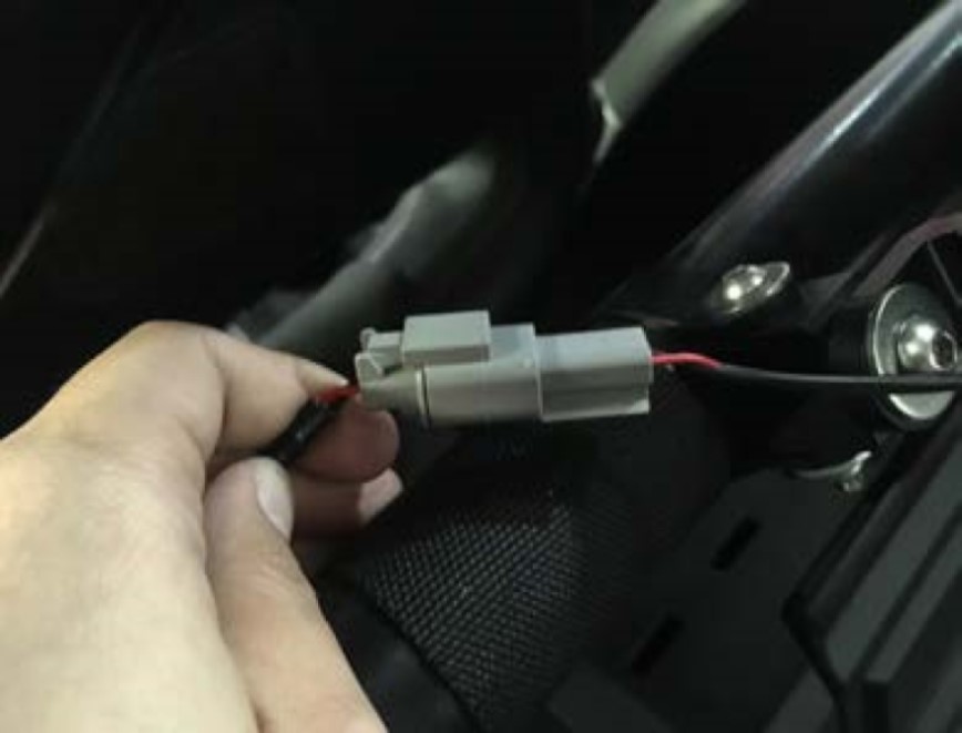
Find Fan Connector and connect it to the Particle Separator (A). Make sure not to cross the connectors. Power to power and ground (black) to ground (black). Note the color of the wires whenever connecting or disconnecting this connector. The connector should snap into each other with very little resistance. Do not try to force the connectors into each other.
Using the supplied Cable Ties (P) or Velcro (Q) to secure the Wire Harness (U) to the Duct (N).
Cable Tie (P) any excess Wire Harness (U) and secure it somewhere under the center console.
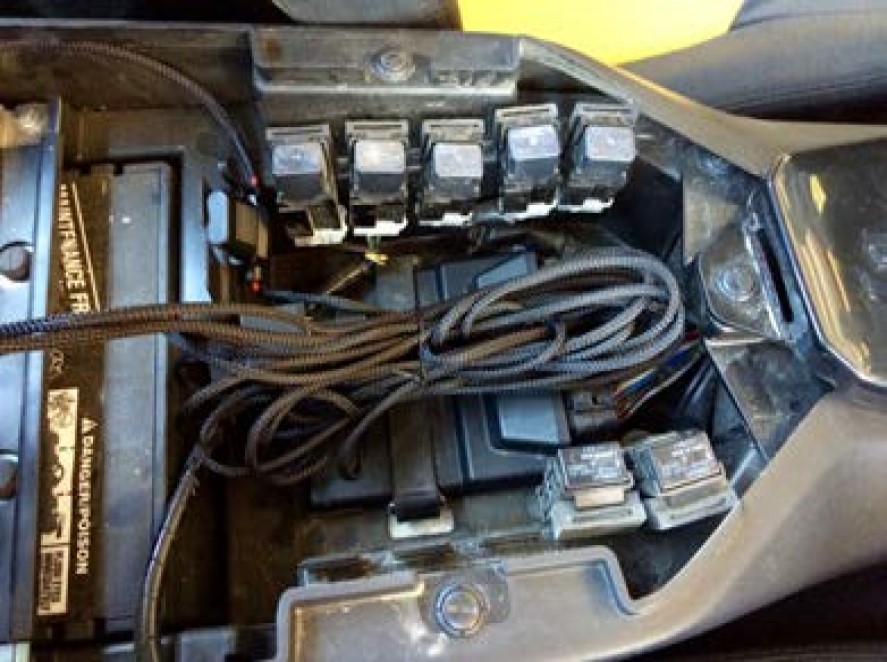
Install the Center Console (R).

Make sure the connectors are all plugged in and secure. Turn the ignition on and make sure air is blowing out the exhaust. If air is not blowing out, double-check your electrical connections. Your installation is now complete.