Install Instructions for 76-2008

Before You Start

• Please read the entire installation manual before proceeding.

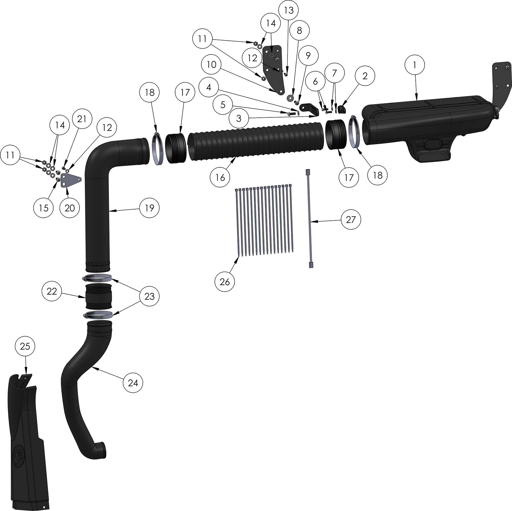
• Ensure all components listed on page 10 are present.

• If you are missing any of the components, call our customer support at (909) 947-0015.

• Do not work on the vehicle while the engine is hot.

• Make sure the engine is turned off, the vehicle is in Park and the Parking Brake is set.

NOTES:

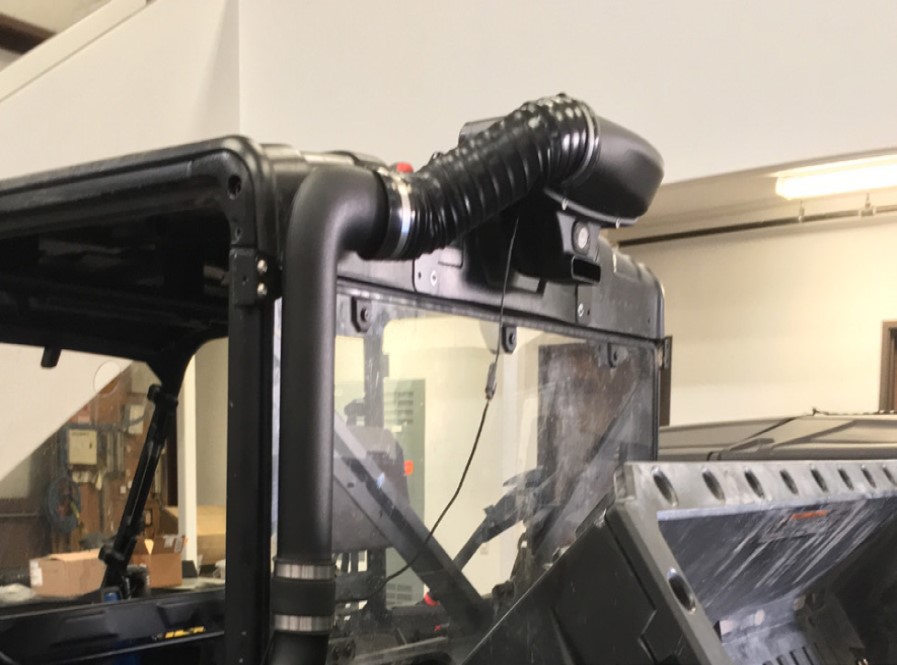
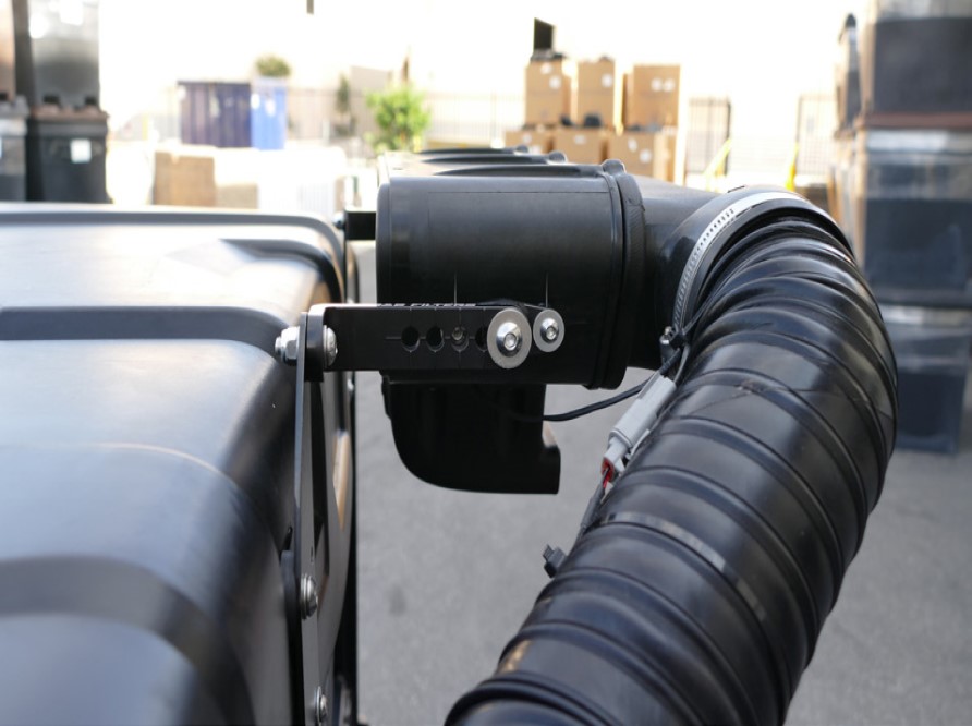
• Kit may not fit with certain Polaris Parts and Accessories. Modification may be required to ensure fit.

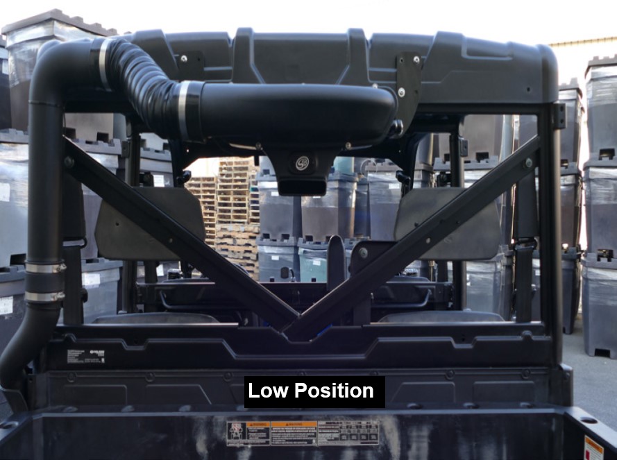
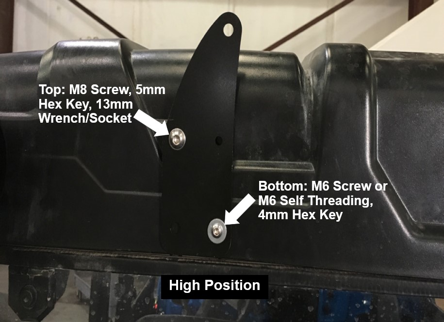
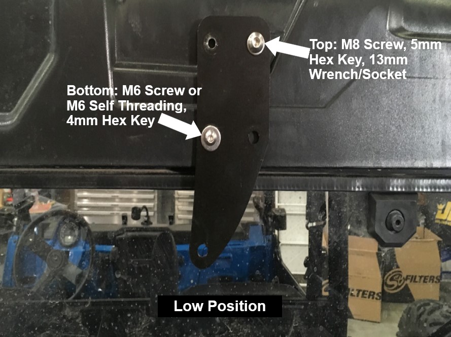
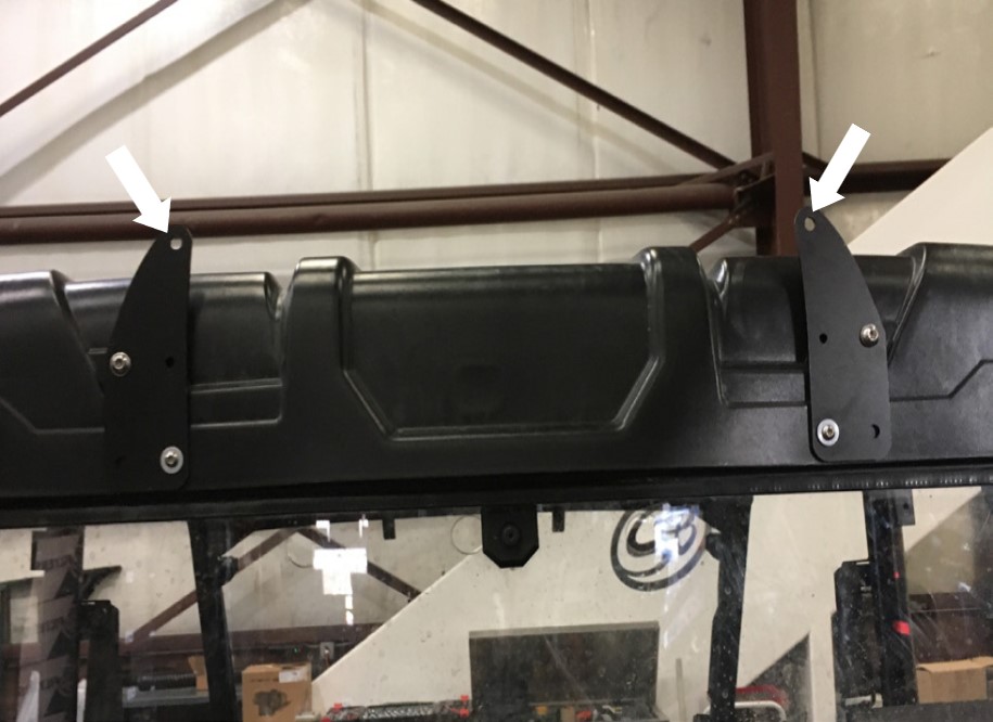
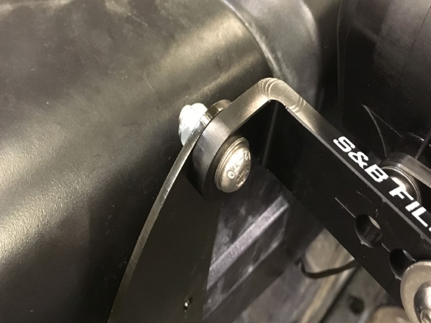
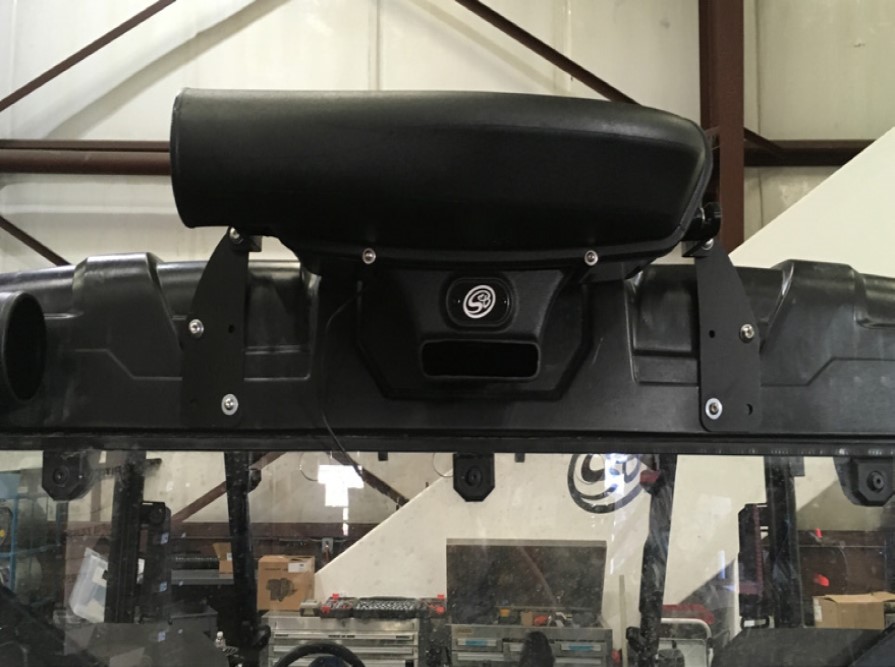
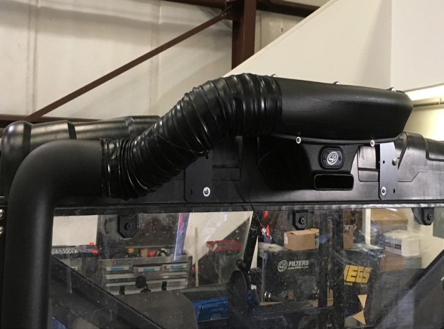
•See Step 15 for installation pictures to determine if your accessories will interfere with the mounting positions. If you want to install the Particle Separator on the lower position with a back window installed, you must purchase the S&F Filters Clamp 100mm Spacer Kit (HP1423-00) or put the separator in the farthest position out on the L-bracket so the Particle Separator can get sufficient airflow.

Required Tools

  • 4mm, 5mm Hex Key
  • 10mm, 13mm Socket/Wrench (*thin 13mm wrench)
  • 5/16” Nut Driver or Flat Blade Screwdriver
  • Drill
  • 5/16” Drill bit
  • T40 Torx
  • Mini-Bolt or Heavy Duty Wire Cutter
  • Razor Blade or Scissor
  • Panel Popper

THREAD LOCKER USE

We have provided a small tube of thread locker in your kit. Whenever you see the symbol above on a step of the instructions, apply 1 small drop of the thread locker to the threads of the screws or bolts. This will keep your hardware from vibrating loose during rough driving. If the hardware ever needs to be removed, do so slowly to avoid having the inserts strip out from the plastic.


STEP 1

Remove the stock side cover on the driver's side. Pull-on the handle to lift the bed up to get more room to work with.


STEP 2A

Remove the three fasteners in front of the side cover. Remove the two top screws and panel clip rivet. If necessary, remove any accessories in the way. Set as de all fasteners removed, they will be reused.


STEP 2B

Remove the two fasteners behind the side cover. Remove the panel clip rivet on top and bottom screw. Set aside only the screw. The panel clip will not be used.


STEP 3

Loosen the hose clamp on the intake duct connected to the side cover.


STEP 4

Lift up and disconnect the side cover from the intake duct, then remove the side cover.


STEP 5

Remove the intake coupler from the stock side cover.


STEP 6

(Optional-Door Hinges installed behind Side Cover) Below you will find a cutout template to help clear your hinges before installing the Replacement Side Cover (T). Line up the sides and bottom then use tape to secure the template then use a cutting tool to cut out a notch.


STEP 7A

Slid the stock coupler onto the Intake Tube #1 (S) and then into the stock intake inlet.


STEP 7B

Do not fully tighten the hose clamp. Adjustments may be needed after the Replacement Side Cover (T) is installed.


STEP 8 💧

Install the Intake Tube Mounting Bracket (P) onto Intake Tube #2 (O) with the M6 Screw (D) and Washer (C). Make sure that the bracket is in the same position as shown below. The bracket should be completely horizontal.


STEP 9

Connect Intake Tube #1 (S) and #2 (O) with the Coupler (Q) and #52 Hose Clamps (R). Leave the hose clamps loose.


STEP 10

Secure Intake Tube #2 (O) onto the roll cage tab with the M8 Screws (L), Washers (N), and Locknuts (M). Tighten both #52 Hose Clamps (R) at the Coupler (Q).


STEP 11

Install the Replacement Side Cover (T). Adjust Intake Tube #1 (S) as needed then tighten the hose clamp on the stock intake inlet from Step 7.


STEP 12A

Install the fasteners removed in Step 2 and secure the Replacement Side Cover (S).


STEP 12B

...Continue from previous step.


STEP 13 💧

Install the Adapter (B) on the mounting bosses of the Particle Separator (A) with the M6 Screws (D) and Washers (C). Tighten these screws. Repeat for the other side.


STEP 14 💧

When installing the L-Bracket make sure that the mounting tab is facing outward as shown below and the ribs in the L-Bracket are properly seated inside the grooves of the adapter. Do not attempt to rotate these parts once assembled. The L-Bracket can only be installed completely horizontal. They are designed to lock into place once seated. Once you’re satisfied with these configurations apply Threadlocker to the M8 Screw (F) and tighten with a Washer (G). Repeat for the other side of the Particle Separator (A) and make sure the L Bracket on both sides are pointed in the same direction and are aligned with each other.


STEP 14 (IMAGE 2) 💧

STEP 15

Determine which position you want to mount the Particle Separator (A). Make sure you have enough clearance to install the Particle Separator Bracket (J) without any interference.

Note: If you want to install the Particle Separator on the lower position with a back window installed, you must purchase the S&F Filters Clamp 100mm Spacer Kit (HP1423-00) or put the separator in the farthest position out on the L-bracket so the Particle Separator can get sufficient airflow.

STEP 15 (IMAGE 2)

STEP 16

For vehicles with Roof Installed Only (skip to Step 17 if this does not apply to you): To install the Particle Separator Bracket (J), we will use four existing holes on the factory roll cage. If you have a factory or aftermarket roof the top holes might be blocked and will need to be drilled out.

Note: Only drill out the two holes. The bottom holes are already tapped.

STEP 16 (IMAGE 2)

STEP 17

At the mounting locations determined in Step 15, install the Particle Separator Mounting Brackets (J) onto the roll cage. The longer side of the mounting bracket must be faced inward. Secure the top hole using the M8 Screws (L), Washers (N), Locknuts (M). Only install the Neoprene Washer (Z) if a roof is installed otherwise leave it out. The neoprene washer goes behind the mounting bracket.

Note: If there is no roof installed, use the M6 Self Threading Screws (K). Otherwise secure with the M6 Screws (Y) and Washers (C). The neoprene washer is not needed without a roof. Repeat for the other side.

STEP 17 (IMAGE 2)

STEP 18

Install the Particle Separator (A) onto the Particle Separator Mount Brackets (J) with the M8 Screws (F), Washers (G), and Locknuts (M).


STEP 18 (IMAGE 2)

STEP 19

Go over all screws and locknuts again to make sure they are secure and that the Particle Separator (A) is firmly secured to the roll cage.


STEP 20

Insert one end of the Flexible Duct (H) onto Intake Tube #2 (O) and bring the other end towards the plenum on the Particle Separator (A). Note the length on the duct you want to cut. We recommend cutting the duct longer so that the ends, along with any wire and strings, can be folded in for a cleaner look.


STEP 21

Pierce the Flexible Duct (H) using a razor, centered between the two-wire reinforcements. Cut all the way around. Try to cut the duct straight around the center as close as possible.


STEP 22

Use scissors to begin the cut. Aim the scissors towards the start of the cut. Do not try to cut through the wire with scissors. Use a mini-bolt or heavy-duty wire cutter to finish cutting through the wire and strings.


STEP 23

(Optional) Install Flexible Duct End Cuff (W) onto both ends of the Flexible Duct (H) with #56 Hose Clamps (I) installed. Do not tighten.


STEP 24

Install the Flexible Duct (H) onto the plenum of the Particle Separator (A) and Intake Tube #2 (O) Tighten all hose clamps. If needed, use Velcro Strap (AA) to secure the duct.


STEP 25

Familiarize yourself with the Wire Harness (V) and each of the connectors. Coming from the relay should be a pigtail, fan connector, and ring terminals. Pig Tail Wire is used in conjunction with the Posi-Tap (AB) to tap into a power source. Ring Terminals have the fuse holder with the red and black ring terminals for the battery. Fan Connector has the connector to power the Particle Separator (A).


STEP 26

Loosen and remove the screw on the negative battery terminal, then disconnect the positive terminal from the battery. Install the Ring Terminals, from the Wire Harness (V), onto the battery terminal clamps. Red wire with the fuse holder to (+) and Black wire to (-) and reinstall the screw. Secure the positive terminal first then the negative terminal.


STEP 27

Route the Wire Harness (V) towards the taillight connector should be routed through the vehicle in such a way that the wire harness is protected from direct contact with flying dirt/rocks and other moving parts on the vehicle. You want to tap into the red wire (signal wire) on the tail light in the next step.


STEP 27 (IMAGE 2)

STEP 28

Unscrew the large top cap and place the cap around the red wire on the taillight connector then screw the body onto the cap until it is firmly tight and pierces the wire.


STEP 28 (IMAGE 2)

STEP 29

The Pig Tail wire comes with a ring terminal that could be connected to a powered terminal bus bar. If you do not have one on your UTV, cut off the terminal and strip about 3/8” of insulation off of the end of the Pig Tail wire. Unscrew the bottom cap on the Posi-Tap (AB) and insert the Pig Tail wire into the main body of the Posi-Tap. Make sure the strands go around the metalcore. While holding the wire in place, screw the bottom cap back on until it is firmly tight. Double-check both caps to make sure they are tight.


STEP 29 (IMAGE 2)

STEP 30

To ensure that you have installed the Wire Harness (V) correctly, connect the Fan Connector to the fan on the Particle Separator (A). Note the color of the wires whenever connecting or disconnecting this connector. Make sure not to cross the connectors. Power (red) to power (red) and ground (black) to ground (black). The connector should snap into each other with very little resistance. Do not try to force the connectors into each other. Turn the key one position clockwise (without bumping the starter) or if you have wired in a switch, flip the switch to the ON position. If you hear the Particle Separator fan turning on, you have wired it correctly. Proceed to the next step.


STEP 30 (IMAGE 2)

STEP 31

Disconnect the connector and finish the wiring. Route the wire as you see fit towards the Particle Separator (A).


STEP 32

Connect the fan connector into the Particle Separator (A). Use Cable Ties (U) or Velcro Strap (AA) to secure the Wire Harness (V).


STEP 33

Group together any excess wires and tie them together with the provided Cable Ties (U). Secure the harness in a place away from any exhaust components or moving parts that could potentially damage the harness.


STEP 34

Double-check to make sure all connectors are plugged in and secured. Turn the ignition on and make sure air is blowing out the exhaust. If the exhaust fan does not turn on, double check your electrical wiring. Your installation is now complete.


Cutout Template