STEP 1
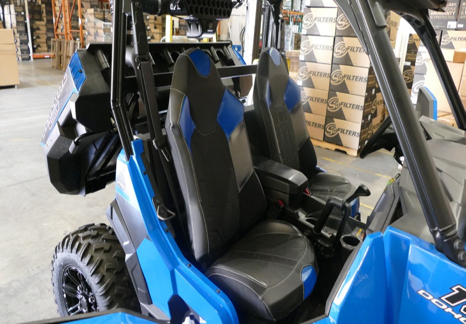
If you have the two-seater variant remove both seats by pulling the latch under the seat and lifting up to reveal the battery compartment. If you have a four-seater variant remove both rear seats.
• Please read the entire installation manual before proceeding.
• Ensure all components listed on page 10 are present.
• If you are missing any of the components, call our customer support at (909) 947-0015.
• Do not work on the vehicle while the engine is hot.
• Make sure the engine is turned off, the vehicle is in Park and the Parking Brake is set.
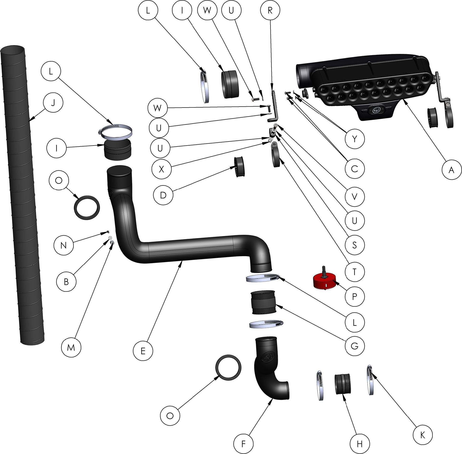
If you have the two-seater variant remove both seats by pulling the latch under the seat and lifting up to reveal the battery compartment. If you have a four-seater variant remove both rear seats.
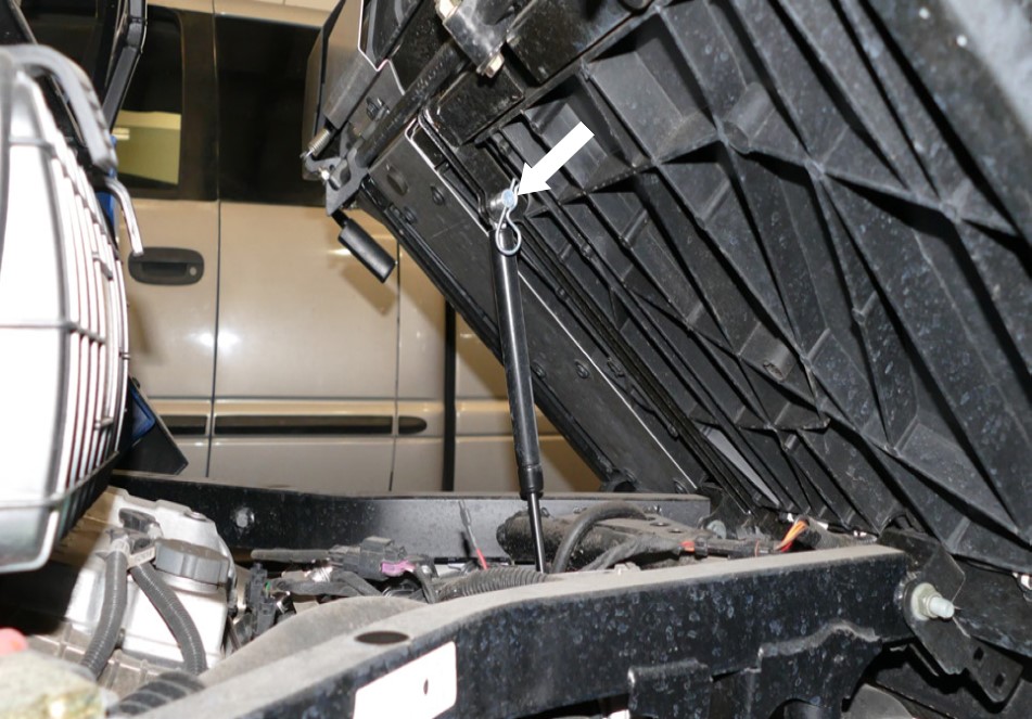
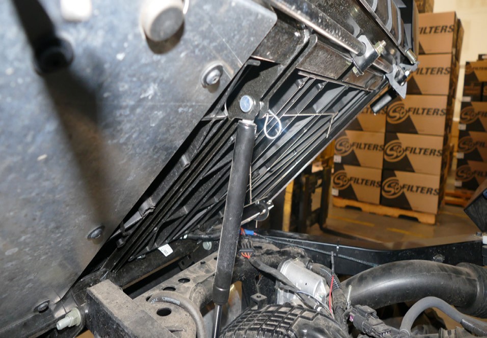
Lift the latch up on the side of the dump bed.
Pull the clip and pin securing the damper to the dump bed so you can extend the dump bed back further to gain more working room.
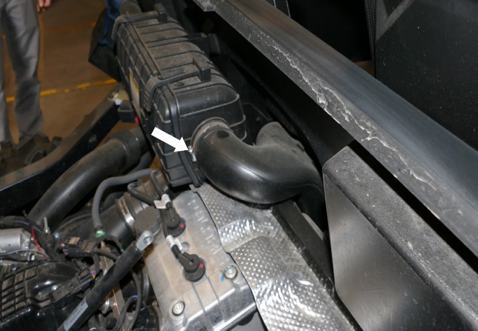
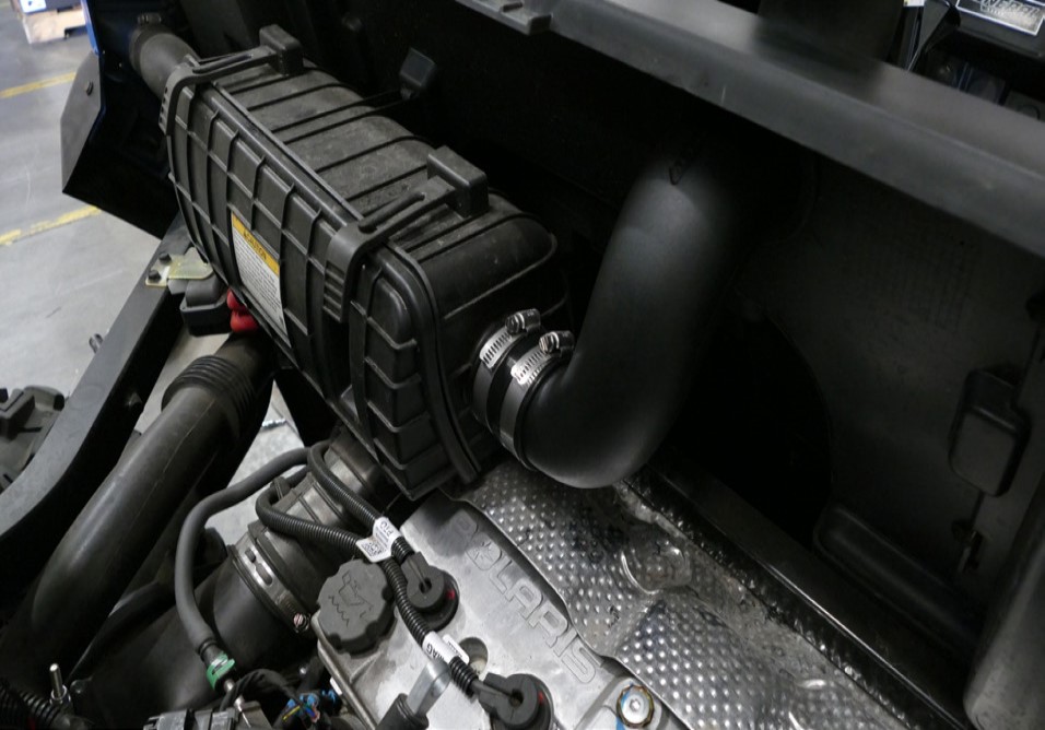
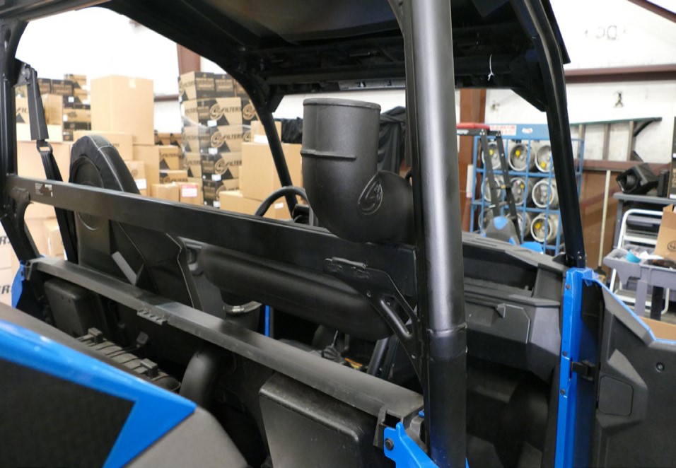
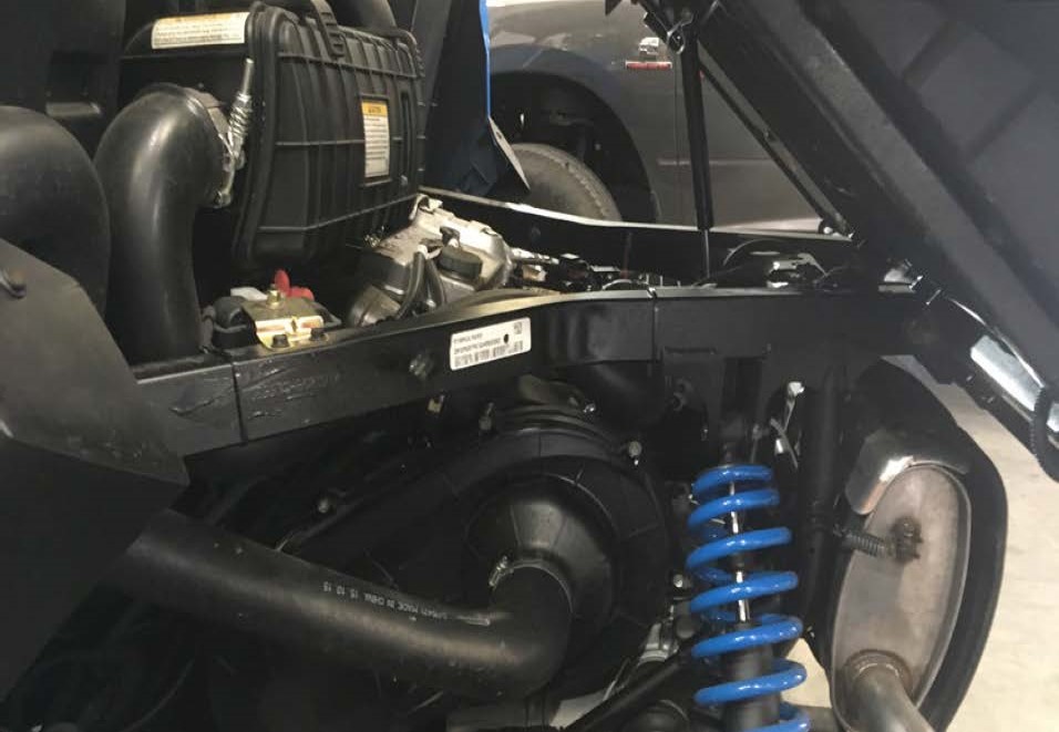
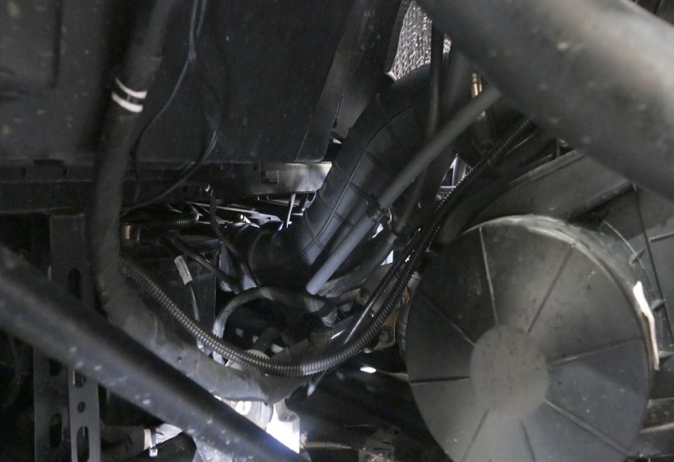
Go to the rear driver side and locate the ducting for the CVT system.
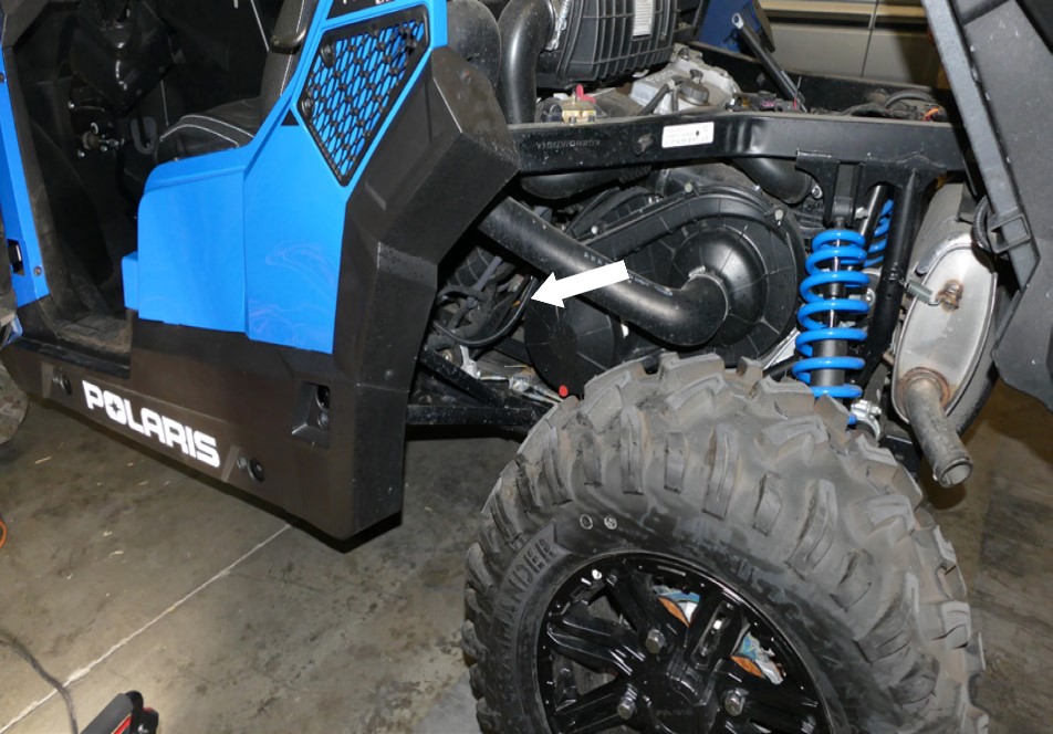
Remove and set aside the CVT ducting from the vehicle so you can have an easier access to the intake ducting. There are two hose clamps you have to loosen. One goes to the front inlet and the other goes to the CVT cover. Using a swivel socket and extensions may help reach the hose clamps easier, as there are limited space.
Tool Required: 6mm, 8mm Socket/Wrench, Swivel Socket, Extensions
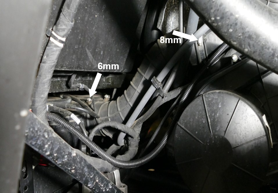
Loosen the hose clamp and pull the intake ducting from the front inlet then disconnect the tubing securing to the intake ducting. Using a swivel socket and extensions may help reach the hose clamps easier, as there are limited space.
Tool Required: 6mm Socket/Wrench, Swivel Socket, Extensions
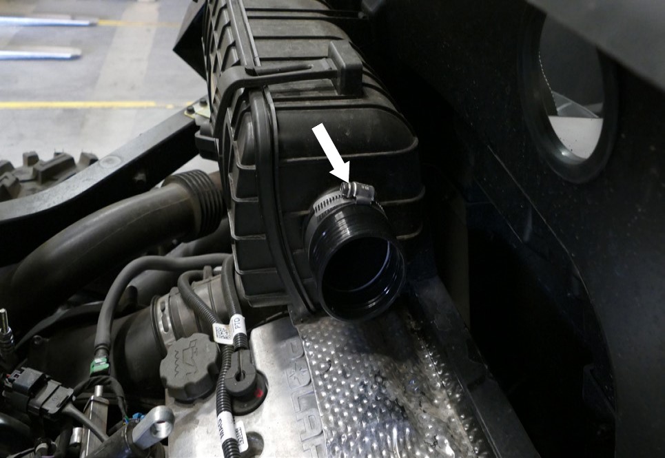
Loosen the hose clamp and pull the intake tube away from the intake box then pull the entire intake assembly out of the vehicle.
Tool Required: 6mm Socket/Wrench
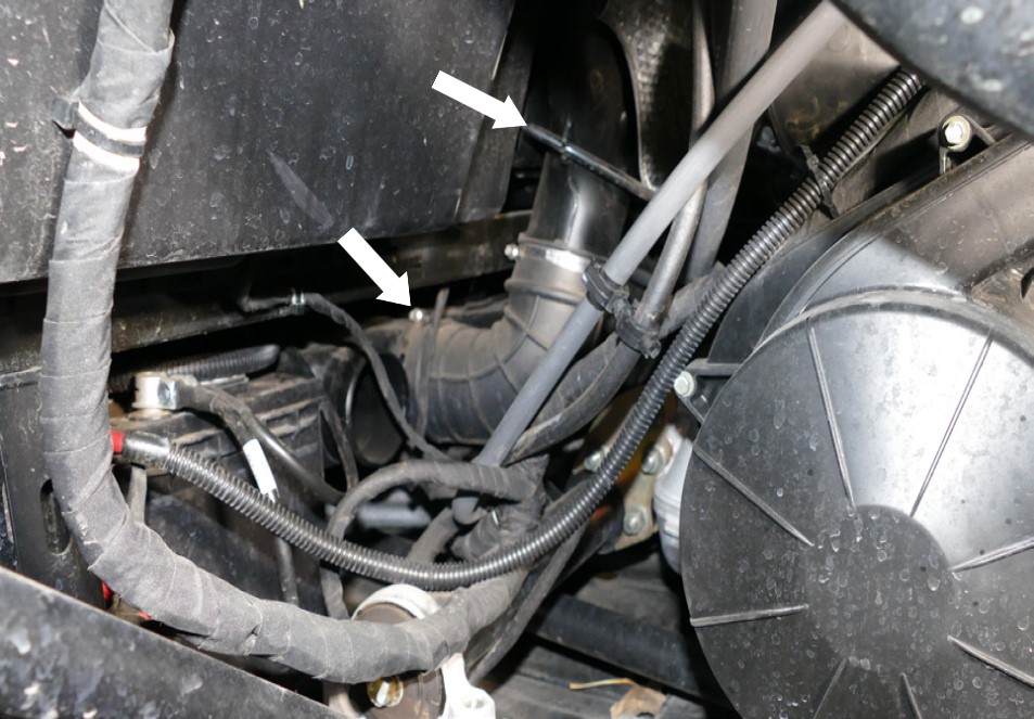
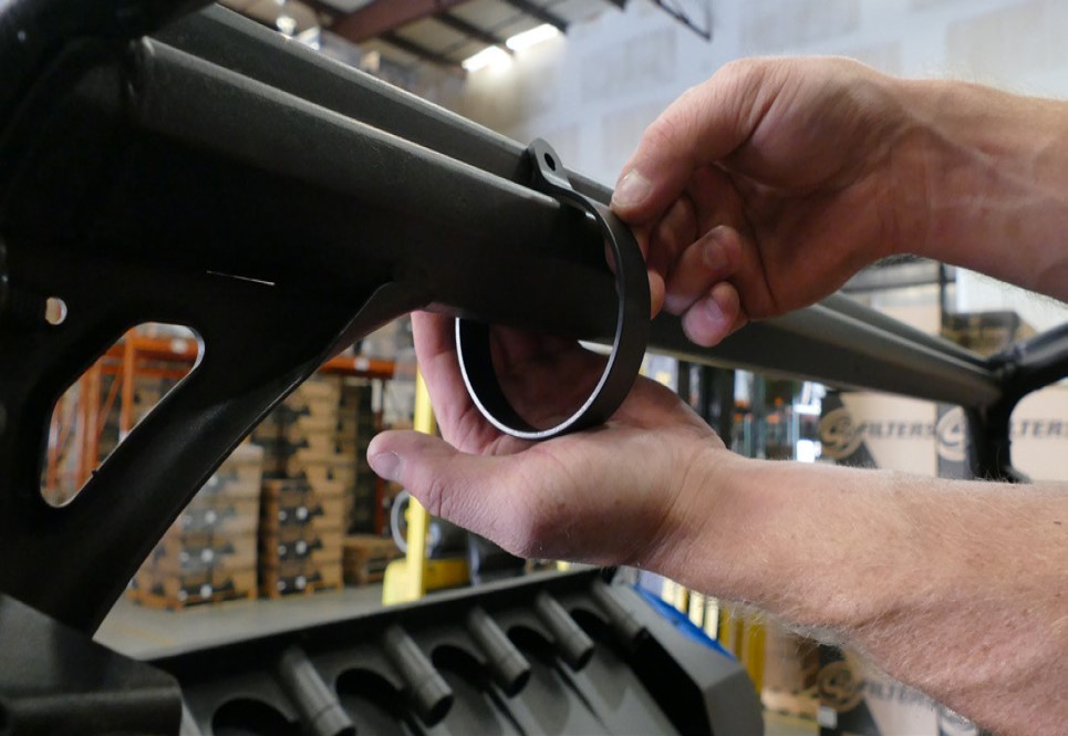
Remove the intake tube seal on the intake box.

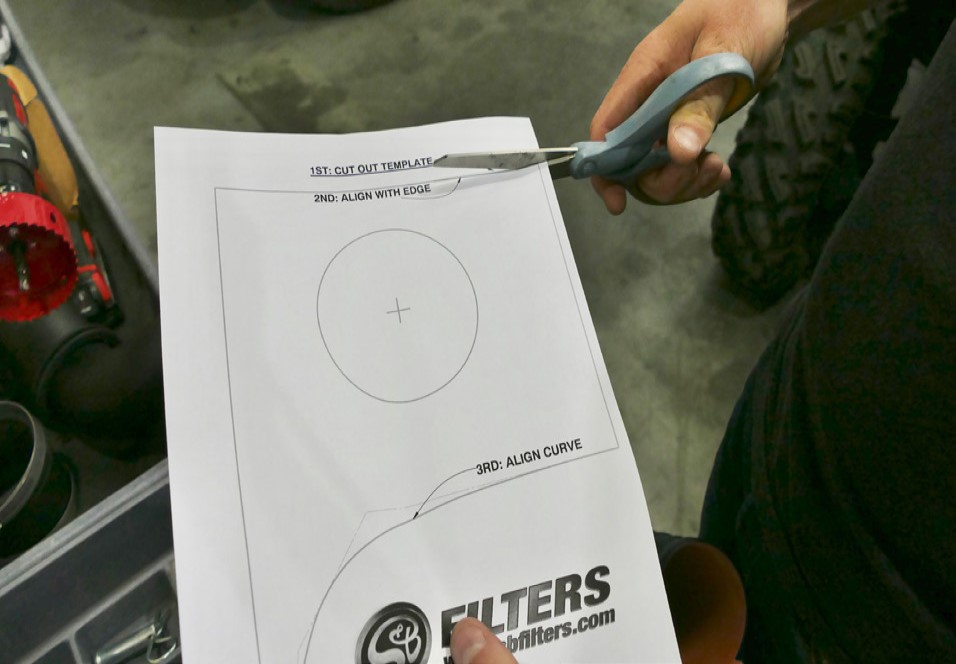
Find the drill template at the end of the instructions and cut out this drill template along the straight edges. This will be used to locate the correct drill location.
Tool Required: Scissor
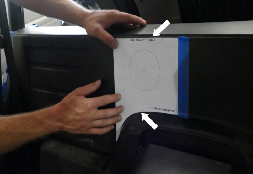
Line up the drill template with the top edge on the back panel and the round edge on the passenger side then use tape to secure the template in place.
Tool Required: Tape
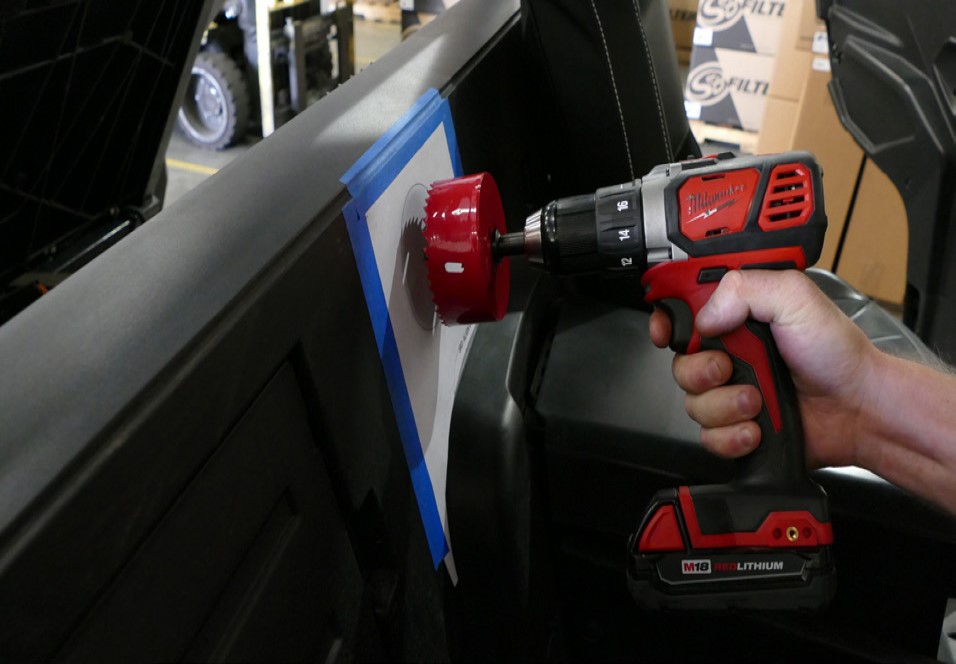
Attach the provided Hole Saw (X) and line up the saw with the template. Read the warning sheet before attempting to use the hole saw. Start slowly and then progressively increase the speed. Doing so should give you a better cut. Try to keep the Hole Saw (X) as leveled as possible to the surface.
Tool Required: Drill, Hole Saw
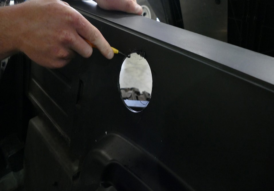
Remove the cutout template and use a knife or deburring tool to clean up the hole as best you can.
Tool Required: Deburring Tool or Razor Blade
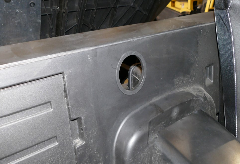
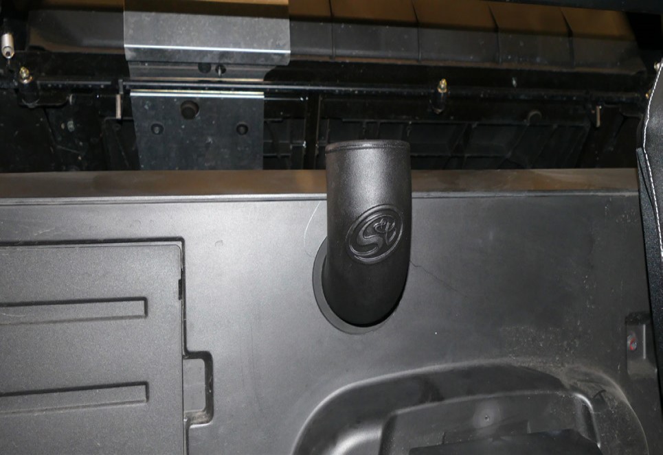
Install the Panel Seal (X) into the back panel.
Install the Coupler (Q) with the two #40 Hose Clamps (T) onto the stock intake box inlet. Tighten only the hose clamp closest to the stock intake box.
Tool Required: 8mm Socket/Wrench
Insert Intake Tube #1 (O) through the back panel and into the Coupler (Q).
Make any adjustments as needed then tighten the other hose clamp. The logo on the Intake Tube #1 (O) should be facing towards the front of the vehicle.
Tool Required: 8mm Socket/Wrench
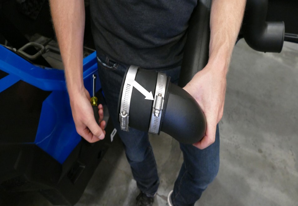
Install the Coupler (P) with the #56 Hose Clamps (U) onto the Intake Tube #2 (N). The coupler is to be installed onto the end with the short bend without the S&B logo on the side of the tube. Tighten the hose clamp on the intake tube only.
Tool Required: 8mm Socket/Wrench
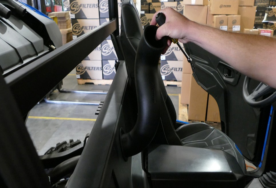
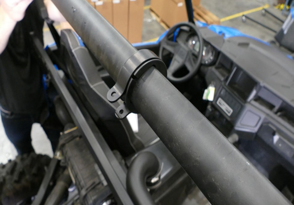
Connect Intake Tube #2 (N) with Intake Tube #1 (O). Do not tighten the hose clamp yet. If you have a back window installed, we provided an additional Panel Seal (X) that you can feed the intake tube #1 through.
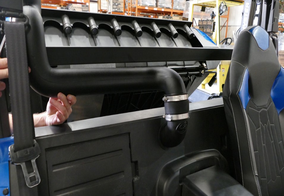
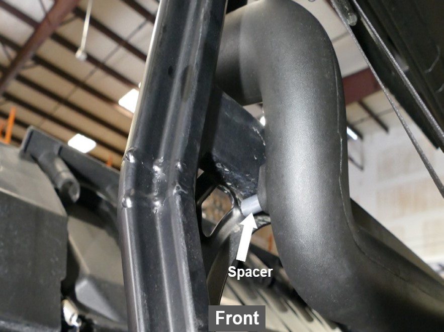
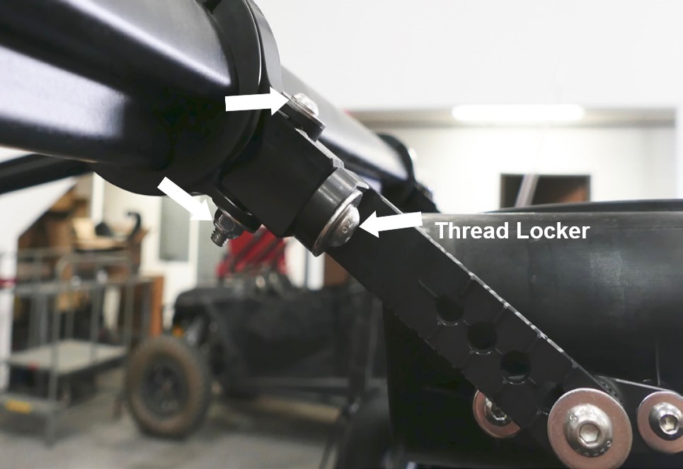
Install the Spacer (V) to secure Intake Tube #2 (N) with the M4 Screw (W) and Washer (B). Apply a small amount of Thread Locker (AD) on the M4 Screw before tightening. The spacer should be installed in front of the insert on intake tube #2 in front of the middle rectangular bar and the screw through the back of the middle rectangular bar. Tighten the #56 Hose Clamp (U) at the coupler connecting with intake tubes.
Tool Required: 2.5mm Hex Key, 8mm Socket/Wrench
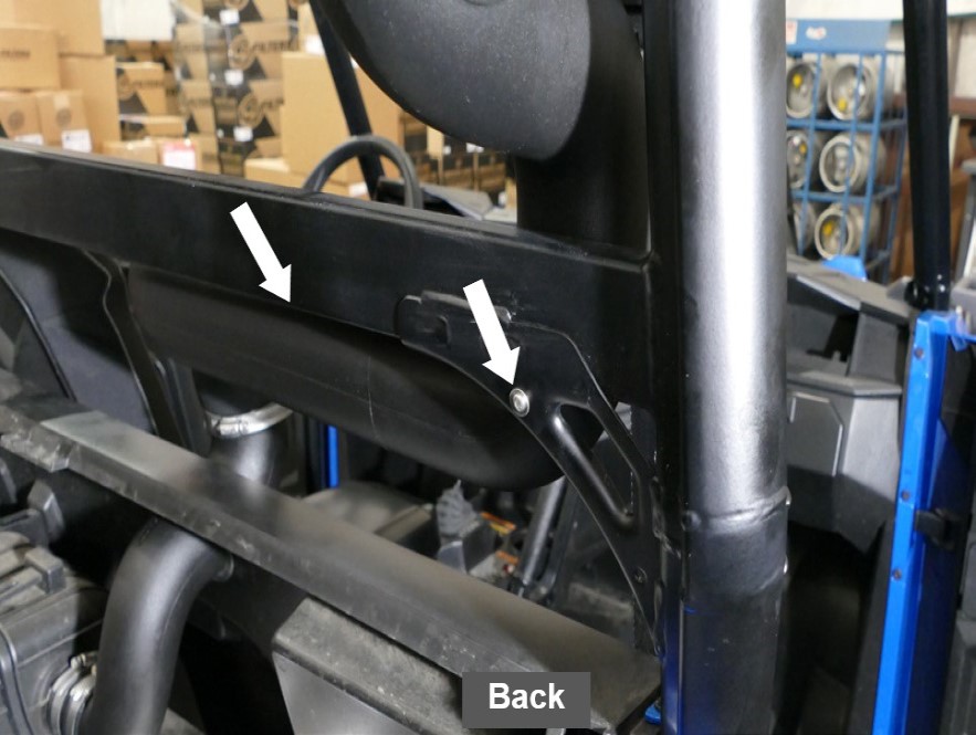
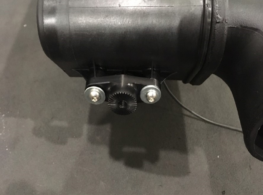
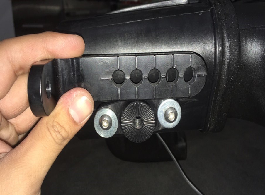
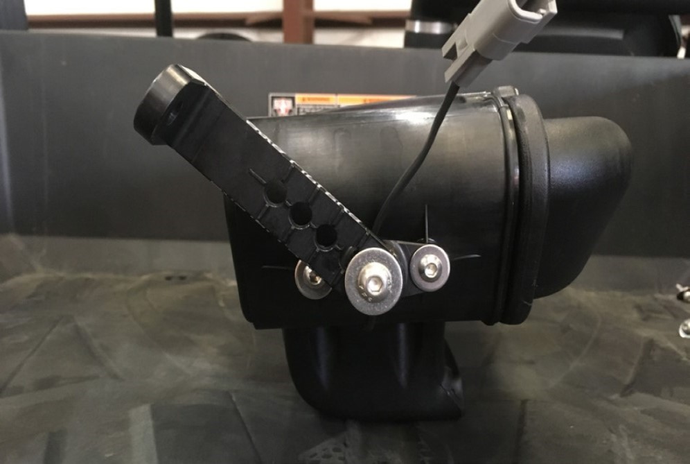
(Optional) On the Particle Separator Assembly (A) press the wiring harness from the fan into the tabs underneath to secure the wires more tightly.
Install the Adapter (L) on the mounting bosses of the Particle Separator (A) with the M6 Screws (C) and Washers (D). Apply a small amount of Thread Locker (AD) on the M6Screw before tightening. Repeat for the other side.
Tool Required: 4mm Hex Key
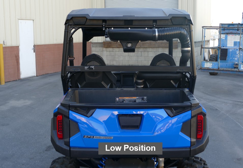
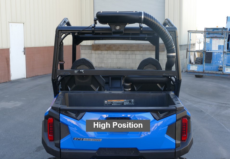
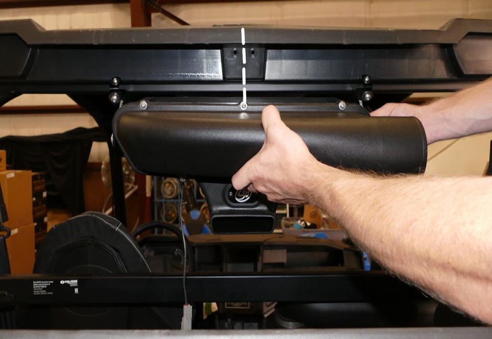
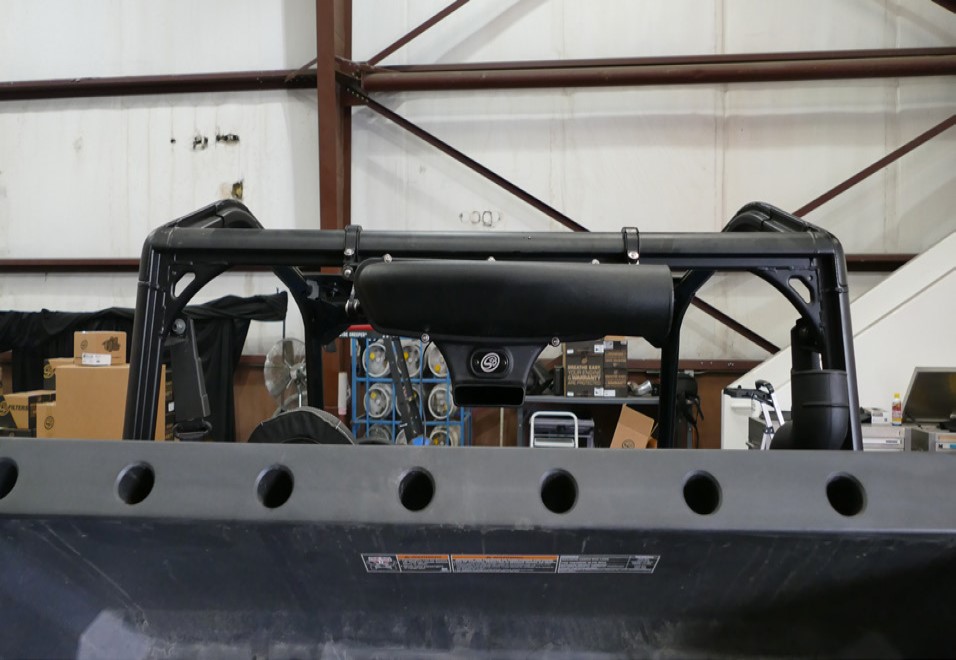
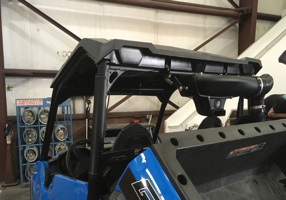
Determine which position you want to mount the Particle Separator (A).
Note: If you want to install the Particle Separator on the high position with a stock roof installed, you must purchase the S&B Filters Clamp 100mm Spacer Kit (HP1423-00) or will need to make an additional modification to the roof to get the particle separator mounted.
Determine the proper angle to mount the L Bracket to the Adapter based on the desired location for the Particle Separator (A). When installing the L Bracket (K), make sure the ribs in the L Bracket are properly seated inside the grooves of the Adapter (L). Do not attempt to rotate these parts once assembled. They are designed to lock into place once seated. Once you’re satisfied with these configurations apply a small amount of Thread Locker (AD) to the Screw (F) then tighten with the Washer (E). Repeat for the other side of the Particle Separator and make sure the L Bracket on both sides are pointed in the same direction and are aligned with each other.
Tool Required: 5mm Hex Key
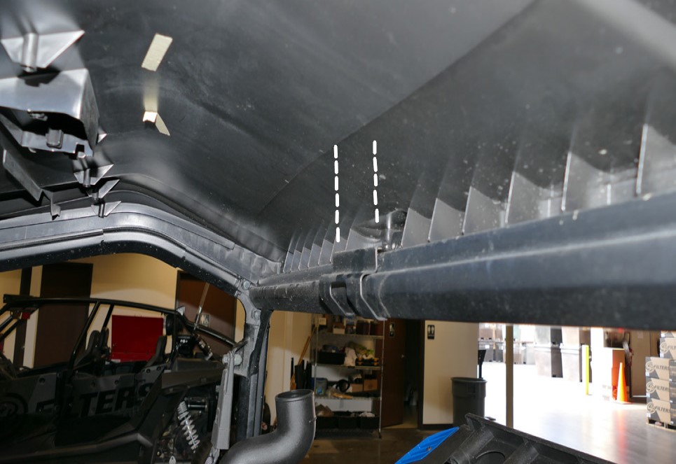
(Optional Step 21- 22) If you have the stock roof installed on your vehicle. Follow the next steps to see how the roof is removed and where modification is needed to install the Particle Separator Assembly (A) with the roof installed. If you do not have the stock roof installed please move onto Step 23. Position the particle separator at its mounting location and at the end of the L-Bracket (K) add modification marks so you know where the cuts will be needed. The width of the gap should be no more than 1.75”.
Tool Required: Permanent Marker
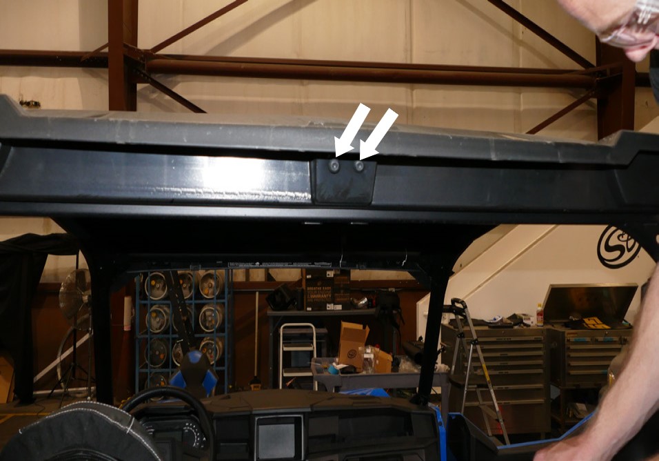
(Optional) To remove the stock roof there are two mounting screws in the back by the dump bed and four mounting screws that can be accessed through the cab.
Tool Required: T40 Torx
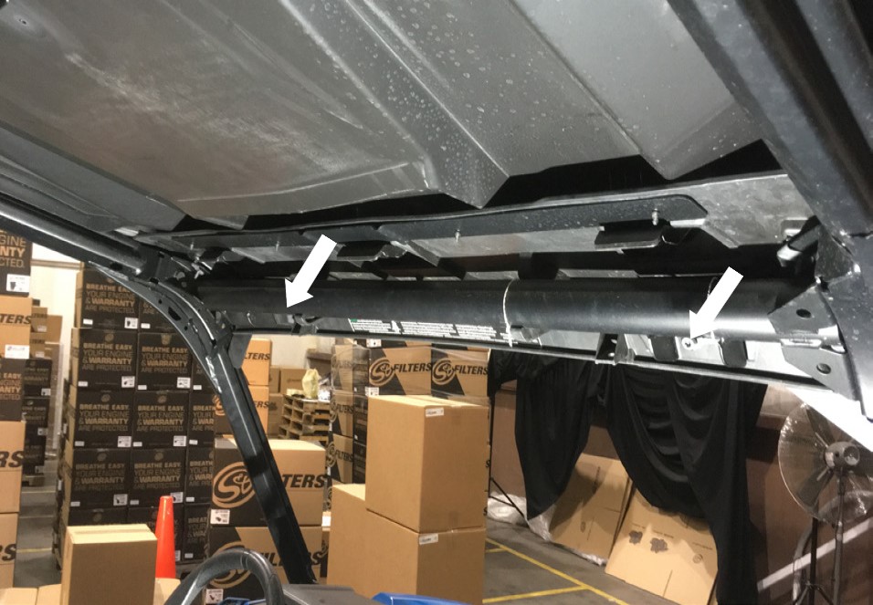
(Optional) Remove the mounting bracket from inside the cab where the two rear mounting screws were located.
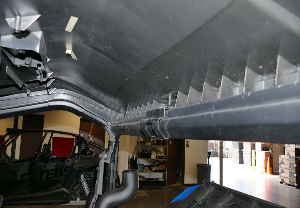
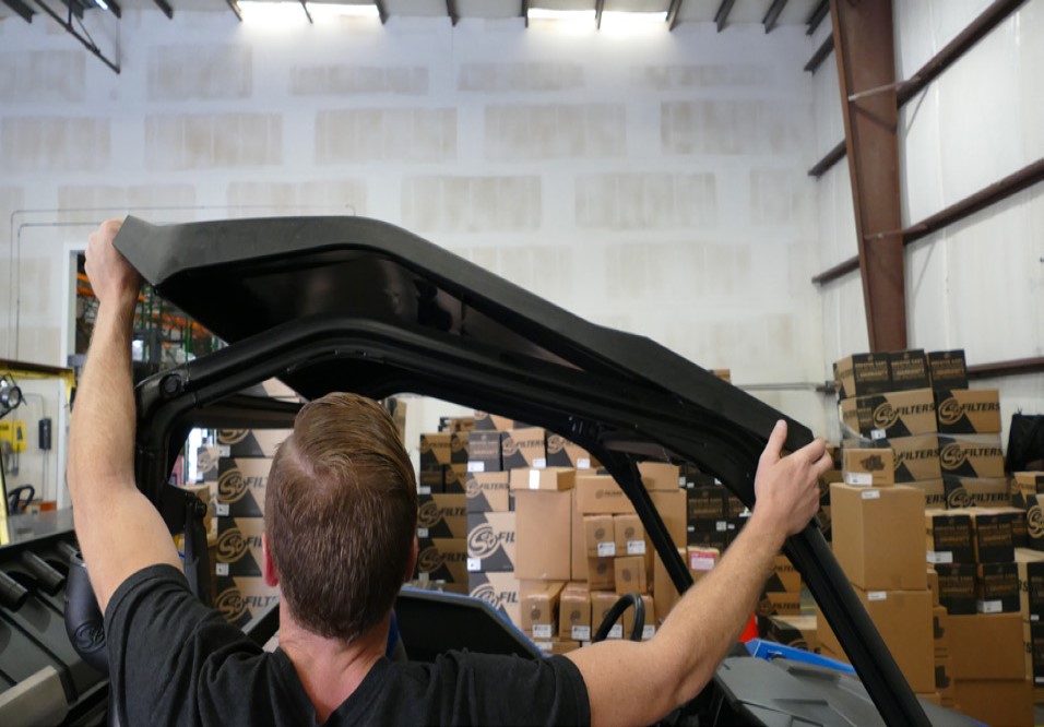
(Optional) Push the stock roof forward first to get the tabs out of the slots on the lower roof piece then lift up to remove the roof from the vehicle.
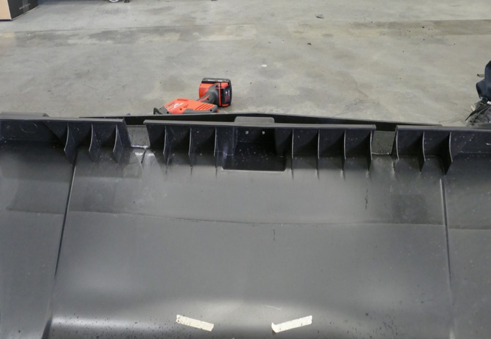
(Optional) Carefully cut the roof at the marks made in Step 21. Clean up the edges of the cut.
Tool Required: Hack Saw, Razor Blade
Install the two Straps (J) onto the roll cage. Do not pull the ends of the straps open. Push the straps onto the roll cage until they snap into place.
Align and press the two sets of Roll Bar Adapter (M) together onto the roll cage.
Note: there will be a slight gap between the roll bar adapters.
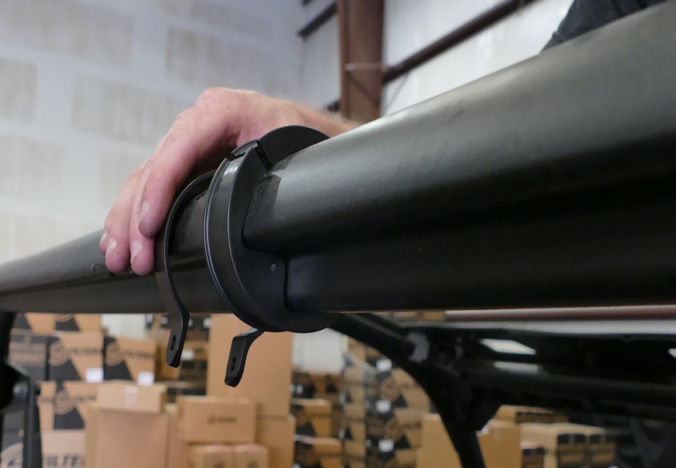
Slide the two Straps (J) over the Roll Bar Adapter (M).
Install the Pivot Body (I) onto the Strap (J) with the supplied M6 Screw (G), Locknut (H), and Washer (D) on the roll cage. Do not fully tighten the screws and locknuts. Leave the strap loose. Repeat for both clamps.
Tool Required: 4mm Hex Key, 10mm Socket/Wrench
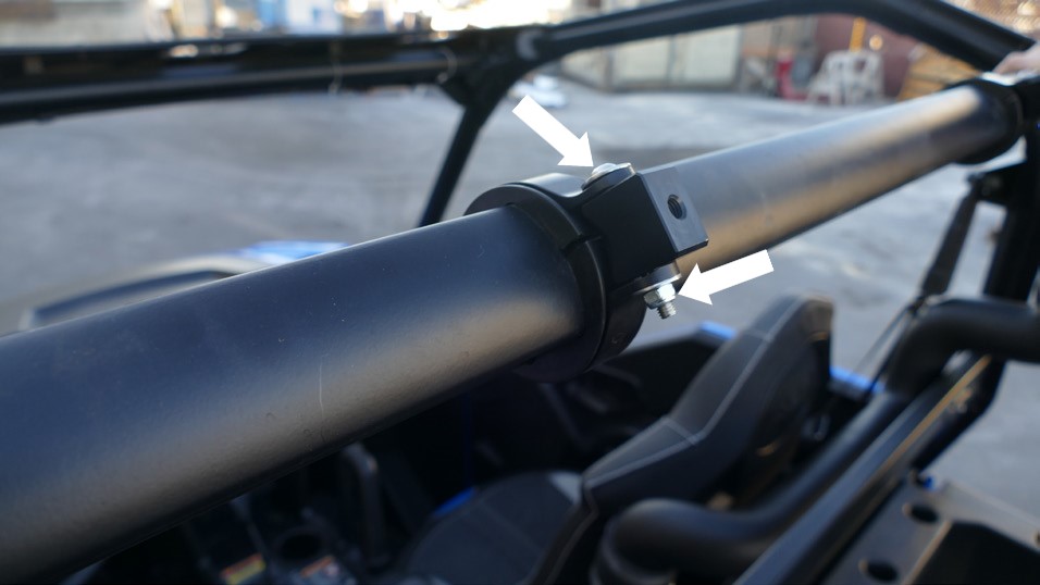
Install the L Bracket (K) onto the Pivot Body (I) using M8 Screw (F) and Washer (E). Apply a small amount of Thread Locker (AD) to the screw before installing. You may have to adjust the position of the Strap (J) and pivot body to get the holes to line up. Do this for both sides. Having an extra pair of hands holding the Particle Separator Assembly (A) to help line up the holes will make the install easier. Tighten all screws and nuts.
Tool Required: 4mm Hex Key, 5mm Hex Key, 10mm Socket/Wrench
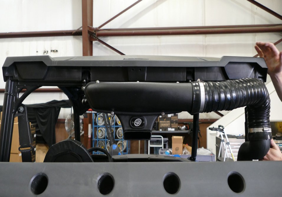
Double-check that all screws and locknuts are tight and that they are securely holding the Particle Separator Assembly (A) assembly to the roll cage.
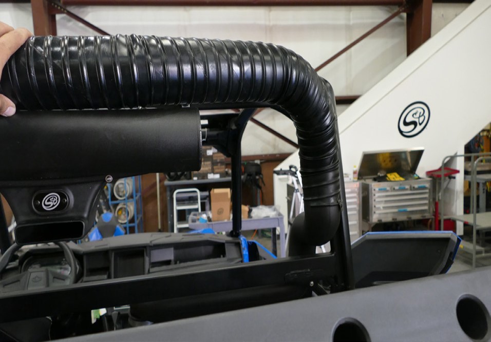
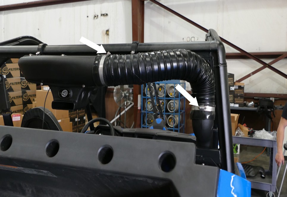
Insert one end of the Flex Duct (S) onto the Intake Tube #2 (N), do not tighten. Bring the other end towards the plenum on the Particle Separator Assembly (A). Note the length needed to reach the clean air plenum on the Particle Separator. We recommend adding an extra 3” more to the length of the duct needed.
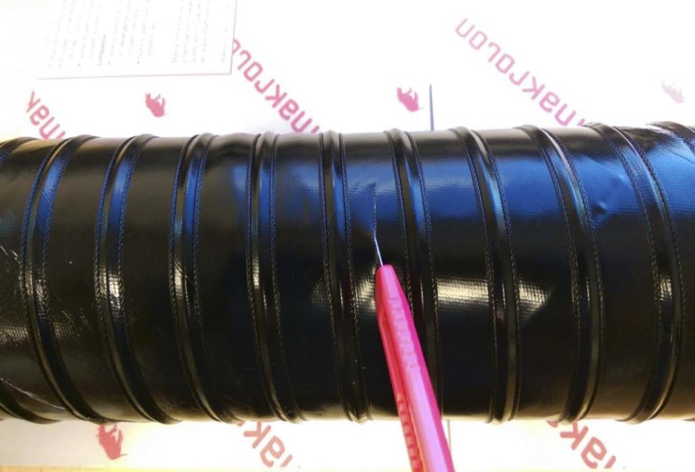
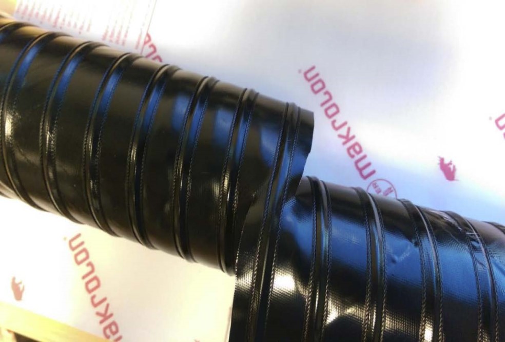
Pierce the Flex Duct (S) using a razor, centered between the two-wire reinforcements. Cut all the way around, keeping the blade centered between the wire reinforcements the entire length of the cut. Use a mini-bolt or a heavy-duty wire cutter to cut through the wire and duct. Use a pair of scissors to cut through any remaining duct not yet cut.
Tool Required: Razor Blade, Scissor, Mini-Bolt or Heavy Duty Wire Cutter
(Optional) Install Flexible Duct End Cuff (R) onto both ends of the Flex Duct (S) with #56 Hose Clamps (U) installed. Tighten the hose clamps.
Tool Required: 8mm Socket/Wrench
(Optional) Reinstall the stock roof and all the mounting hardware from Step 22.
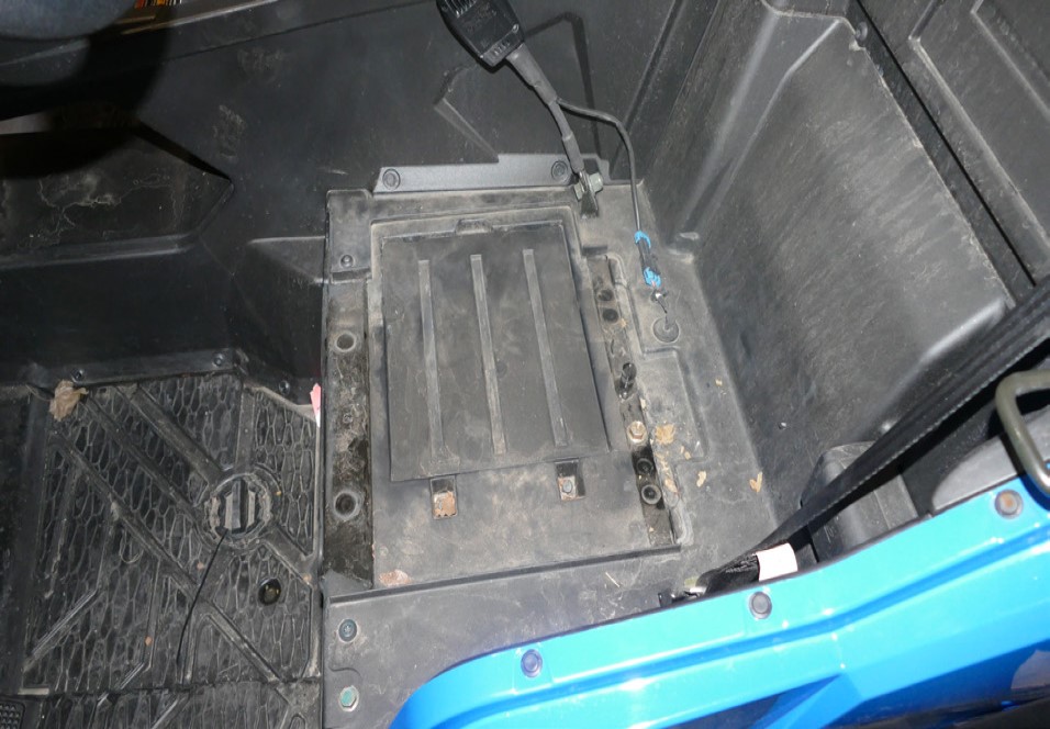
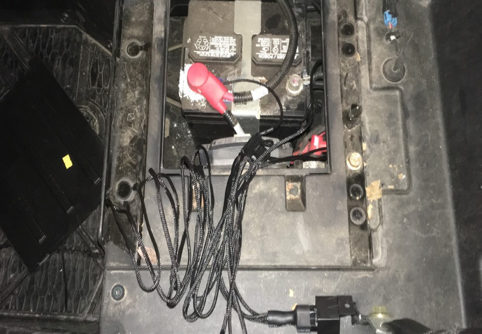
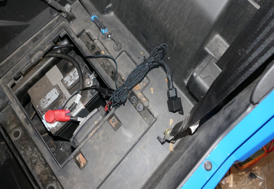
If you have the two-seater variant remove the battery access panel under the driver seat and if you have the four seater variant the access panel would be located on the driver side rear passenger seat.
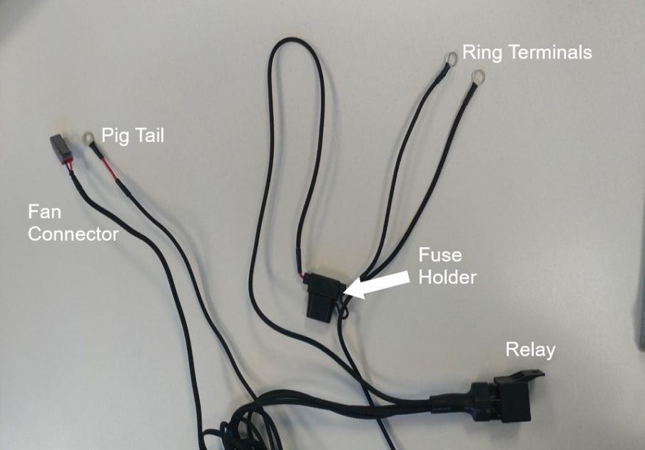
Familiarize yourself with the Wire Harness (AB) and each of the connectors. Coming from the relay should be a pigtail, fan connector, and ring terminals. Pig Tail Wire is used in conjunction with the Positap (AC) to tap into a power source. Ring Terminals have the fuse holder with the red and black ring terminals for the battery. Fan Connector has the connector to power the Particle Separator Assembly (A).
Loosen and remove the screw on the negative battery terminal, then disconnect the positive terminal from the battery. Install the Ring Terminals, from the Wire Harness (AB), onto the battery terminal clamps. Red wire with the fuse holder to (+) and Black wire to (-) and reinstall the screw. Secure the positive terminal first then the negative terminal.
Tool Required: 13mm Socket/Wrench
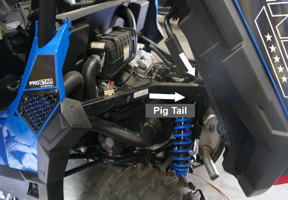
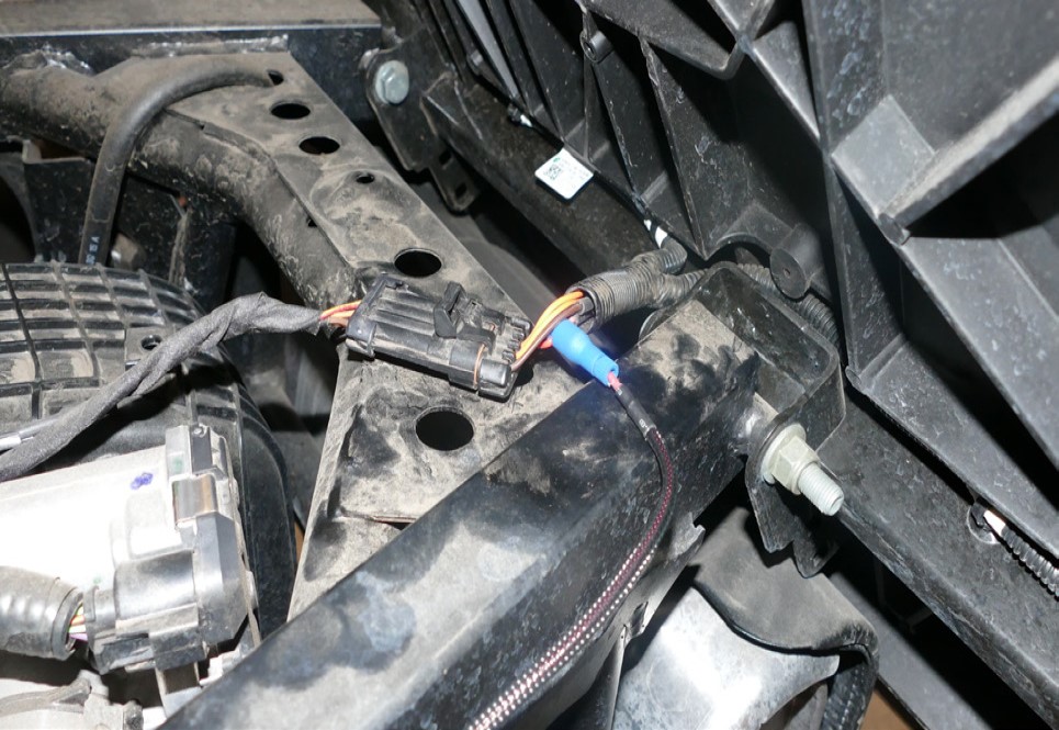
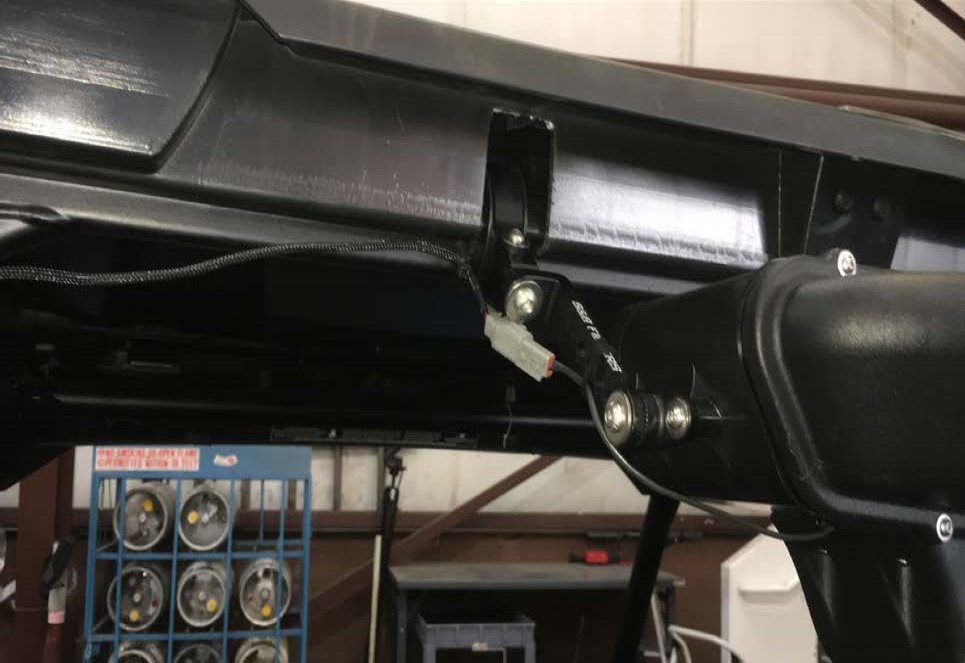
If you have a bus bar route the pigtail towards that and connect the ring terminal into the accessories terminal or if not route the pigtail towards the back of the vehicle. You are looking for the taillight connector sitting on top of the frame. This would be the best time to route and tuck the wire.
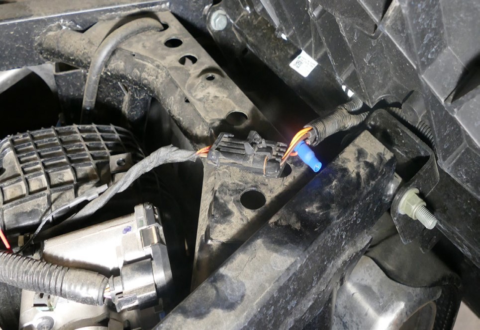
Skip this step if your vehicle has a bus bar and you decided to install the pigtail to the accessories port otherwise carefully examine the connector. You want to tap into the red/yellow wire. Unscrew the large top cap and place the cap around the red wire on the taillight connector then screw the body onto the cap until it is firmly tight and pierces the wire. Cut off the terminal and strip about 3/8” of insulation off of the end of the Pig Tail wire. Unscrew the bottom cap on the Positap (AC) and insert the Pig Tail wire into the main body of the Positap. Make sure the strands go around the metalcore. While holding the wire in place, screw the bottom cap back on until it is firmly tight. Double-check both caps to make sure they are tight.
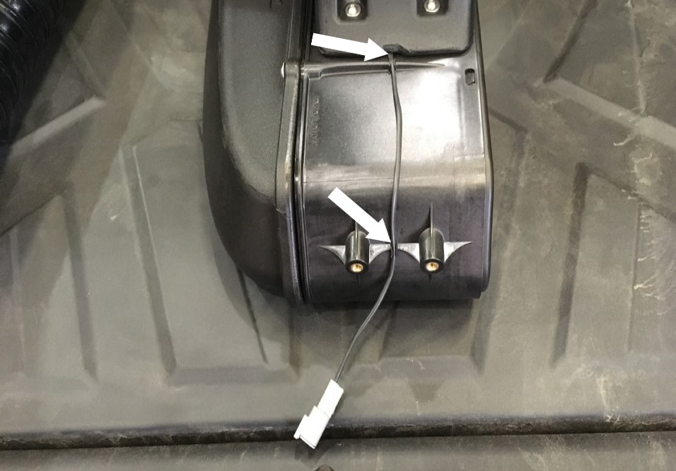
To ensure that you have installed the Wire Harness (AB) correctly, connect the Fan Connector to the fan on the Particle Separator Assembly (A). Note the color of the wires whenever connecting or disconnecting this connector. Make sure not to cross the connectors. Power (red) to power (red) and ground (black) to ground (black). The connectors should snap into each other with very little resistance. Do not try to force the connectors into each other. Turn the key one position clockwise (without bumping the starter) or if you have wired in a switch, flip the switch to the ON position. If you hear the Particle Separator fan turning on, you have wired it correctly. Proceed to the next step.
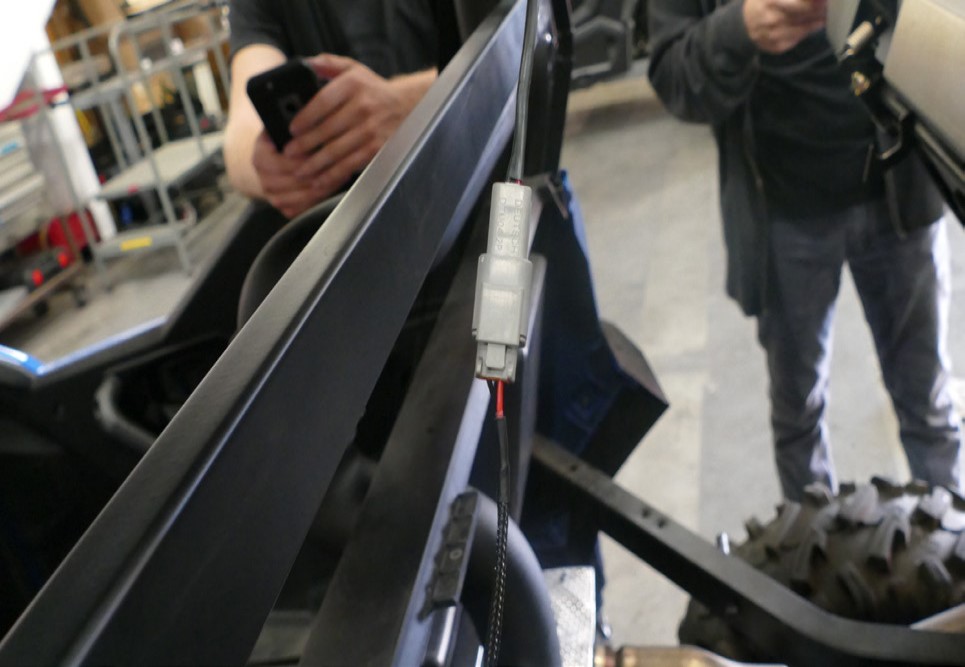
Disconnect the connector and finish the wiring. Route the wire as you see fit towards the Particle Separator (A). Connect the fan connector into the Particle Separator Assembly (A). Use Cable Ties (AA) or Velcro Strap (AB) to secure the Wire Harness (AB).
Tool Required: Wire Cutter
Group together any excess wires with Cable Ties (AA). Use another cable tie and secure the bundle in places away from any exhaust components or moving parts that could potentially damage the harness.
Tool Required: Wire Cutter
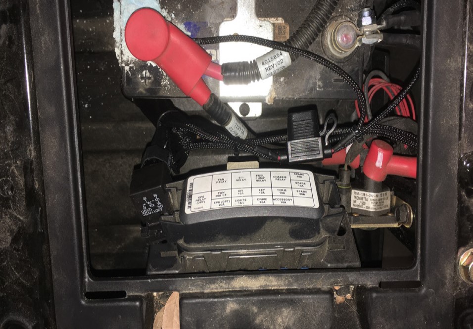
Cable Tie (AA) the relay onto the fuse box to secure the Wire Harness (AB).
Tool Required: Wire Cutter
Reinstall the seats that were removed in Step 1.
Reinstall the CVT ducting removed in Step 4. Remember to tighten all the hose clamps.
Tool Required: 6mm Socket/Wrench
Reinstall the pin and clip removed in Step 3 to secure the damper to the dump bed.
Double-check to make sure all connectors are plugged in and secured. Turn the ignition on and make sure air is blowing out the exhaust. If the exhaust fan does not turn on, double check your electrical wiring. Your installation is now complete. Enjoy your new product!