STEP 1
Slide the drivers seat all the way forward by pulling up on the seat adjuster found under the front of the seat.
Slide the drivers seat all the way forward by pulling up on the seat adjuster found under the front of the seat.
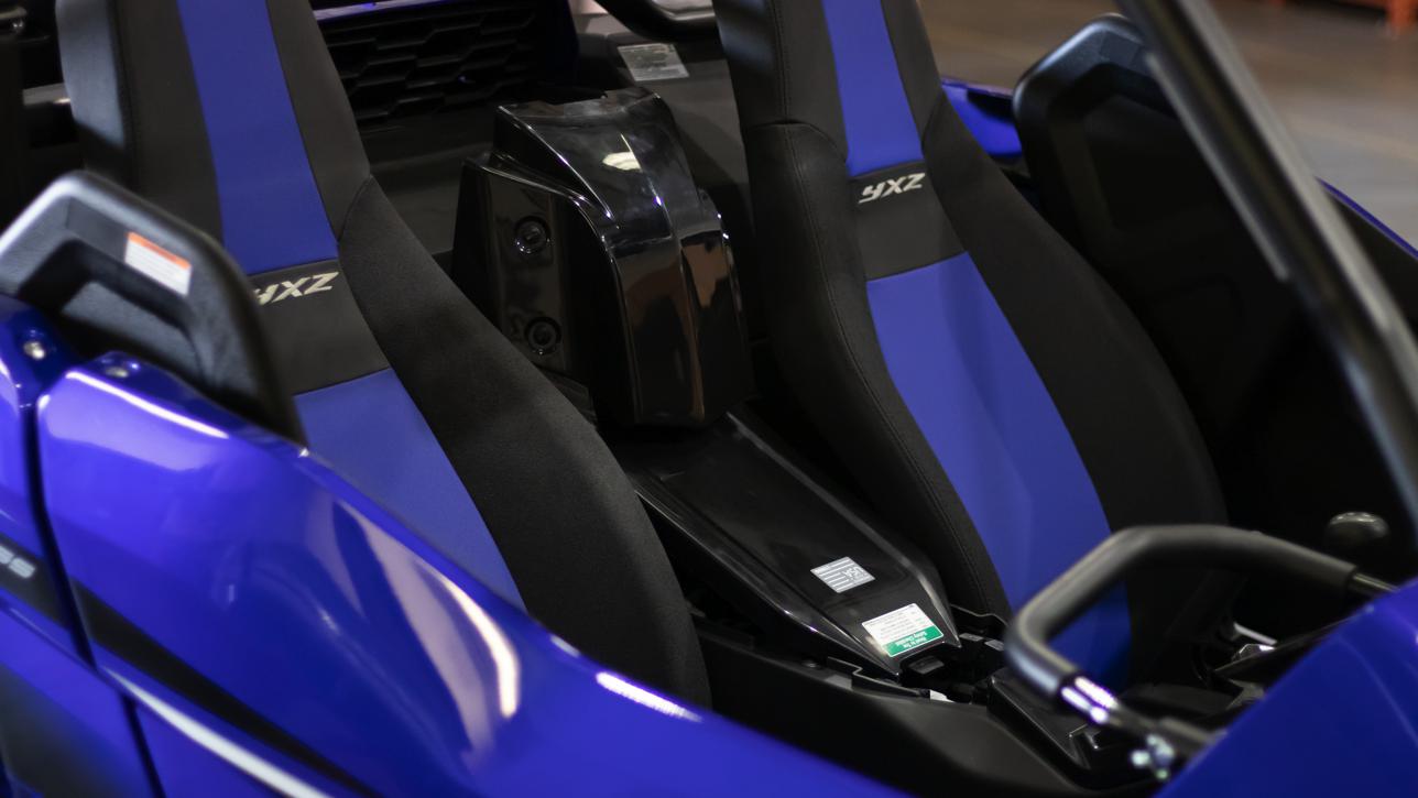
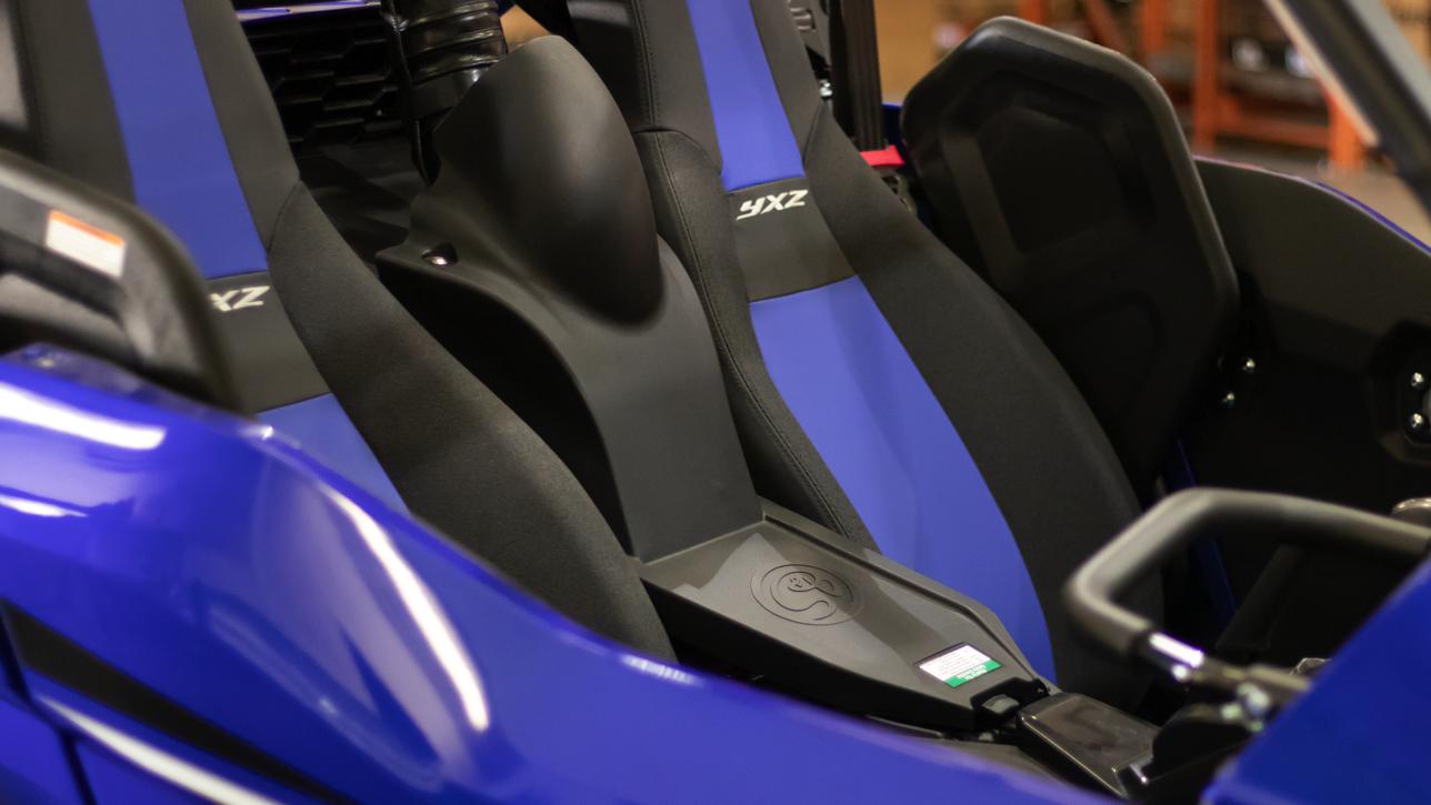
Remove the center console cover by lifting up on the back and sliding the front tab out from its slot. Make sure the rear mounting grommets did not pull out with the cover.
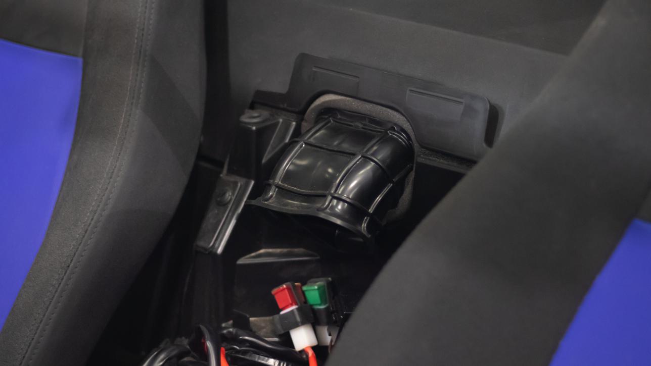
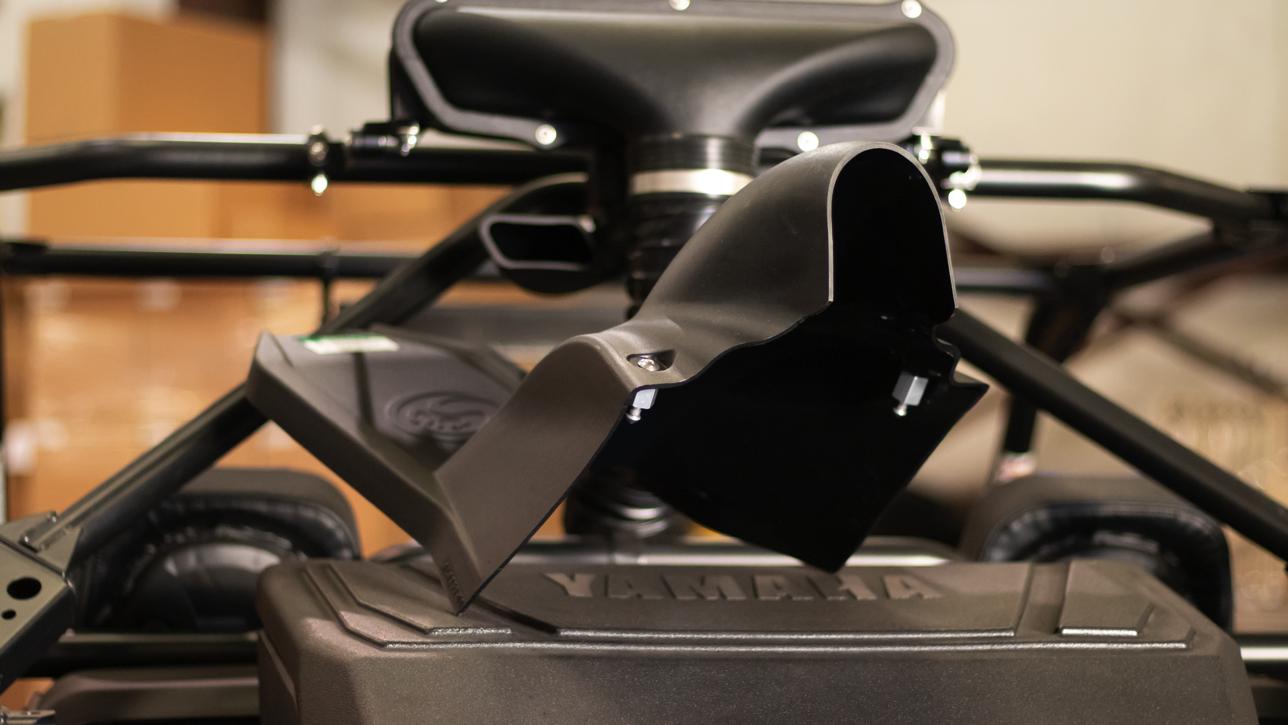
Remove the the stock air duct from the air box by squeezing the top and bottom of the air duct and pulling it into the cab.
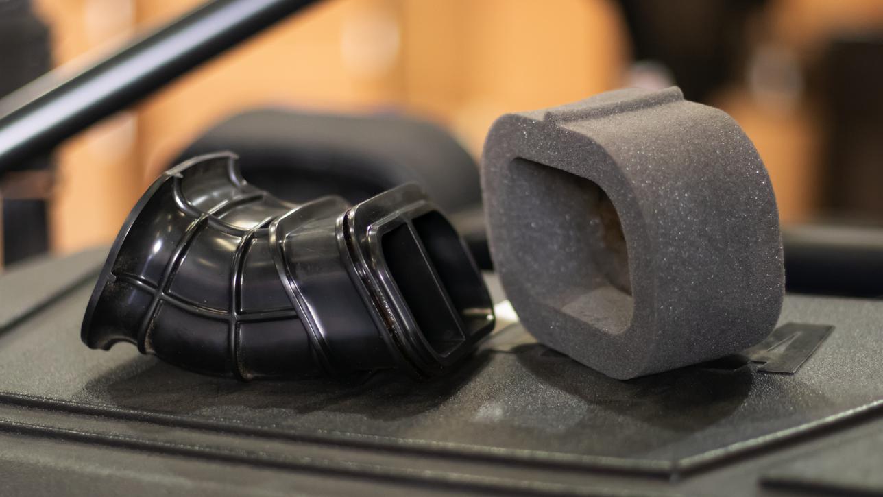
Remove the foam seal from the stock air duct, using your fingers between the two to carefully separate the factory adhesive holding them together. Be careful not to tear the foam.
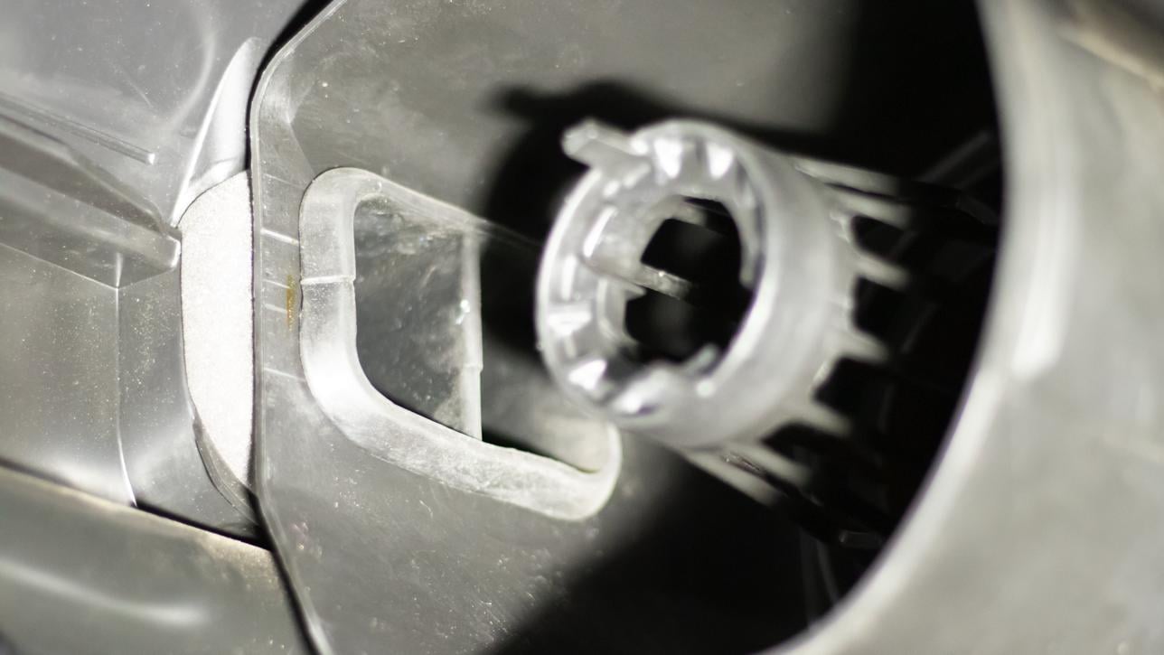
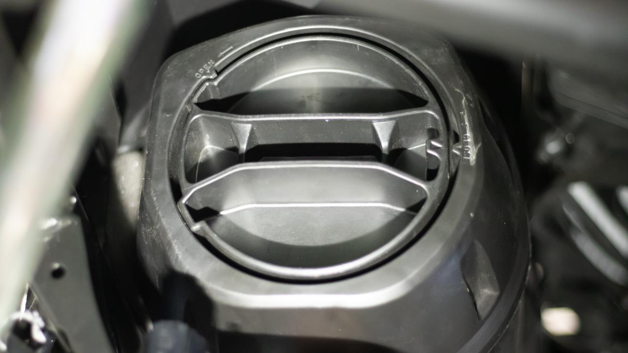
Remove the air box lid by rotating the handle counter clockwise. The air box lid can be accessed from the driver’s side rear wheel well.

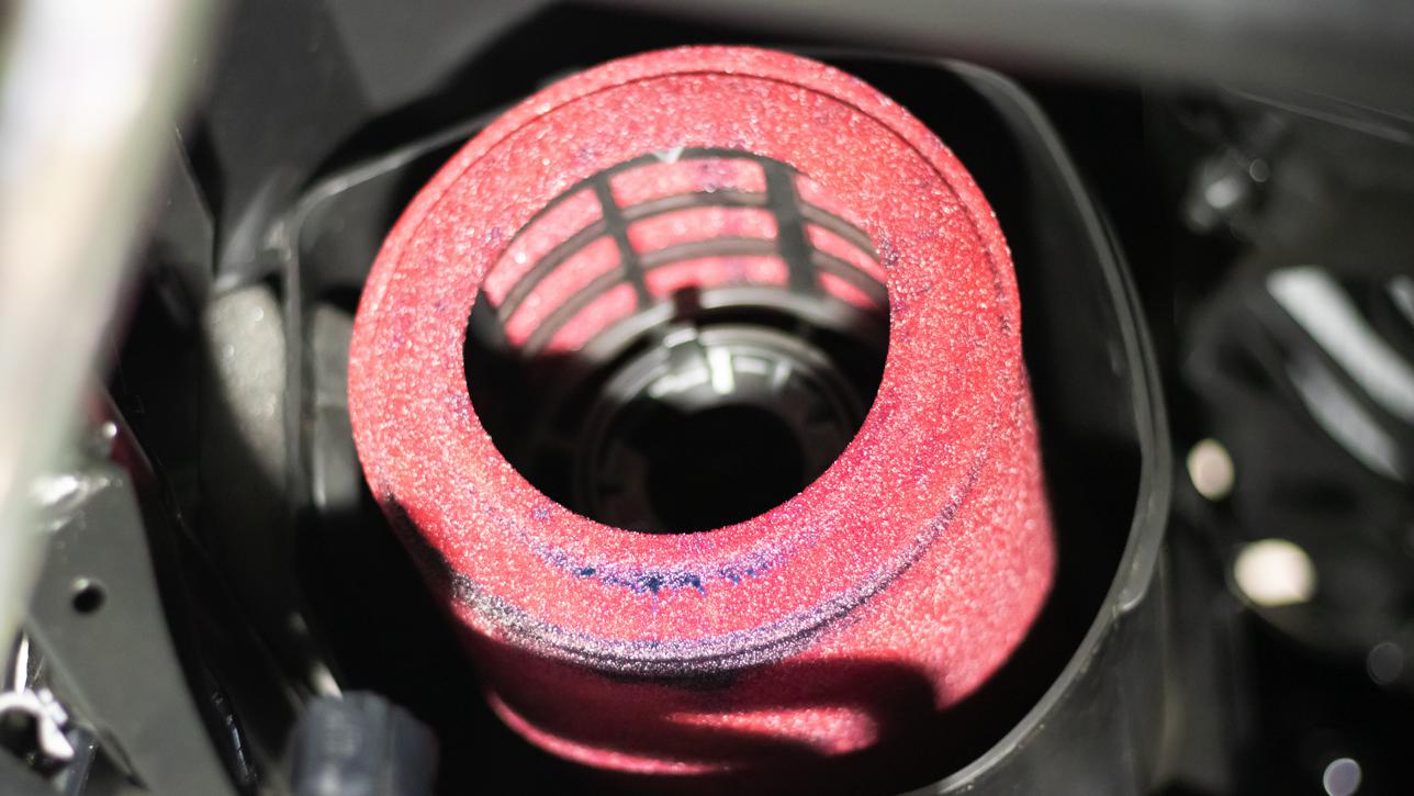
Slide the air filter out of the air box.

Insert the Air Box Coupler (L) into the air box opening from inside the cab.
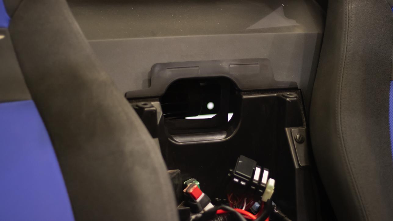
Make sure the groove on the coupler is fully seated, and the coupler flange seals on the inside of the air box.
Reinstall the air filter in the air box.
Reinstall the air box lid by rotating the handle clockwise.
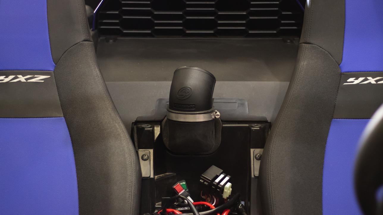
Install the stock foam seal, removed in Step 4, into the gap around the Air Box Coupler, ensuring the semi circle bead is on the bottom. Push the entire foam seal into the gap until it is flush with the gap opening.
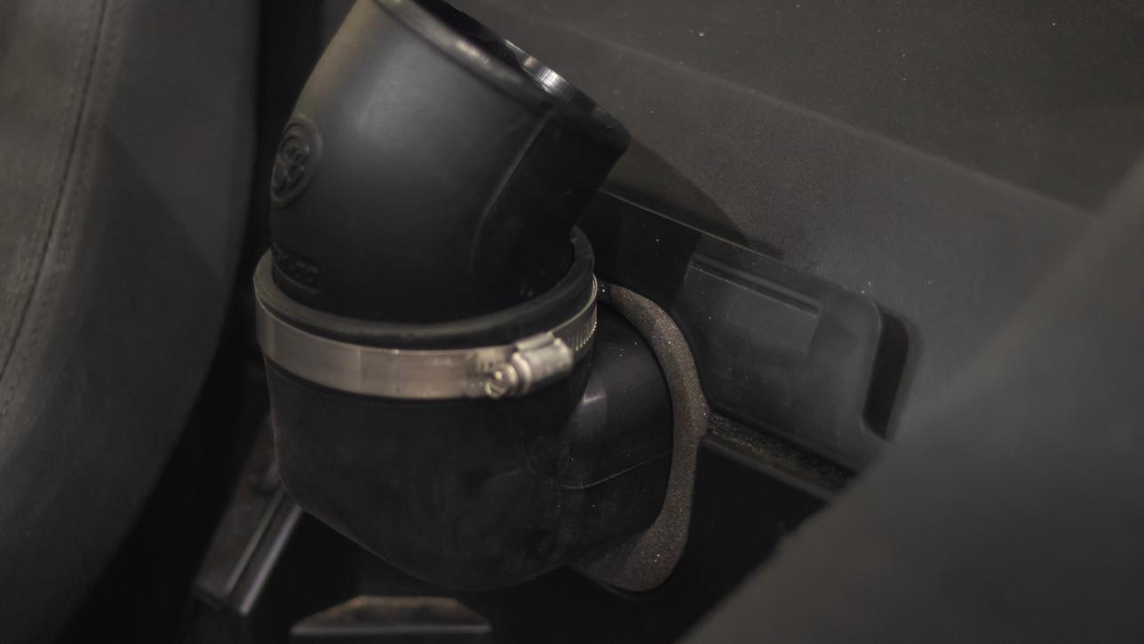
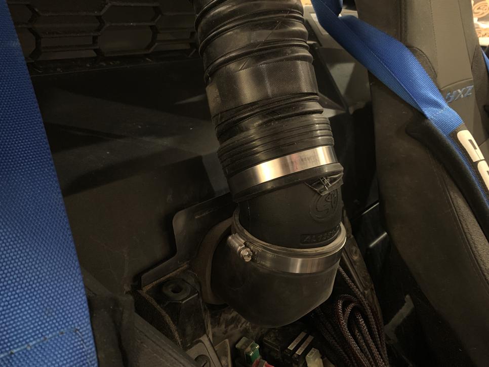
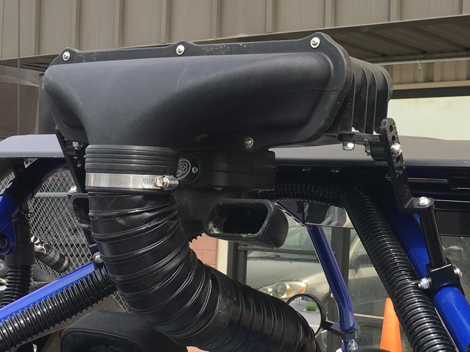
Insert the Intake Tube (M) and Hose Clamp (O) into the Air Box Coupler with the S&B logo facing straight ahead towards the front of the vehicle. Tighten the hose clamp.
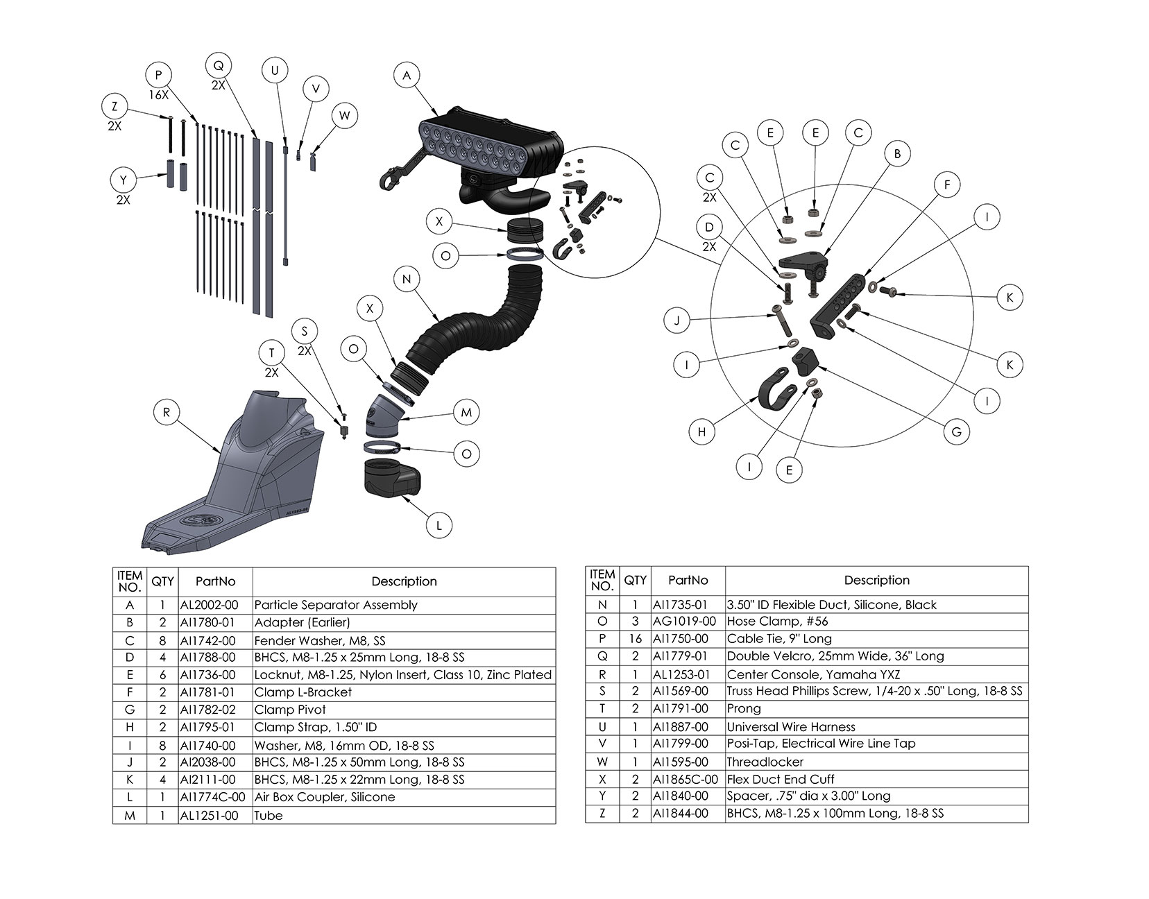
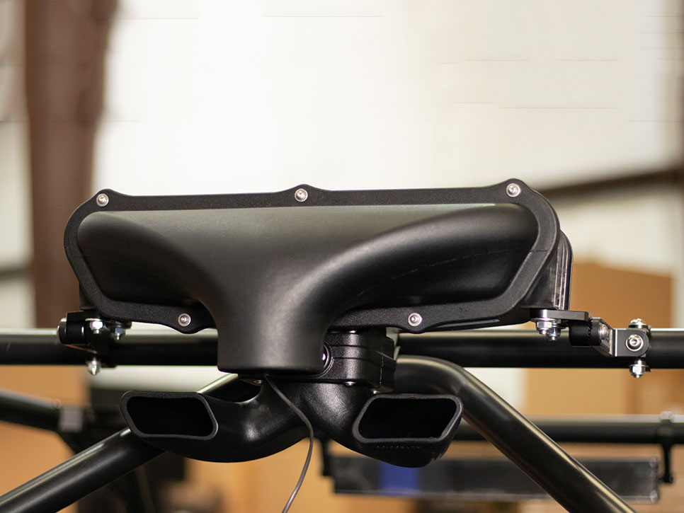
Install the Adapters (B) onto the mounting bosses on both sides of the bottom the Particle Separator Assembly (A) with the Screws (D), Washers (C), and Locknuts (E), then tighten.
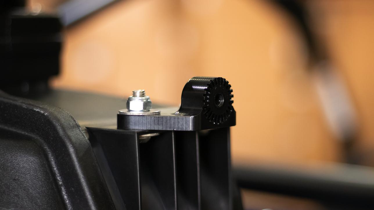
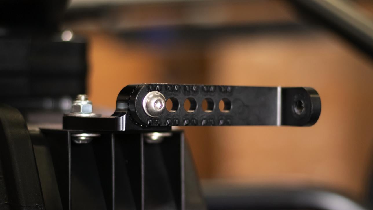
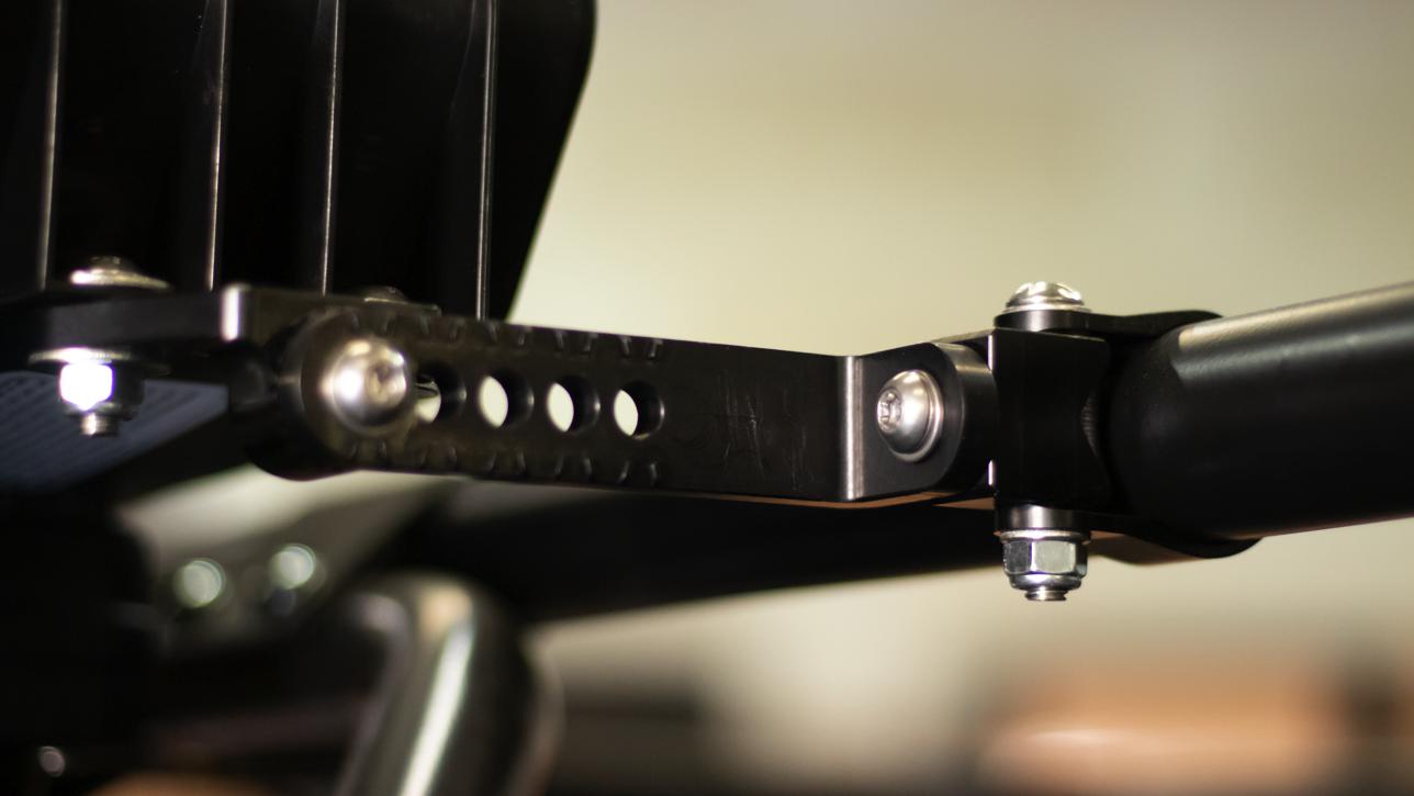
Install the L Brackets (F) onto the Adapters with the Screws (K) and Washers (I), selecting the proper angle and orientation based on the desired location for the Particle Separator. Apply Thread Locker to the screws before installing, then tighten.
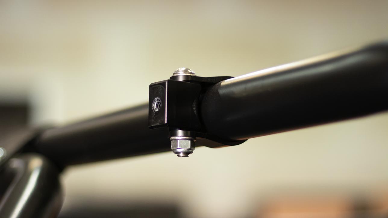
Slide the Straps (H) over roll cage. Wrapping a small parts bag around the roll cage will make sliding the strap over the roll cage easier and help protect the roll cage from scratches.
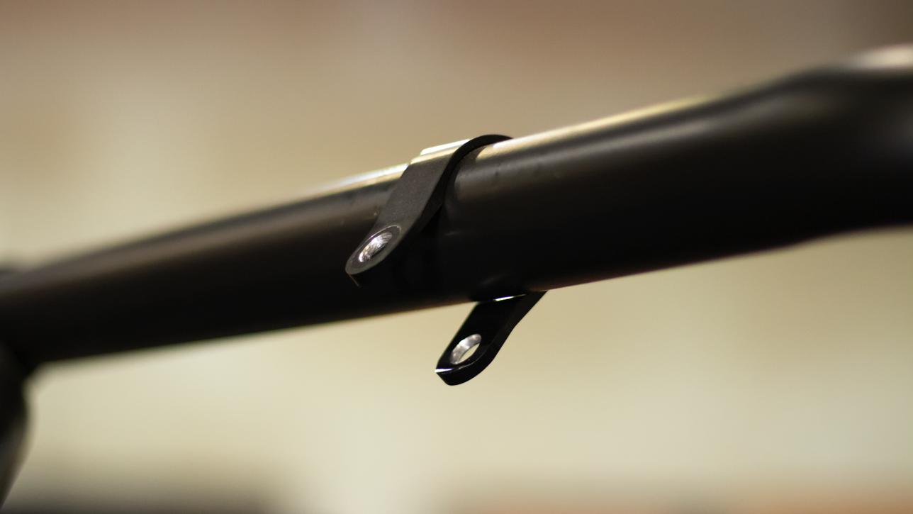
Install the Pivot Bodies (G) with the Screws (J), Washers (I), and Locknuts (E). Snug the straps up, but do not fully tighten, leave the straps loose enough so they can be slid side to side and rotated.
Install the L Brackets onto the Pivot Bodies using the Screws (K) and Washers (I). Apply a small amount of Thread Locker (W) to the screw before installing, then tighten.
If you have the optional roof, you can use the 3" Spacers (Y) and Screws (Z) and Washers (I) to mount the particle separator behind the roof tail.
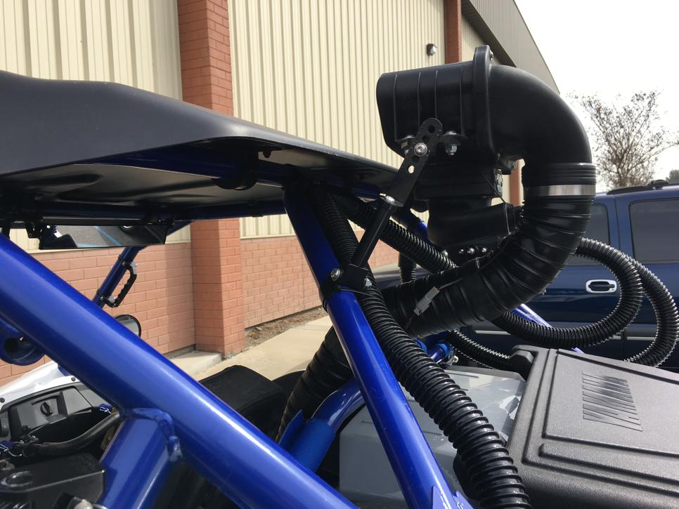
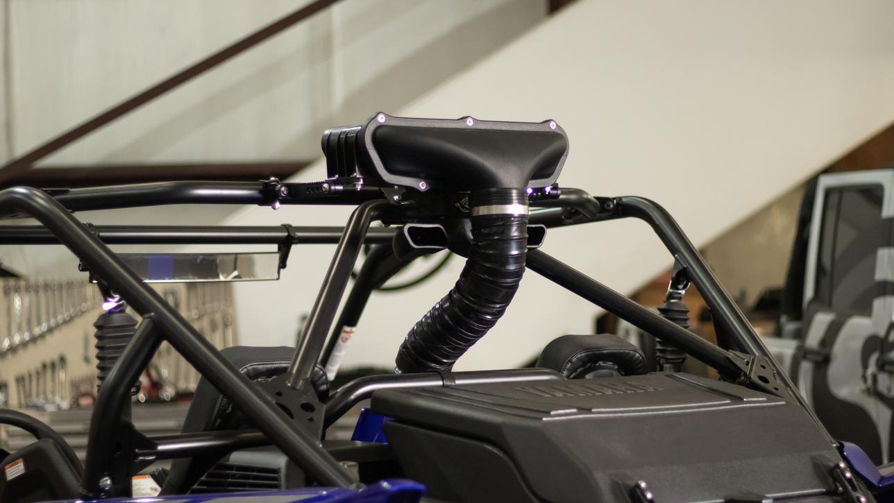
Once you are satisfied with the position of the Particle Separator, tighten the Straps, double check that all mounting screws and nuts are tight and that they are securely mounting the Particle Separator on the roll cage.
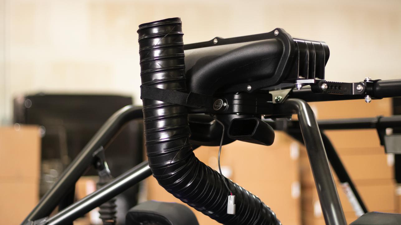
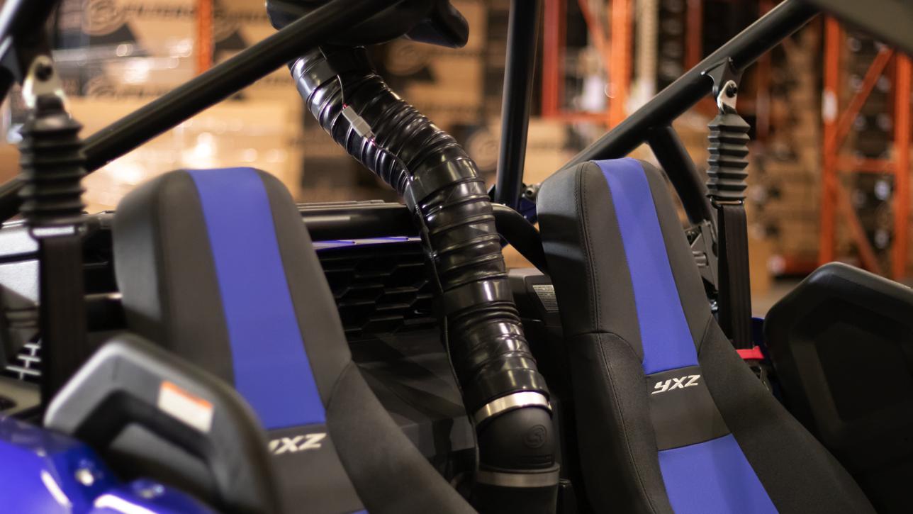
19A: Install the End Cuff (X) and Hose Clamp (O) onto one side of the Flex Duct (N) and slide it onto the Intake Tube (M) as shown. Tighten the Hose Clamp.
19B: Bring the other end of the Flex Duct (N) towards the outlet of the Particle Separator (A). Note the length needed to reach the plenum and add an extra 3", this is where you will cut the Flex Duct.
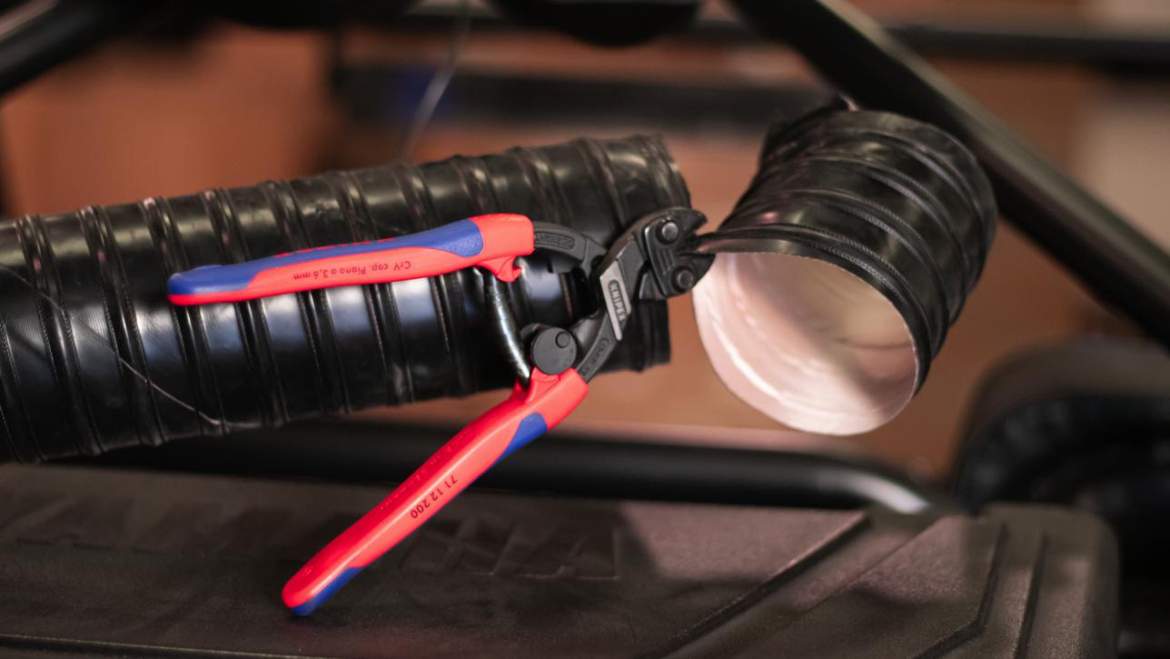
Using a Utility Knife pierce the Flex Duct centered between the two reinforcement wires. Cut all the way around the Flex Duct keeping the blade centered between the wires. Use diagonal cutters to cut through the reinforcement wire.
Install the End Cuff (X) and a Hose Clamp (O) onto the Flex Duct (N) and slide it onto the plenum of the Particle Separator (A) as shown. Tighten the Hose Clamp.
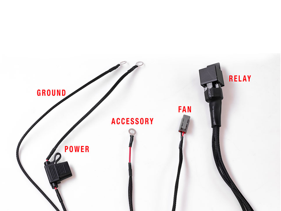
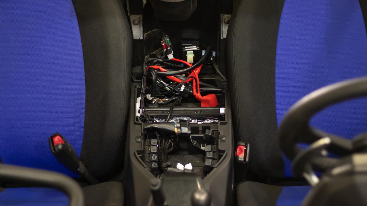
Familiarize yourself with the Wire Harness (U). It has a red Power Wire with fuse, a black Ground Wire, a red Accessory Wire, and a Fan Connector. The Power and Ground Wires go to the battery, the Accessory Wire goes to the Posi-Tap and a keyed/switched power source, and the Fan Connector goes to the Particle Separator.
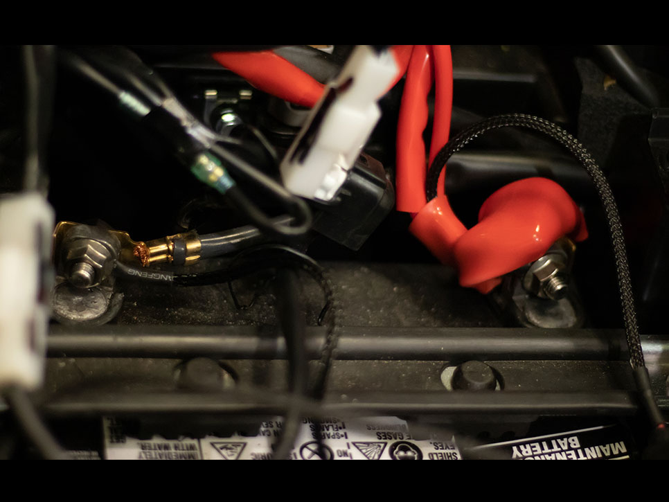
Install the Power and Ground wires onto the battery terminal posts. The red Power Wire goes to the positive (+) terminal first and then the black Ground Wire goes to the negative (-) terminal.
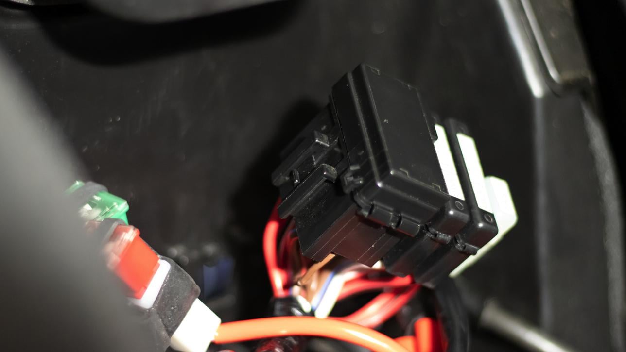
Remove the fuse box from the back panel between the seats by depressing the locking tab and sliding the fuse box up.
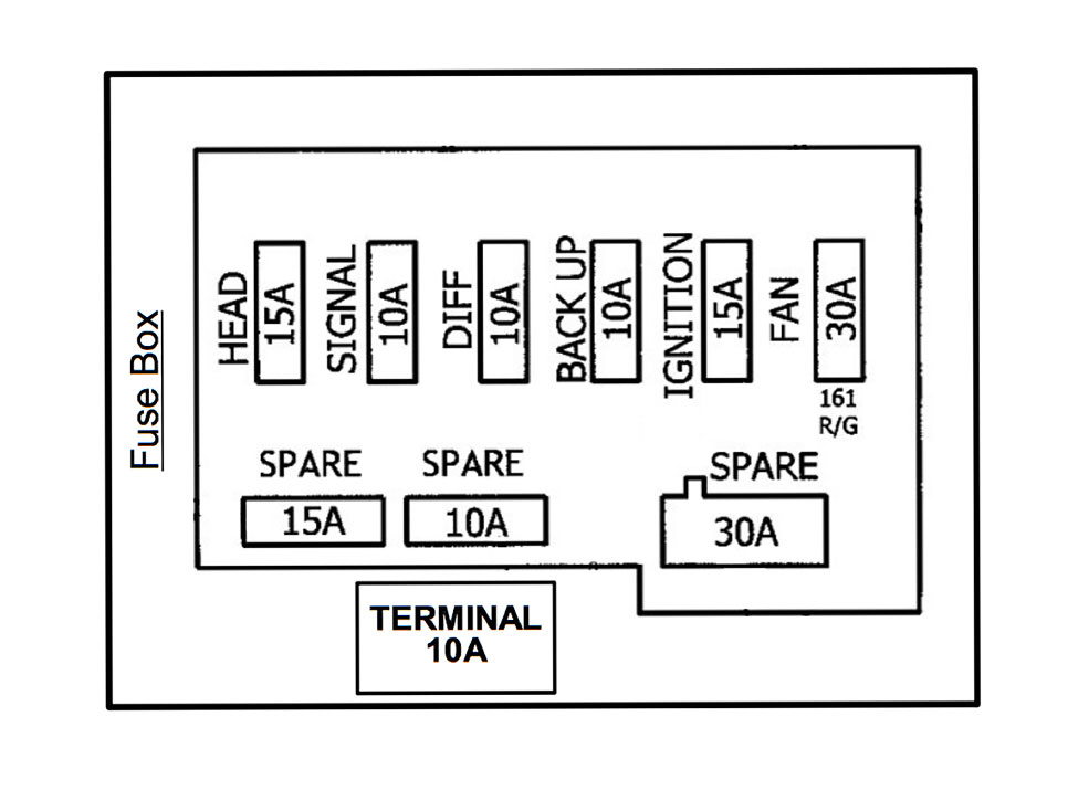
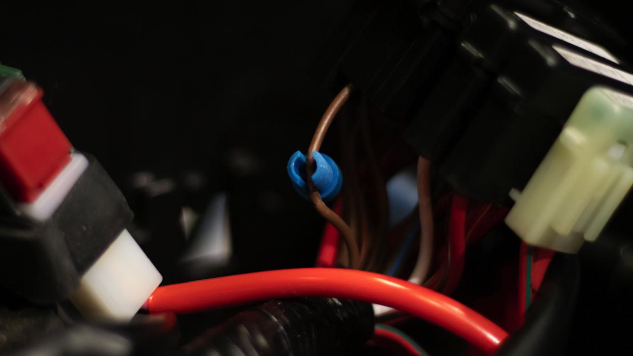
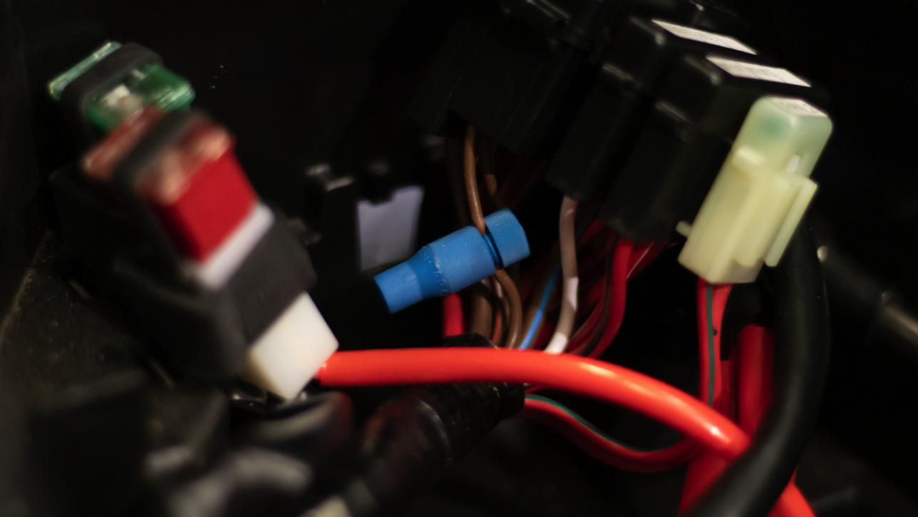
Install the Posi-Tap (V) onto one of the brown wires coming from the bottom of the fuse box that is connected to the HEAD (15A Fuse).
Unscrew the large end cap from the Posi-Tap body and slide the brown wire in-between the legs of the cap.
Then reinstall the Posi-Tap body onto the large end cap and tighten.
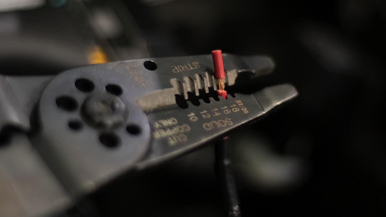
Strip about 3/8” off the end of the red Accessory wire.
Unscrew the small end cap from the Posi-Tap and insert the red Accessory wire.
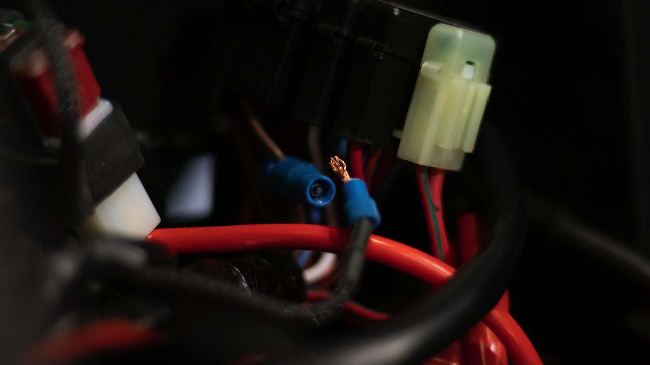
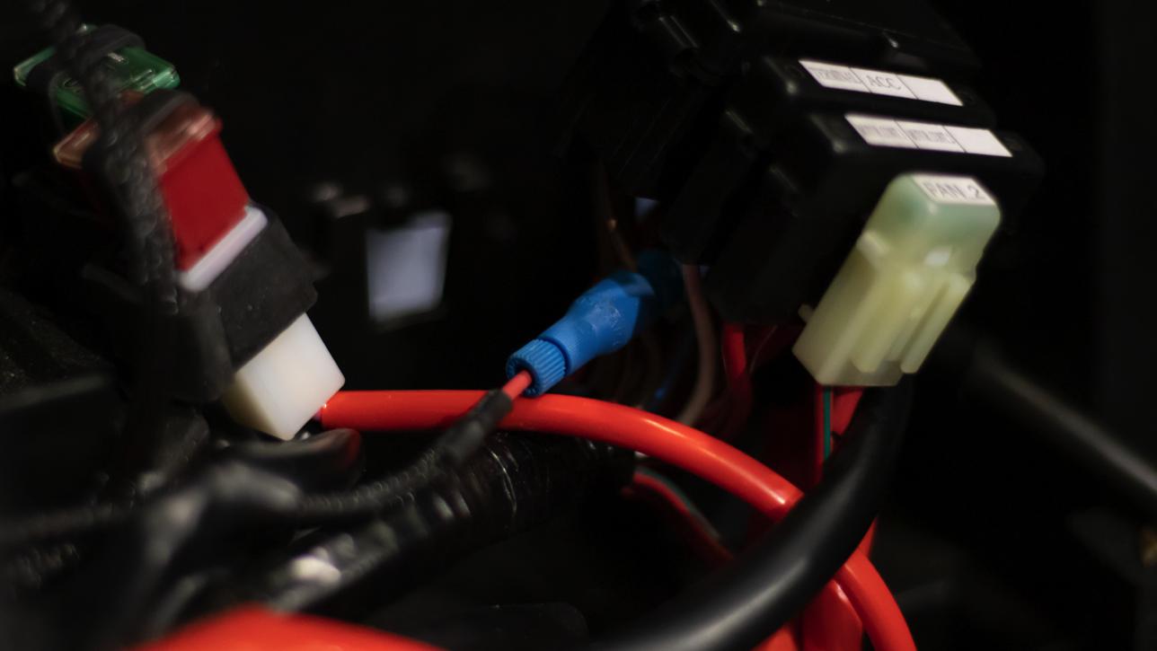
Insert the small end cap and wire into the Posi-Tap body making sure the strands of the wire go around the metal core inside the body.While holding the wire in place, screw the cap back on until it is tight and the wire is secure.
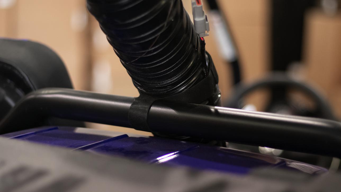
Route the Find Fan Connector along the Flex Duct up to the Particle Separator, plug it in and secure the wire to the duct with Velcro (Q).
Secure the Flex Duct to the roll cage with Velcro.
Reinstall the fuse box onto the back panel and secure any excess wire with Cable Ties (P) near the battery in the center console area.
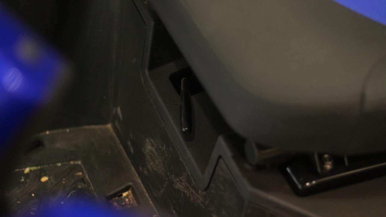
Install Prongs (T) onto the Center Console (R) using the Screws (S) and Thread locker.
Install the Center Console by sliding the front tab in its slot then and pressing down on the rear of the cover.
Double check to make sure all connectors are plugged in and secured. Turn the ignition on and make sure air is blowing out the exhaust port of the Particle Separator. If the exhaust fan does not turn on, double check your electrical wiring. Your installation is now complete. Enjoy your new product!