STEP 1
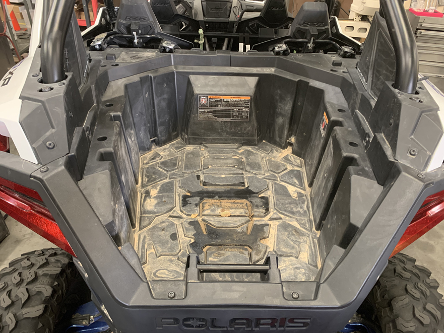
Remove the bed by removing the 4 screws securing it to the frame. Lift up on the handle and pull the bed out to the rear of the vehicle.
Tools Used: T40 Torx
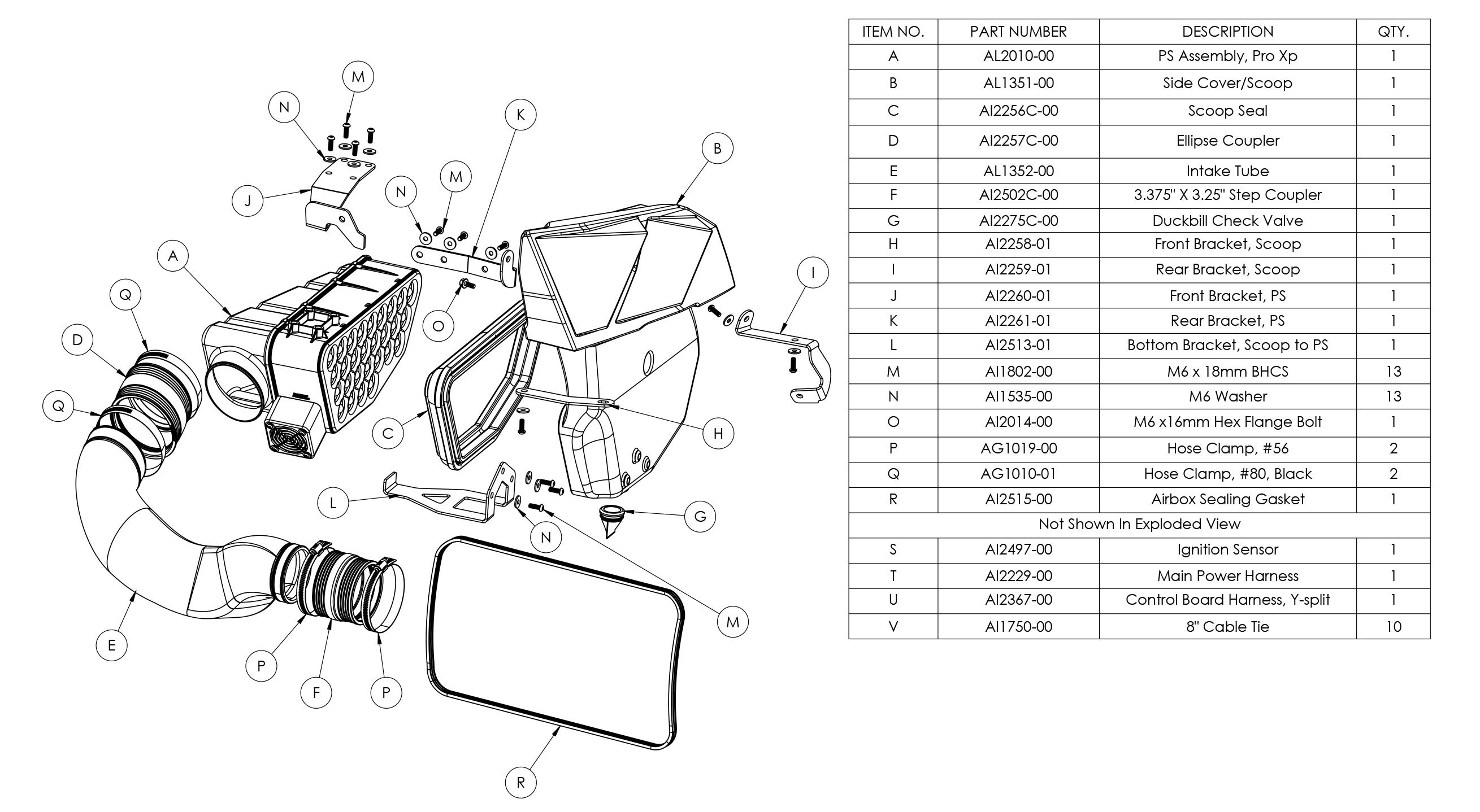
• Please read the entire installation manual before proceeding.
• Ensure all components listed on the following section are present.
• If you are missing any of the components, call our customer support at (909) 947-0015.
• Do not work on the vehicle while the engine is hot.
• Make sure the engine is turned off, the vehicle is in Park and the Parking Brake is set.
Remove the bed by removing the 4 screws securing it to the frame. Lift up on the handle and pull the bed out to the rear of the vehicle.
Tools Used: T40 Torx
.jpg?v=1686664732892)
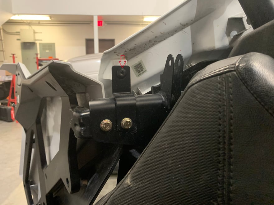
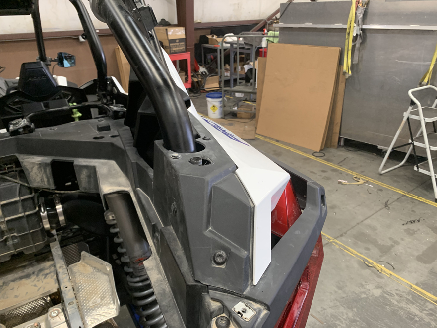
Remove the bolts and push in rivets securing the rear quarter panels to the body.
Tools: T40 Torx & Panel Popper
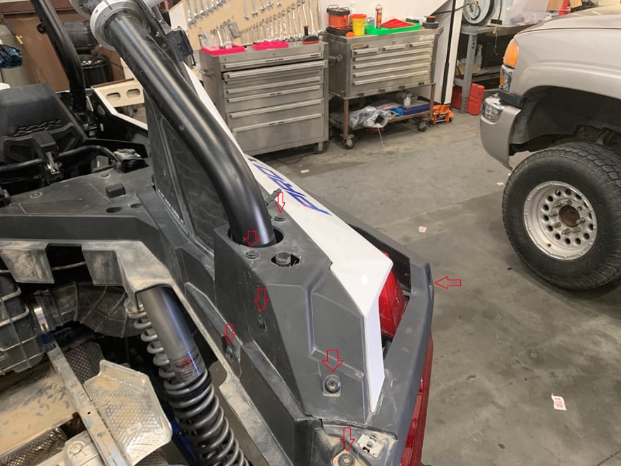
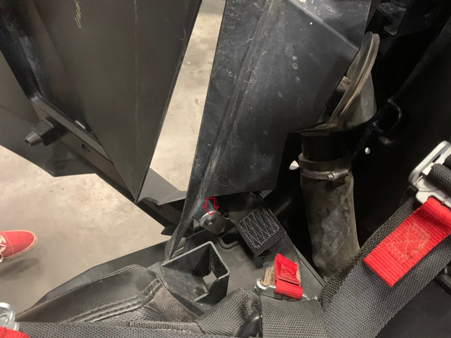
Remove the push in rivet on the underside of the body panel to release it.
Tools: Panel Popper
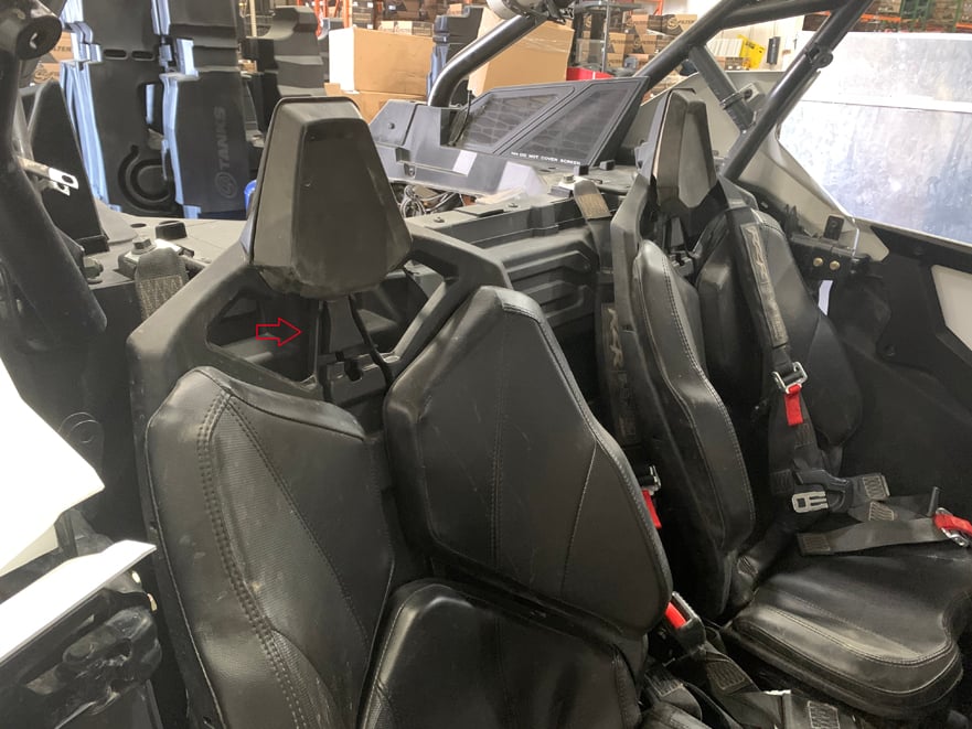
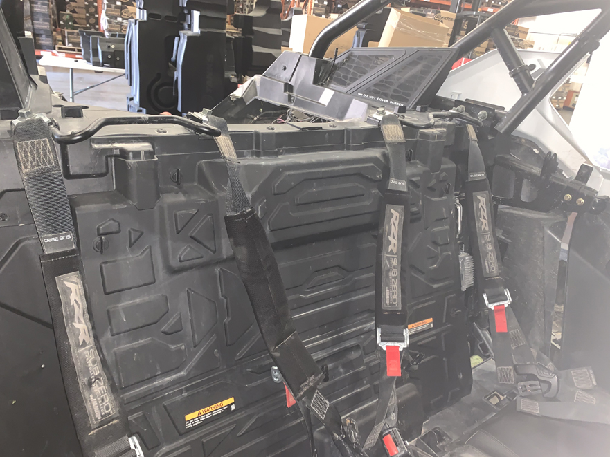
Remove the back half of both seats (Rear if 4 seater) by pressing the release button on the back of the headrest, then pull up and out.
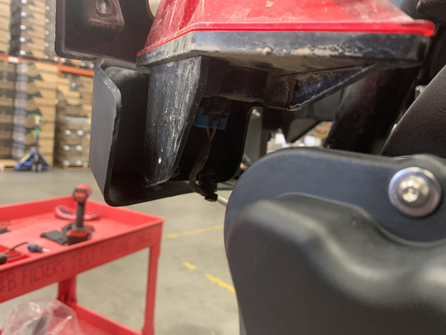
Disconnect the rubber grommet holding the gas line to the body panel by pressing it back through the plastic.
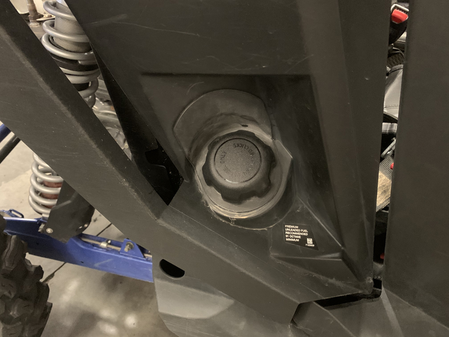
Remove the side body panel assembly. Note that there are two clip-in attachments at the bottom below the gas cap that will need to be pressed out while removing the body panels.
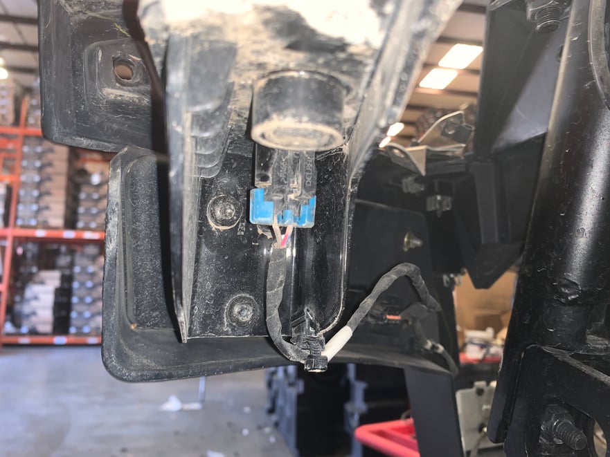
Remove the rear brake light by disconnecting the power harness and removing the three screws holding it to the body.
Tool: T30 Torx
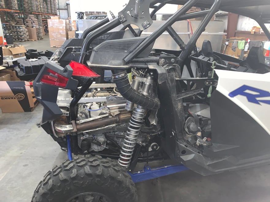
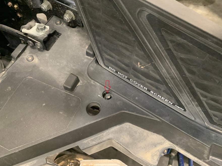
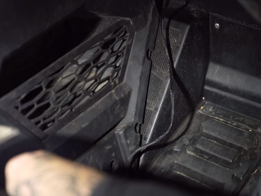
Remove both of the rear access panels by turning each of the 6 quarter-turn fasteners counterclockwise and pulling out.
Remove the intake tube from the vehicle by loosening the hose clamp connected to the airbox, as well as the hose clamp connected to the side cover.
Tool: 5/16” driver
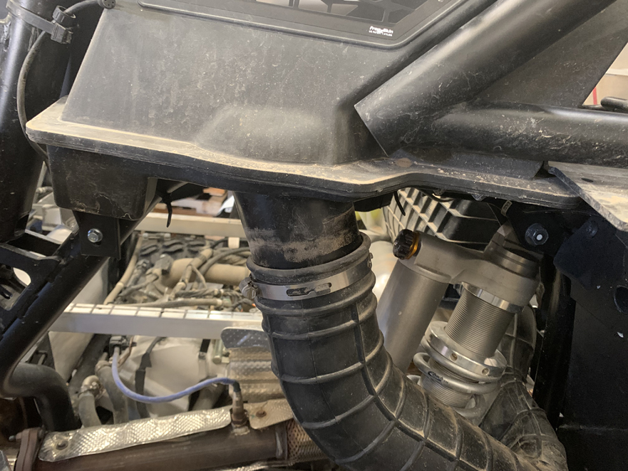
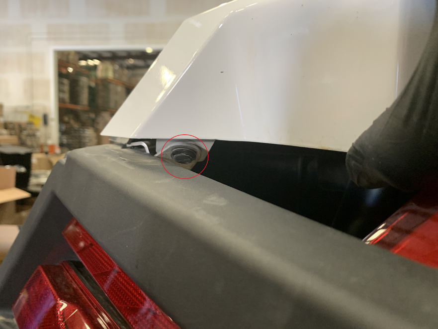
Remove the two bolts securing the side cover to the vehicle.
Tool: 10mm socket
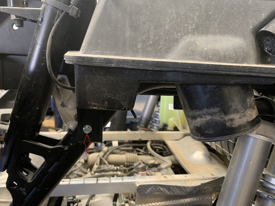
Remove the two bolts securing the side cover to the vehicle.
Tool: 10mm socket
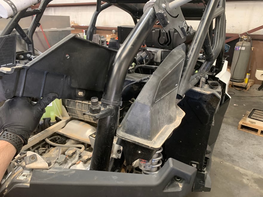
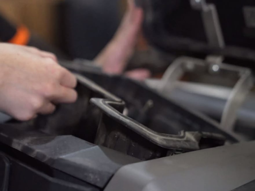
Remove the side cover from the vehicle. Lifting up the rear plastic will make this much easier.
Install the rear Particle Separator bracket onto the chassis using the provided M6 bolt. Only hand tighten for now so it can still rotate freely.
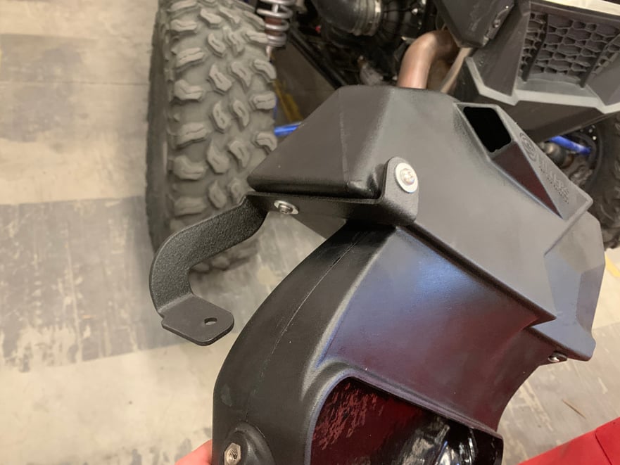
Install the rear scoop bracket onto the S&B Side cover scoop using the supplied M6 screws and washers. Only hand tighten for now, leaving slightly loose.
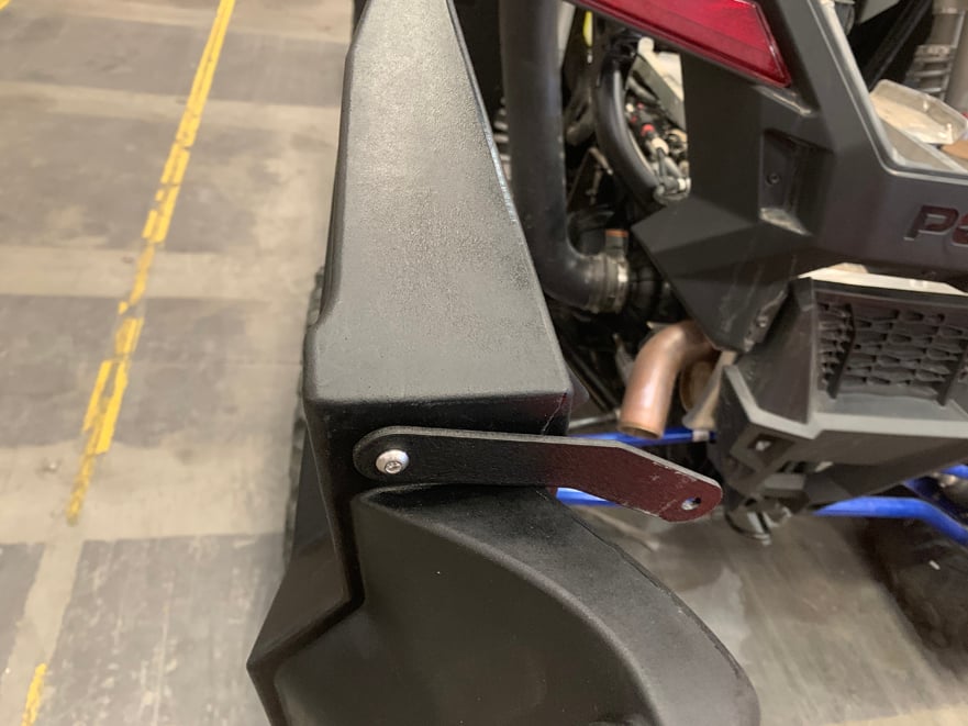
Install the front scoop bracket onto the S&B Side cover using the supplied M6 screws and washers, only hand tightening for now leaving it free to rotate. Make sure the side with the slotted hole is pointing toward the rear of the scoop. The side with the standard hole is screwed into the scoop.
Important: Install the scoop seal and duckbill check valve into the side cover as shown in the video clip.
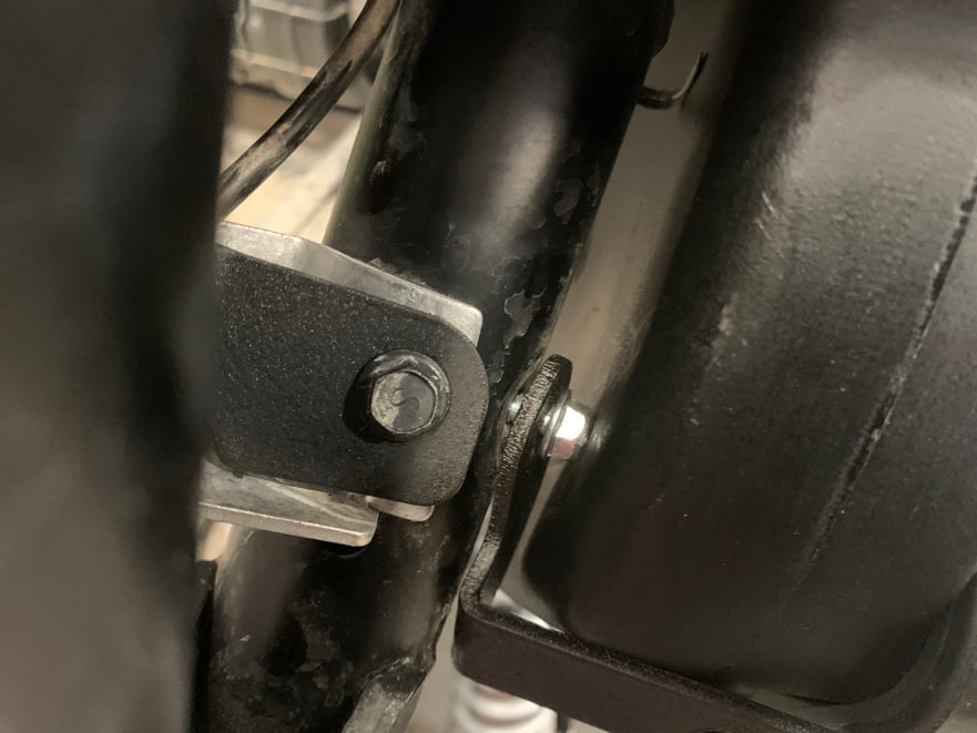
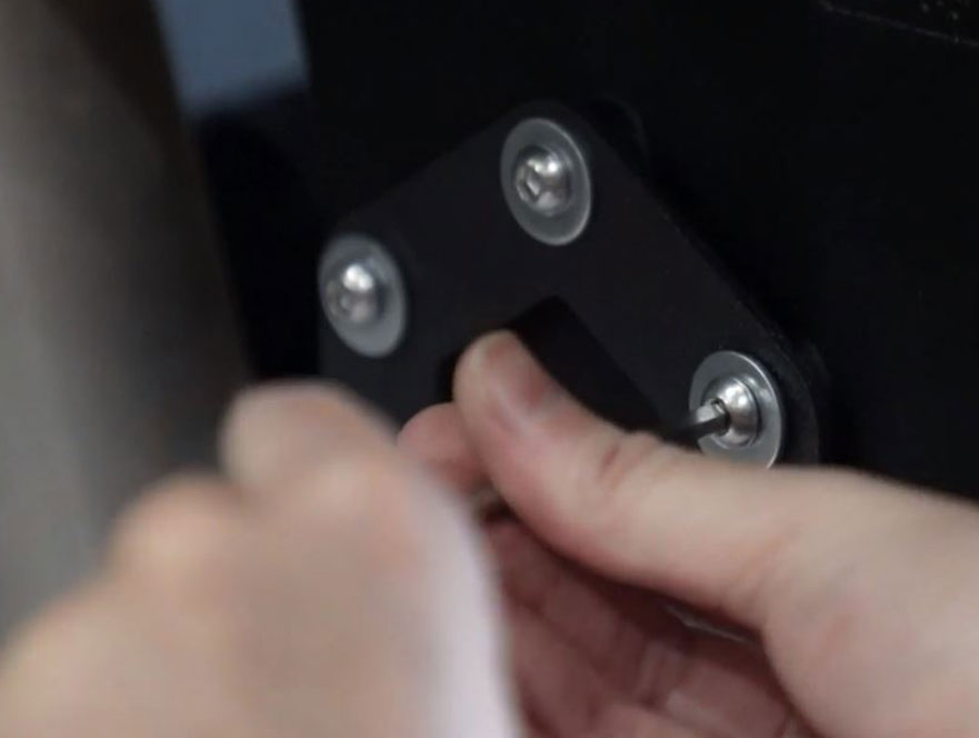
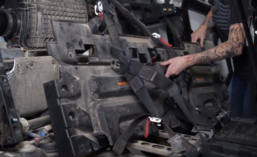
Remove the bolt securing the bed bracket to the chassis.
Tools: 10 mm Socket
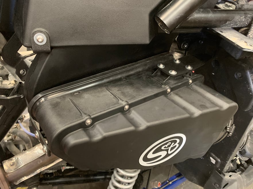
Install the S&B Side cover scoop onto the vehicle. Reinstall the removed bolts from steps 11 and 17 to secure the scoop to the chassis.
Tool: 10mm socket
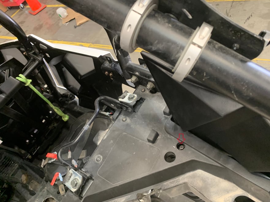
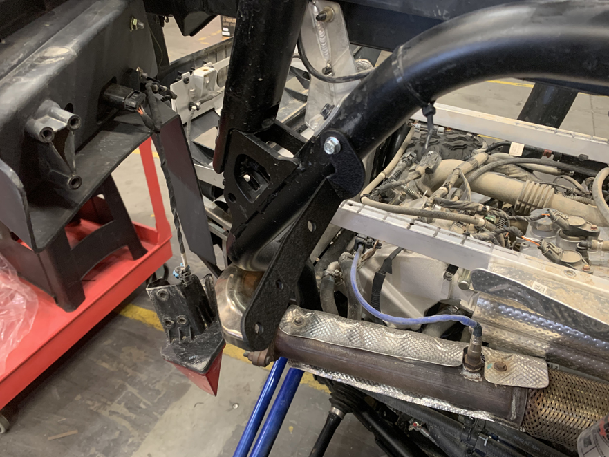
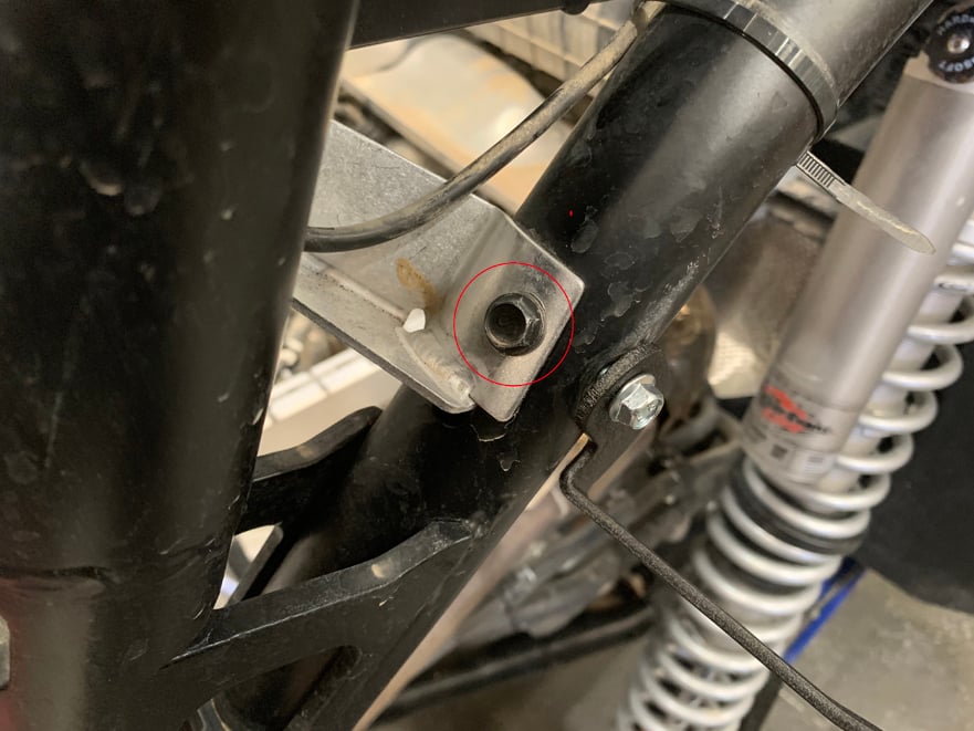
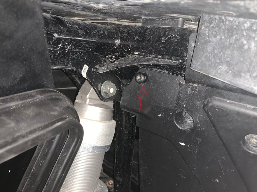
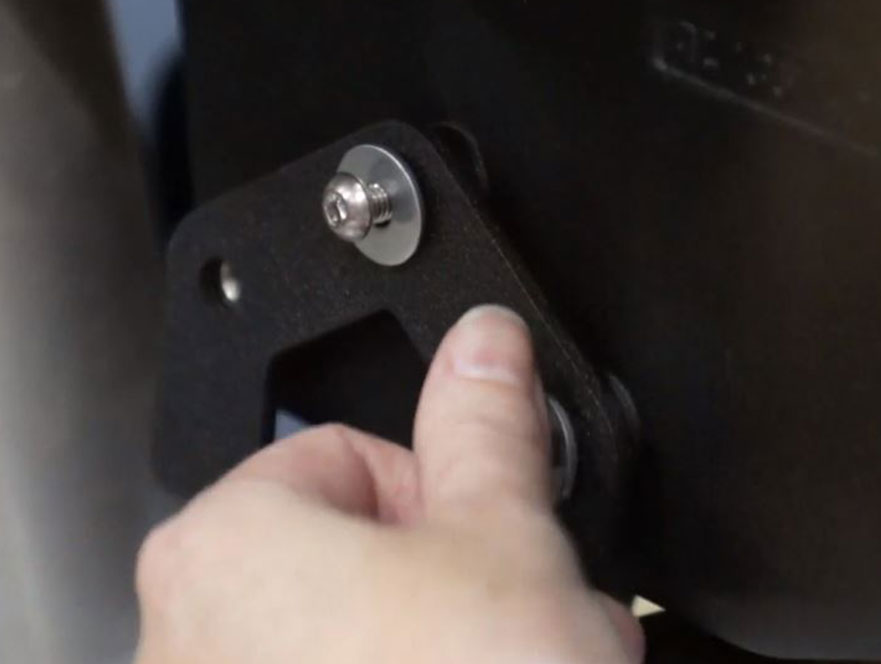
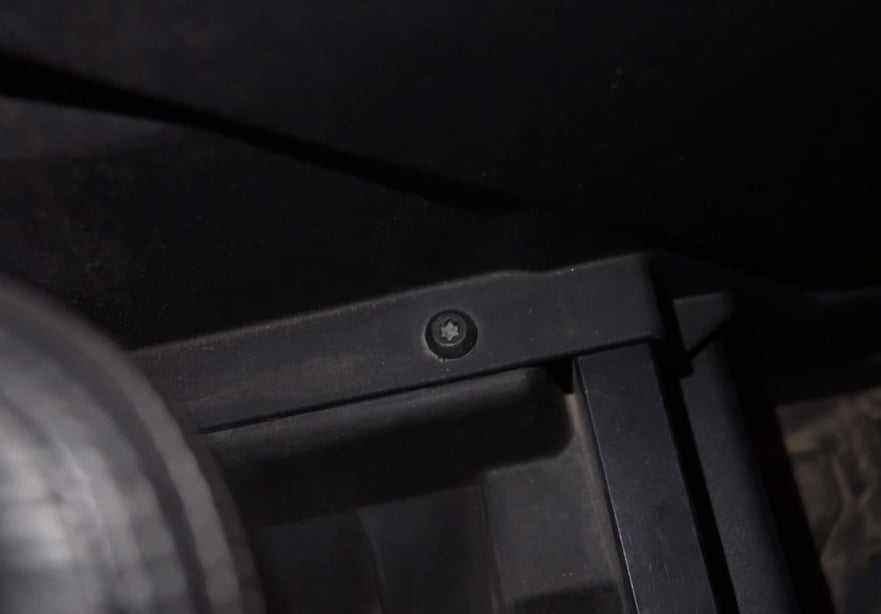
Remove the OEM bolt on the underside of the vehicle next to the suspension column, and install the front Particle Separator bracket with the same bolt.
Tool: T40 Torx
Remove the OEM bolt on the underside of the vehicle next to the suspension column, and install the front Particle Separator bracket with the same bolt.
Tool: T40 Torx
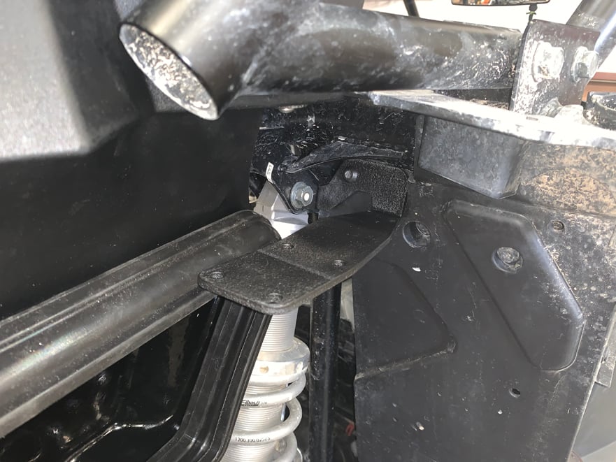
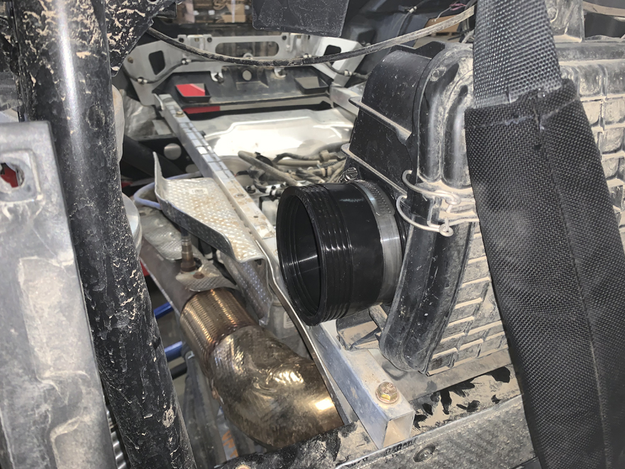
Install the main unit of the Particle Separator using the supplied M6 screws and washers and attaching it to the front and rear Particle Separator brackets. It will need to be pressed into the scoop/seal hard to line up the screws. This ensures a tight seal.
Tool: 4mm Hex key
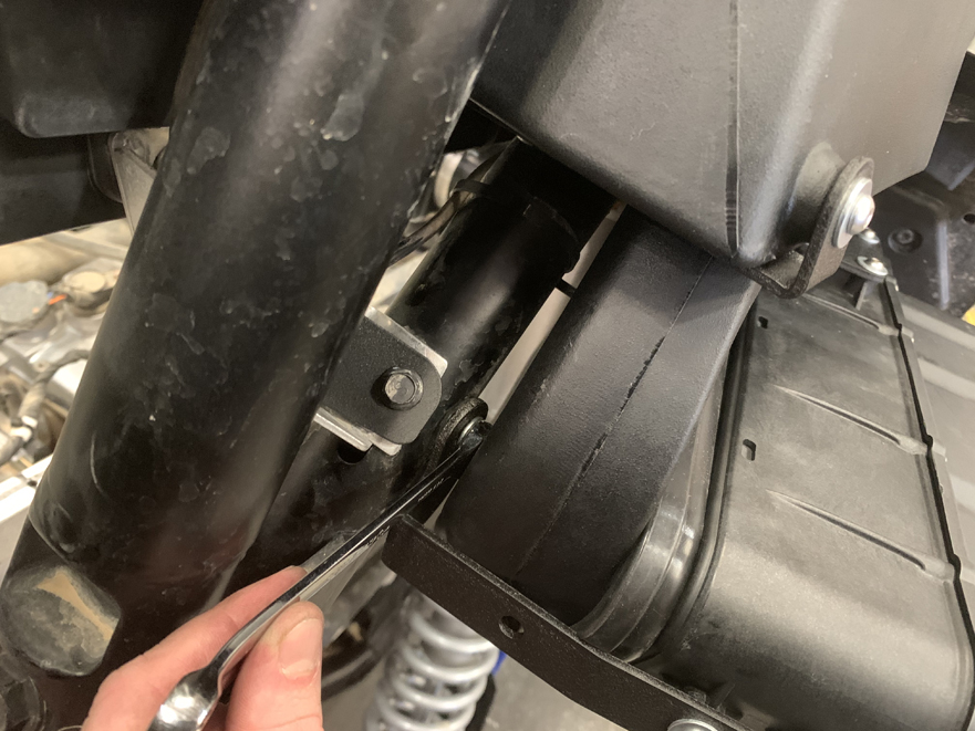
Tighten the rear PS bracket using a wrench
Tool: 10mm Wrench
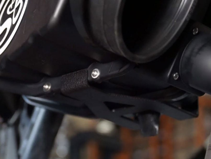
Install the bottom PS bracket to the rear of the scoop by first hand tightening the supplied M6 screws and washer leaving it a bit loose. Then pull the other end of the bracket past the rear of the Particle Separator so it snaps up underneath it pulling it into the scoop seal. Then fully tighten the screws into the rear of the scoop.
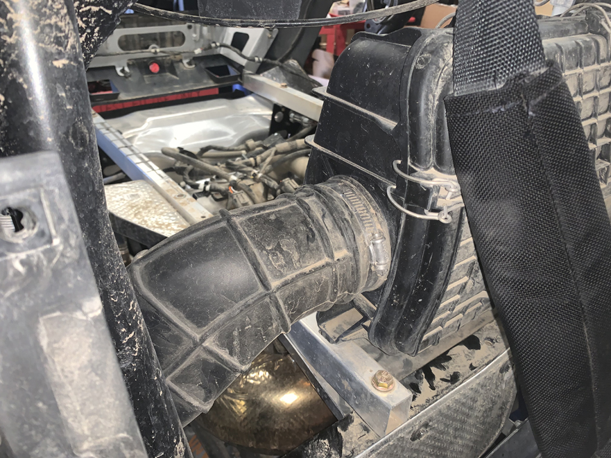
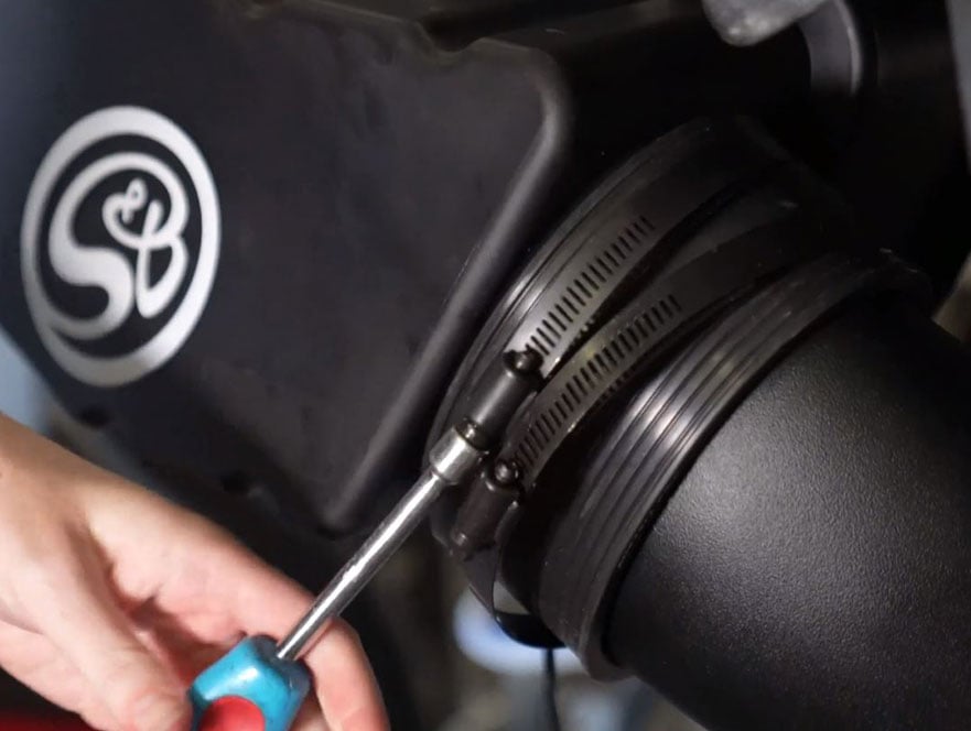
Install the Straight coupler on to the airbox and tighten the supplied hose clamp.
Tool: 5/16” driver
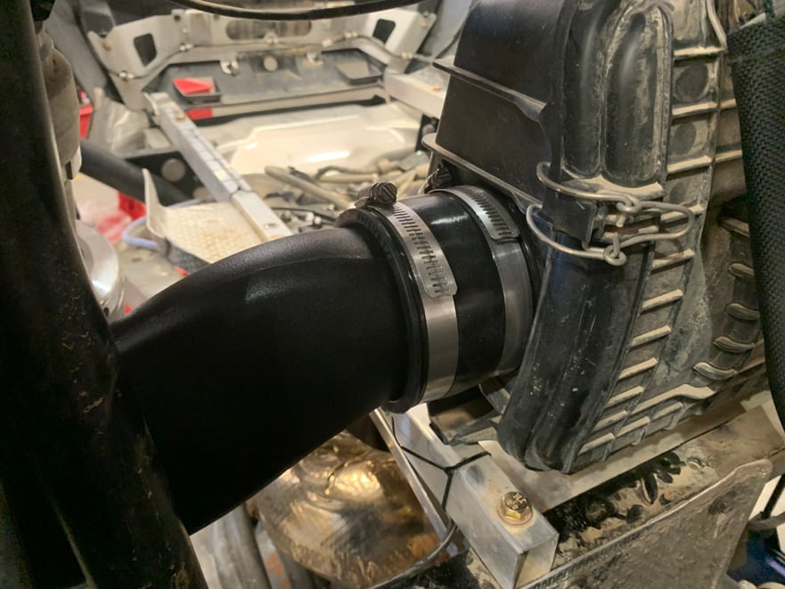
Install the S&B Intake tube and tighten the supplied hose clamps at both ends.
Tool: 5/16” driver
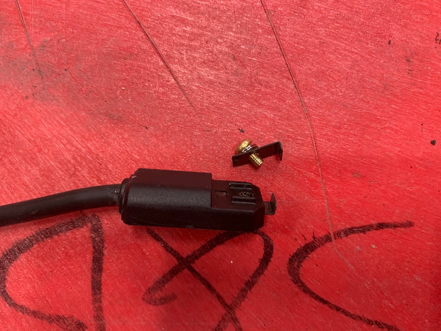
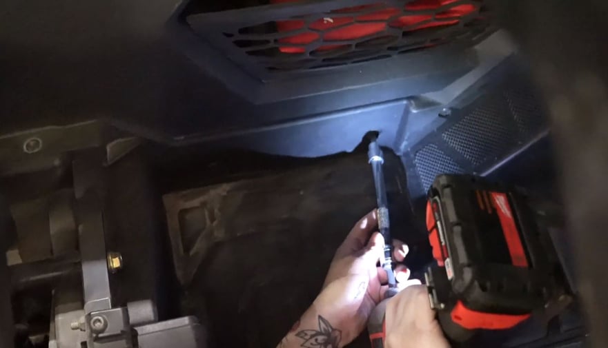
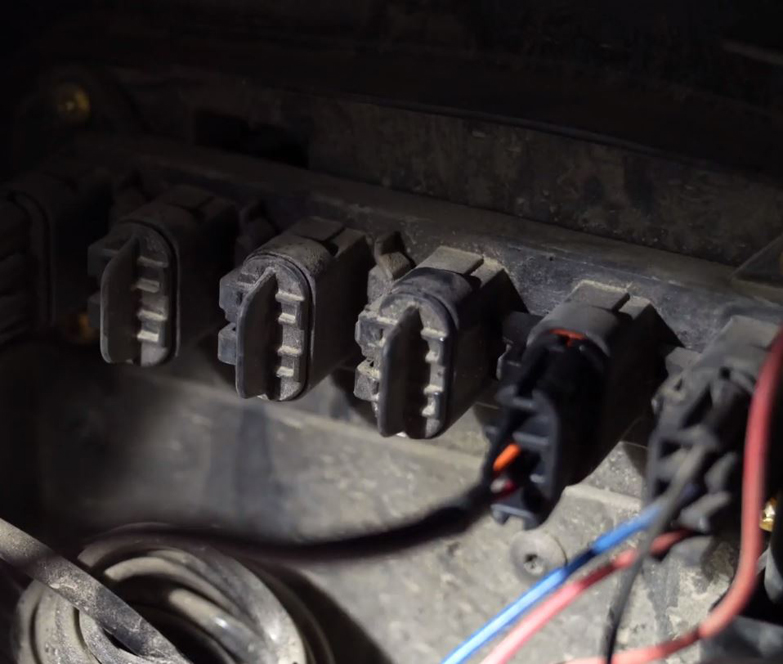
Locate the ignition sensor and remove the top clip piece.
Tool: Phillips screwdriver
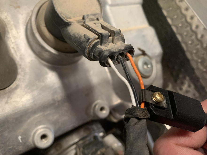
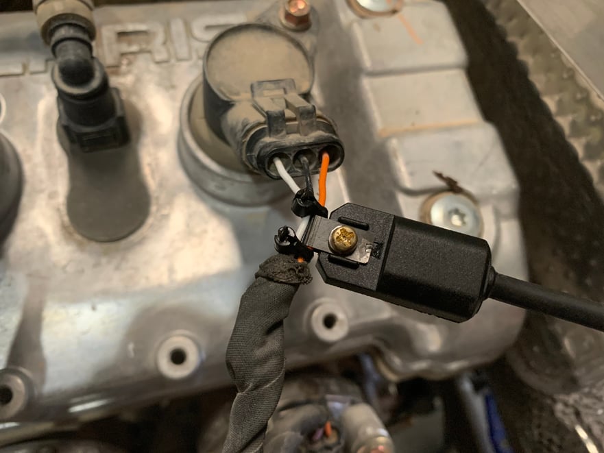
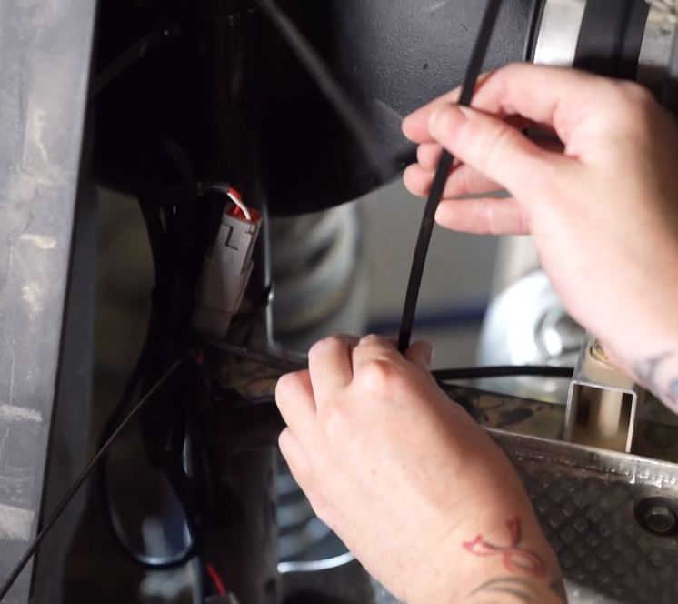
Install the ignition Sensor onto the positive ignition coil wire placing it about 1” away from the connector. Make sure that the top clip piece touches the bottom clip piece on the inside. Use Zip ties on each side of the connector to ensure it does not slide up or down the wire during use.
Tool: Phillips screwdriver
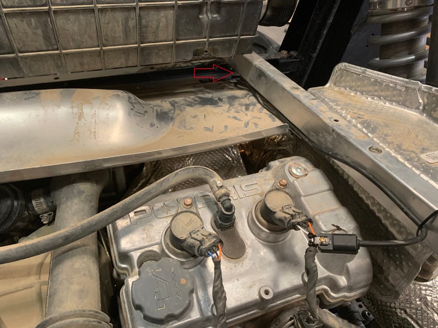
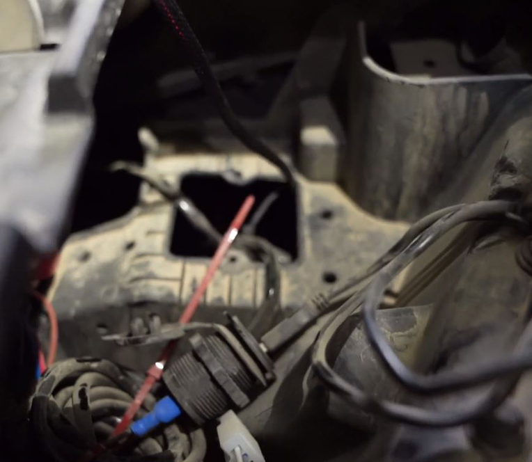
Route the sensor harness towards the front of the vehicle, under the airbox and pass the connector through the opening underneath the frame on the right side. Use zip ties to secure the harness to the frame away from engine components.
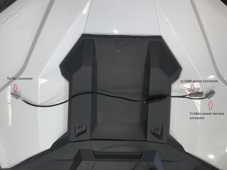
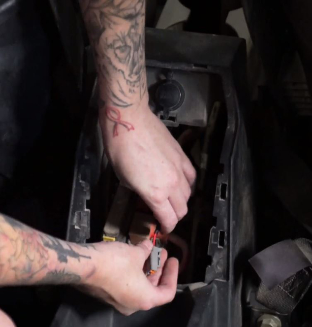
Locate the Y connector harness and familiarize yourself with it using the picture for this step. One side will have a single connector that connects to the scavenge fan from the PS. The other end has two connectors: one square 4 pin connector that connects to the ignition sensor, and one flat 3 pin connector that connects to the main power harness.
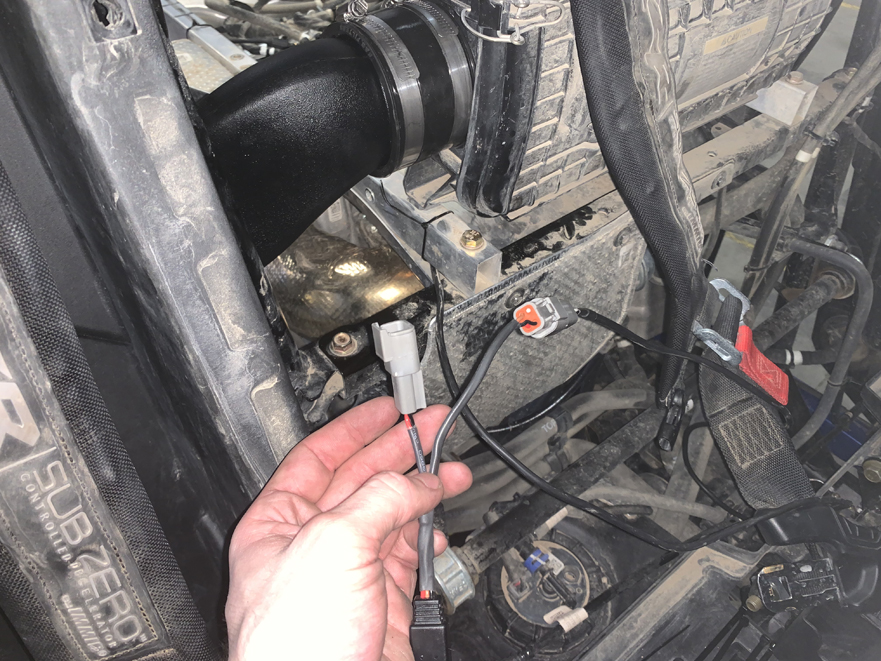
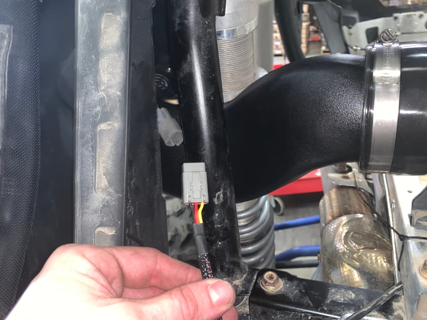
Plug the square 4 pin connector on the Y harness into the connector on the ignition sensor that you pulled through the frame earlier (See another view of routing in this picture).
Connect the single 3 pin connector on the other side of the Y harness into the connector from the Scavenge fan coming from the main Particle Separator unit.
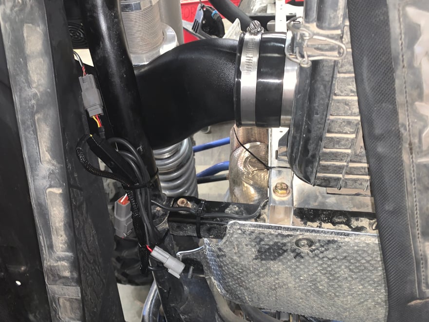
Bundle the remaining length of the Y harness if necessary for your vehicle application, and zip tie it to the chassis as shown with the connector that goes to the main harness pointing down.
For 4-seater applications, fold the back to seats forward and remove the back seat panel by removing the 11 screws and one push pin on the passenger side. Then pull up and remove the panel.
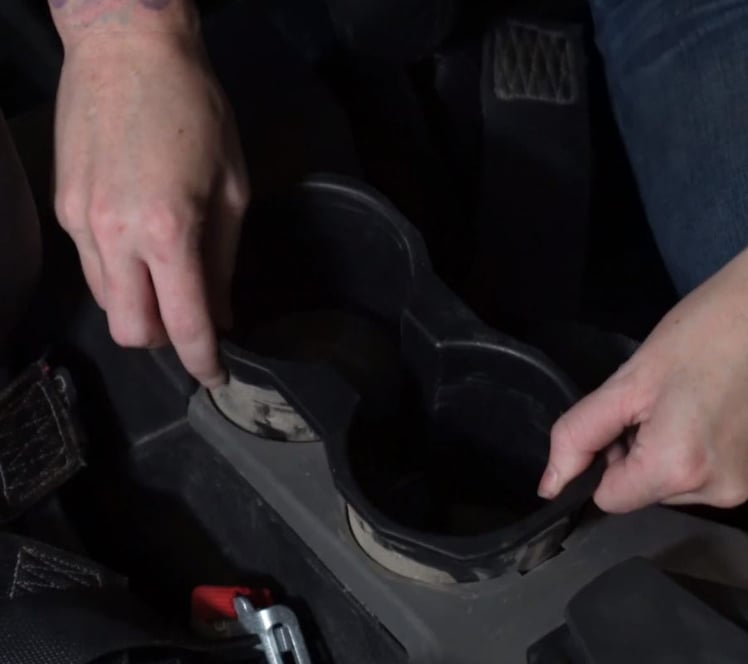
Remove cupholders, both front and rear if applicable, by simply pulling up and out. This will allow for easier wire harness routing.
For 4-seater applications, remove the back center console panel by simply pulling out and away.
.jpg?v=1686747280223)
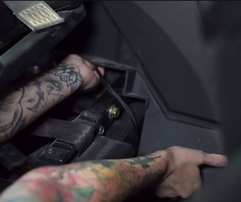
Remove the 6 screws securing the front passenger side center console panel so you are able to pull the bottom forward, but not fully remove. Make sure to remove the ones next the the seat as well.
Remove the front in-dash tray by using a pry tool or screw driver to pop out both sides under the handles, then pull up and out.
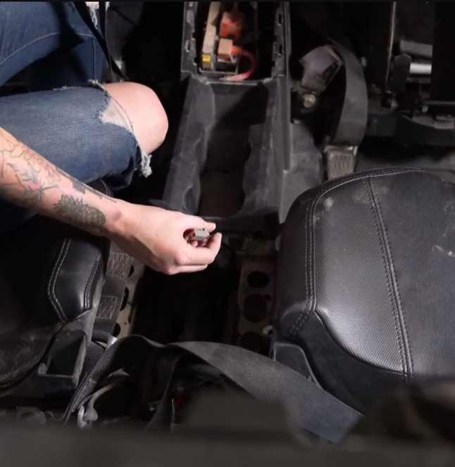
Route the connector end of the main power harness through the hole in the dash down through to the passenger side and pull enough through to route the rest of the harness.
Pull the center console side panel out from the bottom and insert the connector underneath it as shown. You can grab a hold of it from the cupholder opening. Once it is through, push the rest of the harness into the center console under the panel as well.
Pull the center console side panel out from the bottom and insert the connector underneath it as shown. You can grab a hold of it from the cupholder opening. Once it is through, push the rest of the harness into the center console under the panel as well.
For 4-seater, route the harness back through the center console and out where you removed the back seat panel.
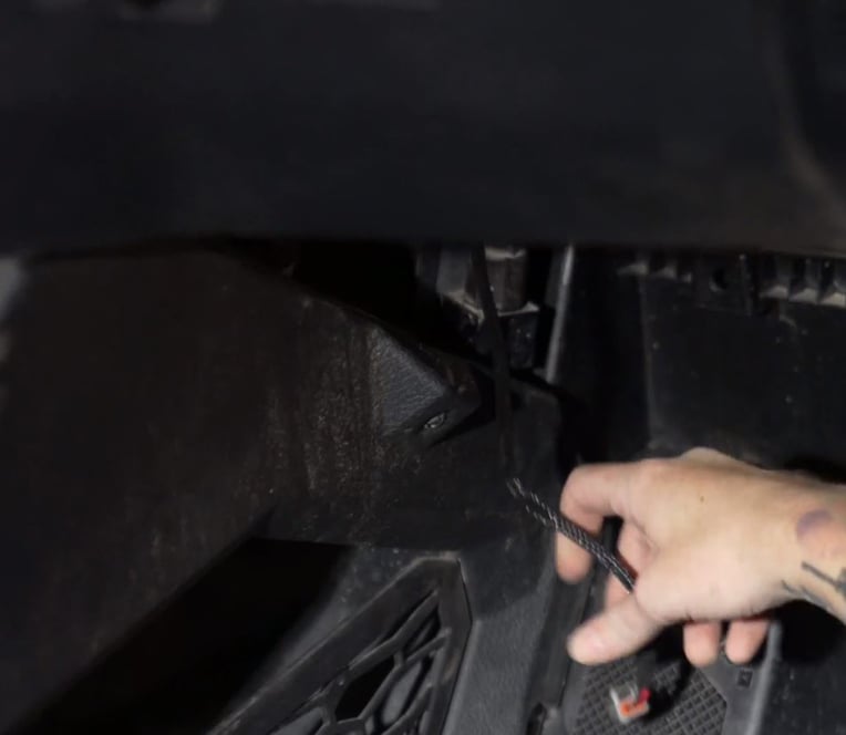
Pull the harness to the back under the frame and sway bar.
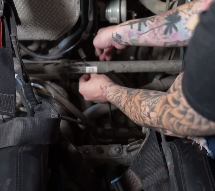
Connect the main harness to the Y-splitter harness end. Use zip ties to secure the bundle you made before as well as any loose harness from the ignition sensor.
Connect the pulse connector to one of the plug-ins in the dash.
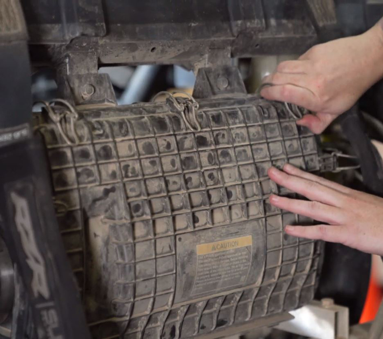
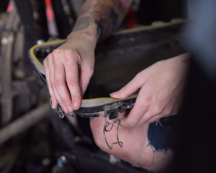
Remove the airbox lid by undoing the latches and pulling off. Remove the current lid seal by simply pulling it out. Install the new airbox lid seal provided by pressing it in to the channel in the lid. Make sure the yellow side is facing up. Reinstall the airbox lid.
Reinstall the cupholders, back center console panel, rear seat panel, and center dash tray.
Secure passenger side panel with screws removed in step 34.
.jpg?v=1686748611116)
Reinstall the rear brake light using the 3 plastic screws from before. Reconnect the power harness to the light.
Tool: T30 Torx
Reinstall the rear body panel assembly with the oem hardware removed before. Remember to pull the rubber seal holding the gas fill cap back into the plastic.
Tools: T40 Torx
Install the bed back onto the vehicle and screw in the 4 bolts to secure it to the frame. The install is now complete. Check everything over to make sure all connections are tight, and all electrical plugs are connected properly.
You have now completed the installation for your new Particle Separator. To ensure that everything is installed correctly and there are no problems with any part of the electrical system, we need to run a test to verify the function of the whisper quiet fan technology system.
Test the particle separator with these steps:
Turn the ignition to the key on position. The fans on the particle separator should be at 20% speed and should barely be audible.
Turn the ignition on. The fans should be at 50% speed and barely be audible over the engine idle noise.
Rev the engine to a constant 3000 rpm for 5 seconds and then take your foot off of the gas. The fans should build to and stay at max speed during the 5 seconds, and decelerate back to 50% speed 2 seconds after you let your foot off of the gas.
If your particle behaves as these tests describe, the installation is complete. If the separator does not act as described, please watch our electrical system troubleshooting video to determine the cause of the misbehavior.