BEFORE YOU BEGIN
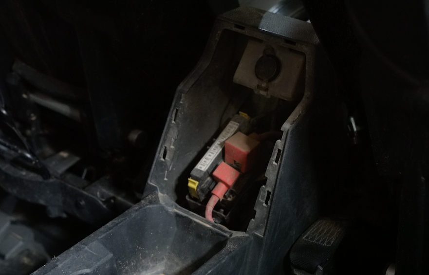
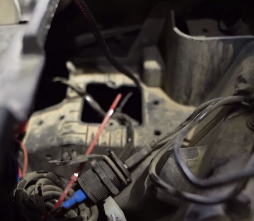
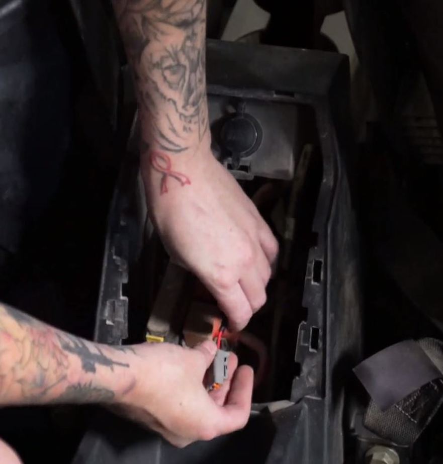
This installation requires the use of a powered electrical busbar found underneath the hood of the vehicle. The provided Wire Harness (17) is designed to work with these factory-installed electrical posts on the busbar and has the length of wire necessary to power the Particle Separator's scavenge fan anywhere on the vehicle. If the busbar in your vehicle is not connected to the vehicle's battery do not begin the installation of the Particle Separator. You will need to install both a power and a ground cable from the vehicle's battery to the busbar. Although not required, Polaris offers a busbar harness kit with complete instructions about how to do this.