Step 1
Remove the 4 screws securing the bed to the vehicle. Lift it up and out, twisting to get it around the vehicle’s side covers.
THIS EQUIPMENT SHOULD BE INSTALLED, ADJUSTED, AND SERVICED BY PERSONNEL FAMILIAR WITH THE CONSTRUCTION AND OPERATION OF THIS TYPE OF EQUIPMENT AND THE HAZARDS INVOLVED. FAILURE TO OBSERVE THIS PRECAUTION COULD RESULT IN SEVERE INJURY. READ THIS MANUAL THOROUGHLY AND MAKE SURE YOU UNDERSTAND THE PROCEDURES BEFORE YOU ATTEMPT TO OPERATE THIS EQUIPMENT. THE PURPOSE OF THIS MANUAL IS TO PROVIDE YOU WITH INFORMATION NECESSARY TO SAFELY OPERATE, MAINTAIN, AND TROUBLESHOOT THIS EQUIPMENT. DO NOT USE THIS EQUIPMENT FOR ANY REASON OTHER THAN ITS INTENDED PURPOSE. FAILURE TO FOLLOW THESE INSTRUCTIONS WILL VOID ANY WARRANTY. KEEP THIS MANUAL FOR FUTURE REFERENCE. THE INFORMATION CONTAINED IN THIS MANUAL IS SUBJECT TO CHANGE WITHOUT NOTICE.
Product will intake and expel both air and loose materials with high force and velocity.
• Install the product on the roll cage, so air inlet is not blocked.
• Do not place face, hair, extremities, clothing, or other loose material in front of air inlet or outlet during use.
• Install product securely to roll cage and avoid placing hair, extremities, clothing, or other loose material in front of air inlet during use.
Moving parts are sharp and could cause personal injury.
• Keep fan safety guard and exhaust cover in place while operating and after service.
• Disconnect the product from the power source before servicing.
Scavenge Fan is designed for use in conjunction with an UTV’s operating manual, and state and federal law.
• Keep your seat belt fastened and wear a helmet while operating the vehicle.
Risk of electric shock!
• Improper installation, maintenance or operation could cause serious injury or property damage.
Note: Approximate Install Time: 2 Hr 30 Mins.
Remove the 4 screws securing the bed to the vehicle. Lift it up and out, twisting to get it around the vehicle’s side covers.
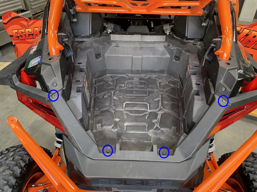
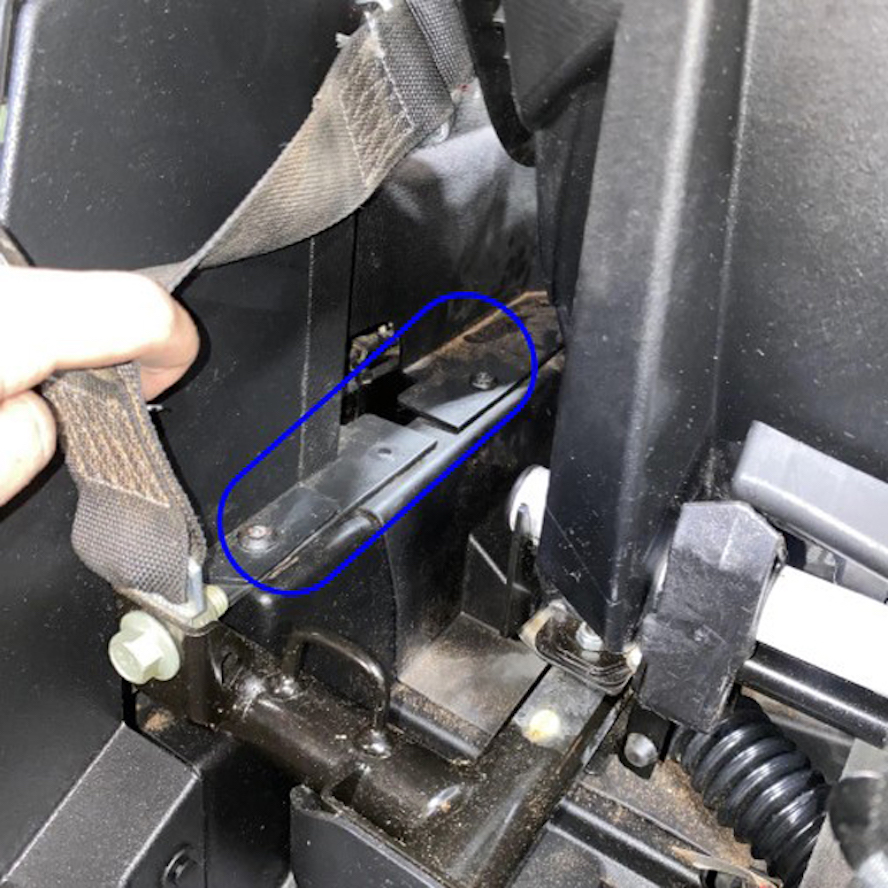
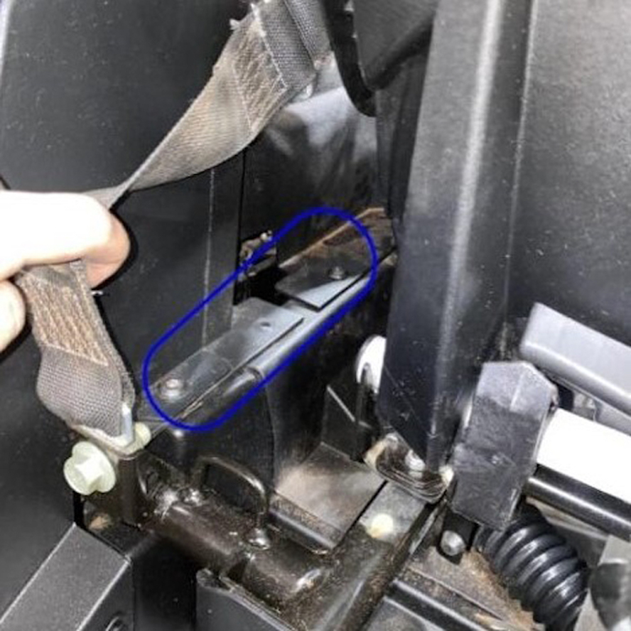
Remove the bolts and push in rivets connecting the rear driver side panel to the rest of the vehicle.
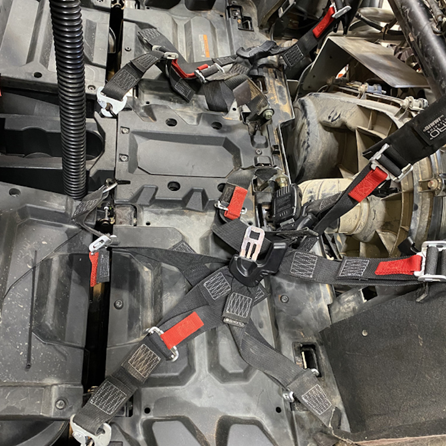
Release the back of the seats (rear if 4 seater) by pressing the release button near the headrest and pull the seats up and out.
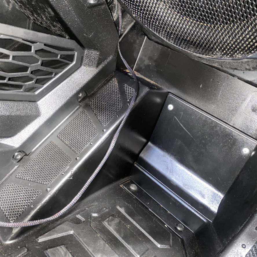
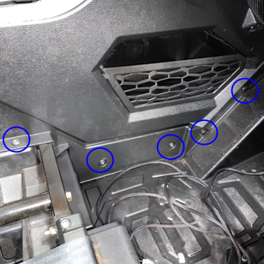
Remove the remaining screws securing the rear driver side body panel to the vehicle from the inside of the vehicle.
Note: Some fasteners and snap-ins vary based on model year.
Pull the side panel assembly off of the vehicle.
Remove the rear panel panel behind the removed seats by turning the quarter turn fasteners.
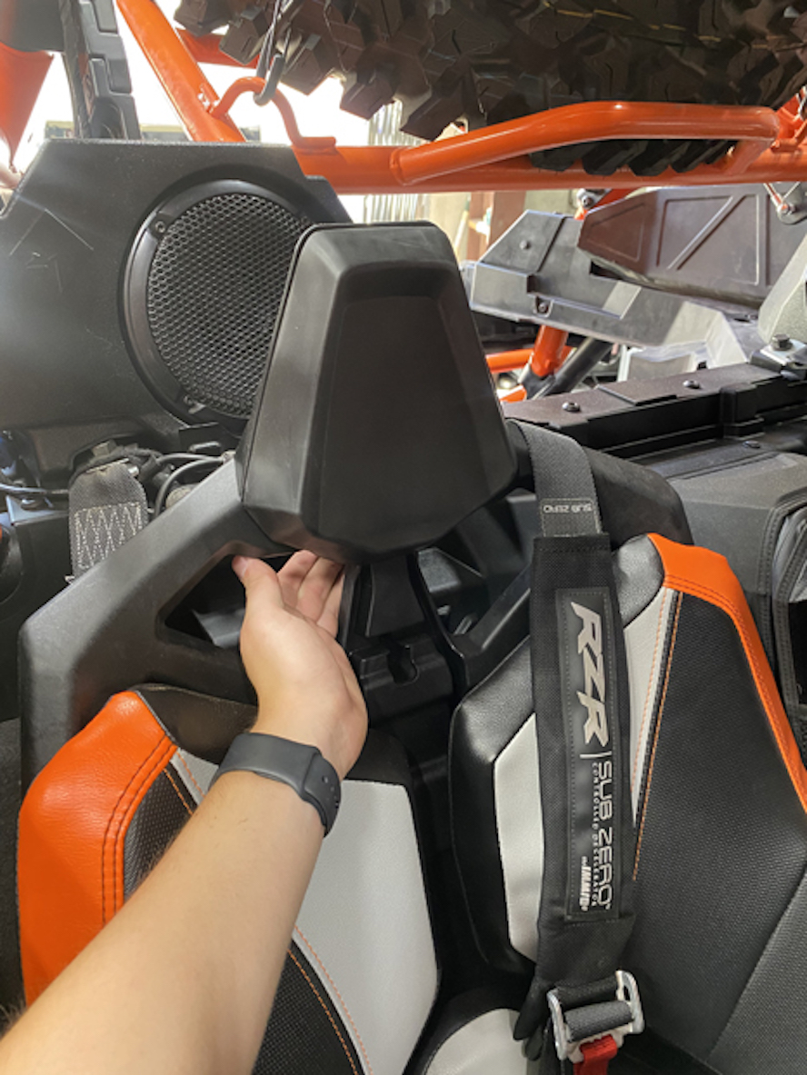
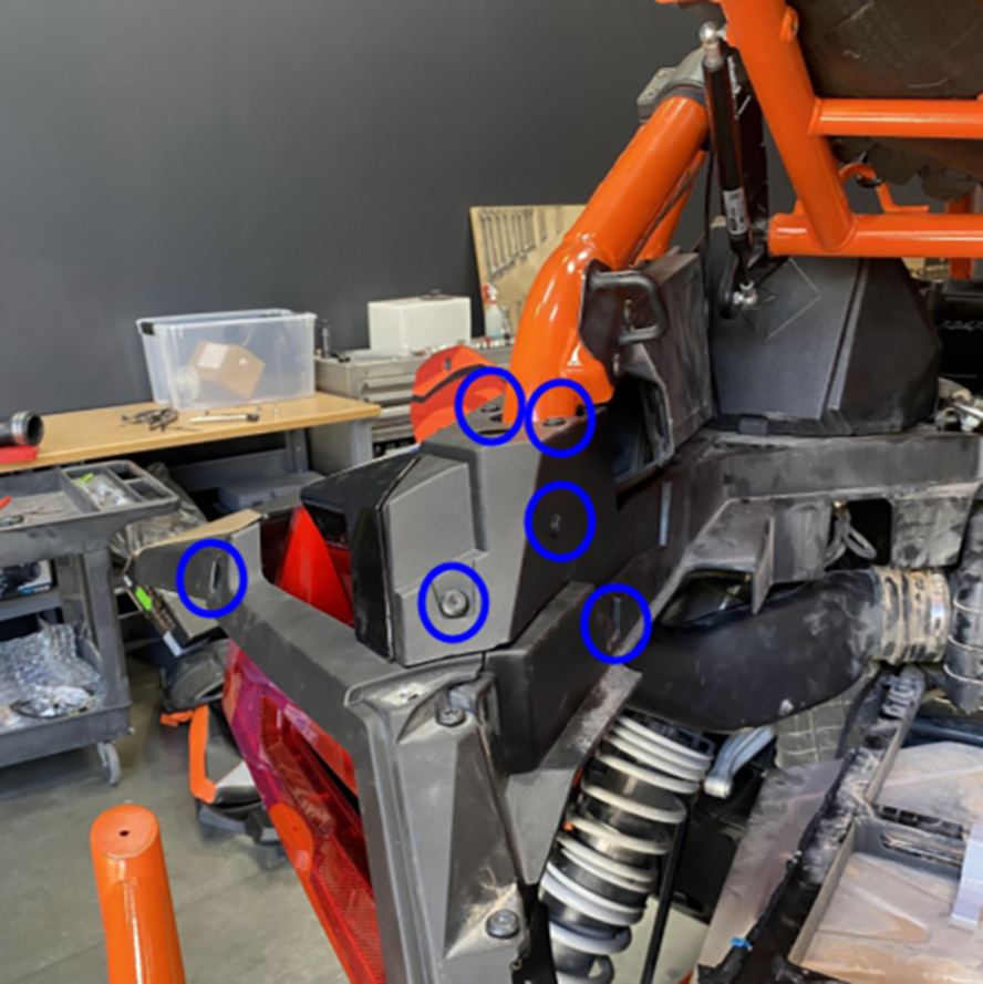
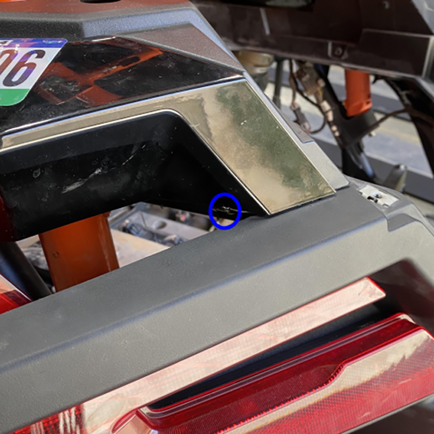
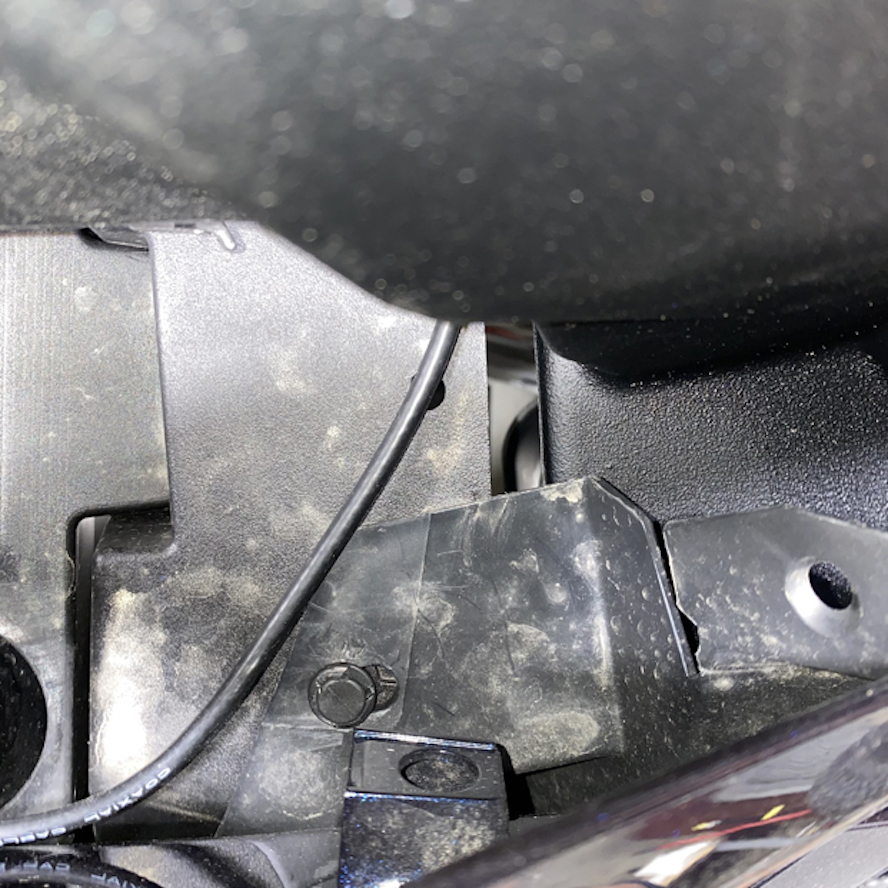
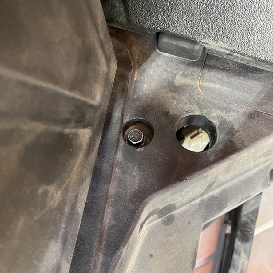
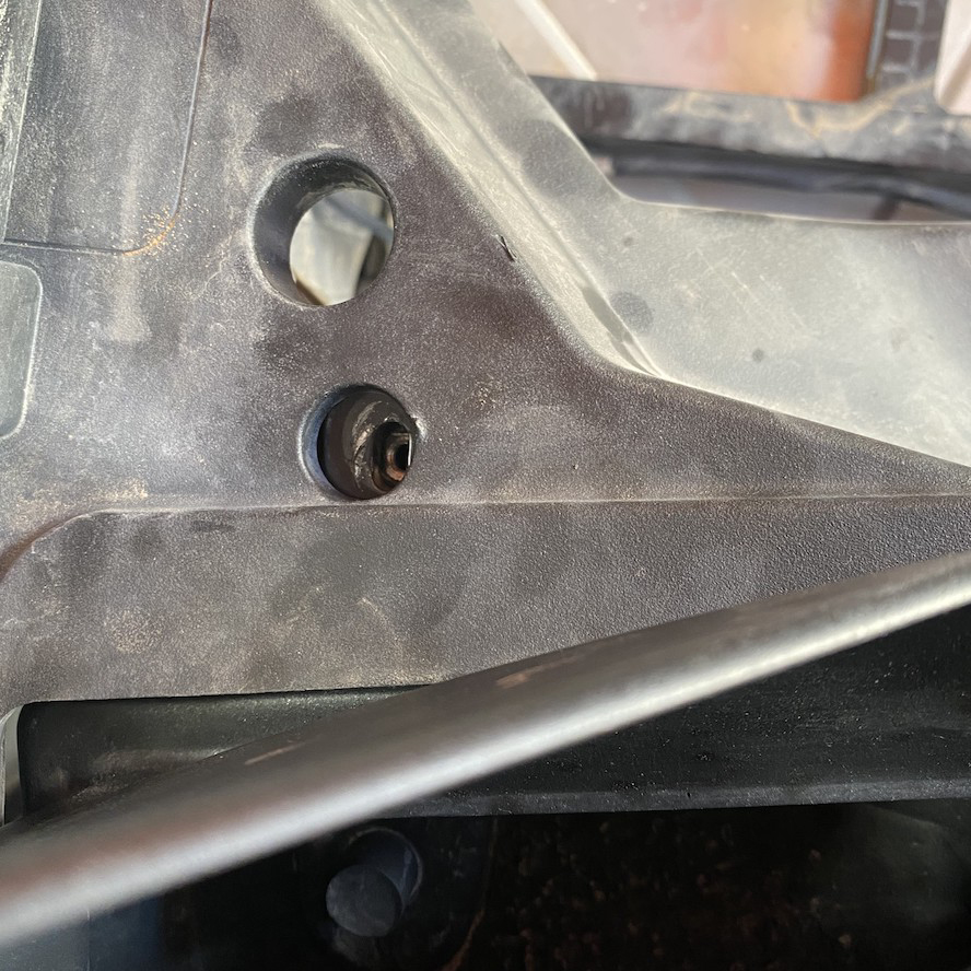
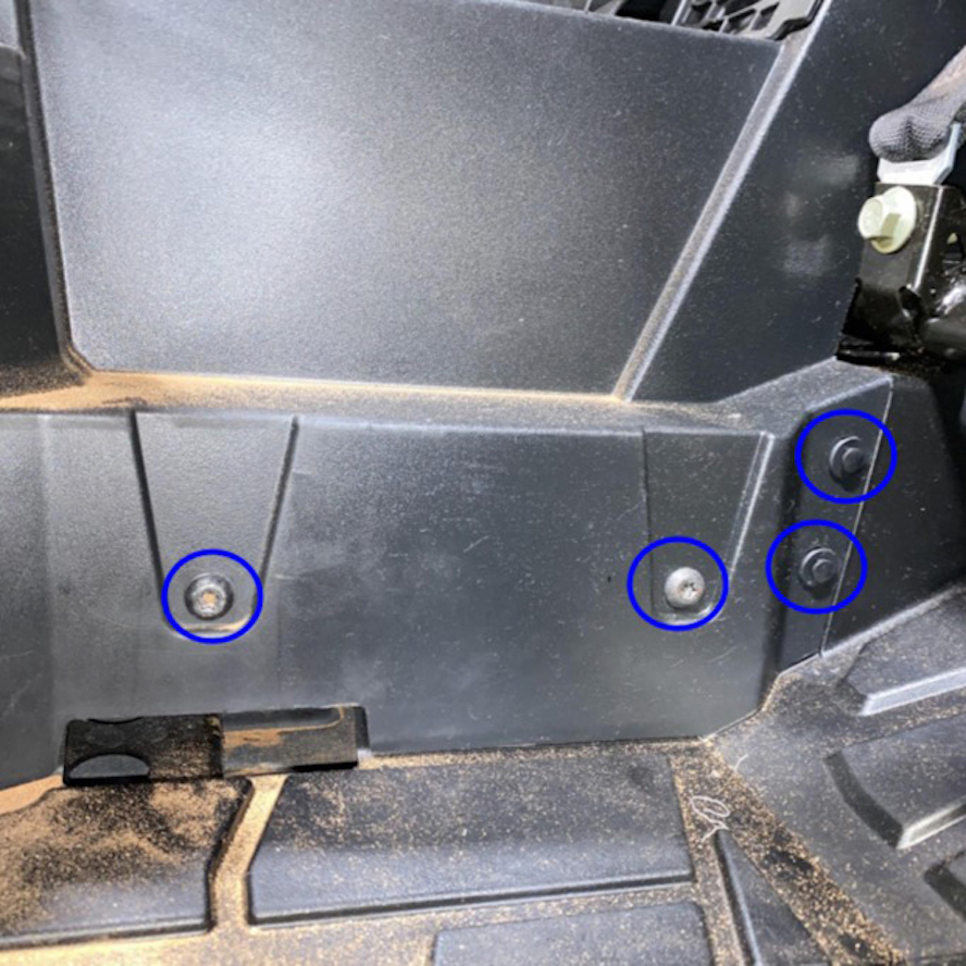
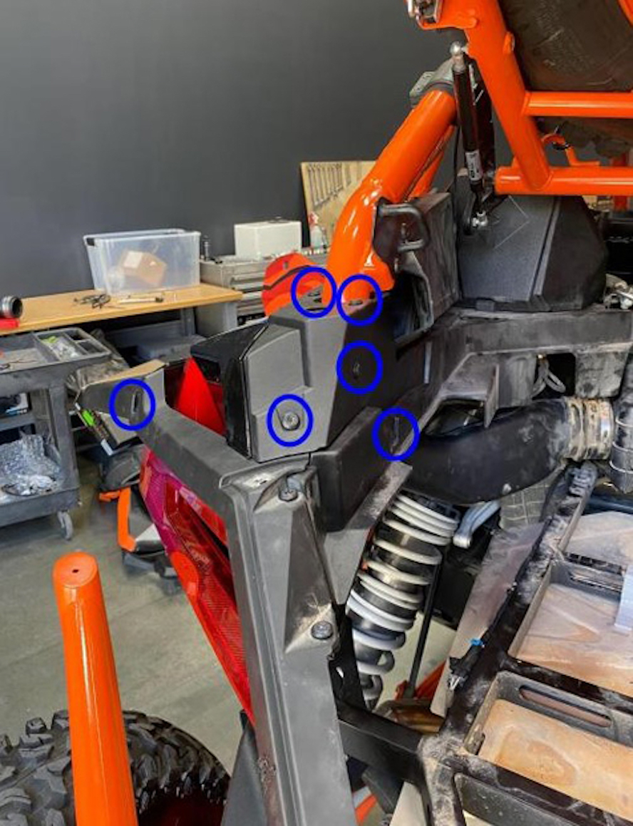
Remove the two screws that secure the stock side cover to the frame.
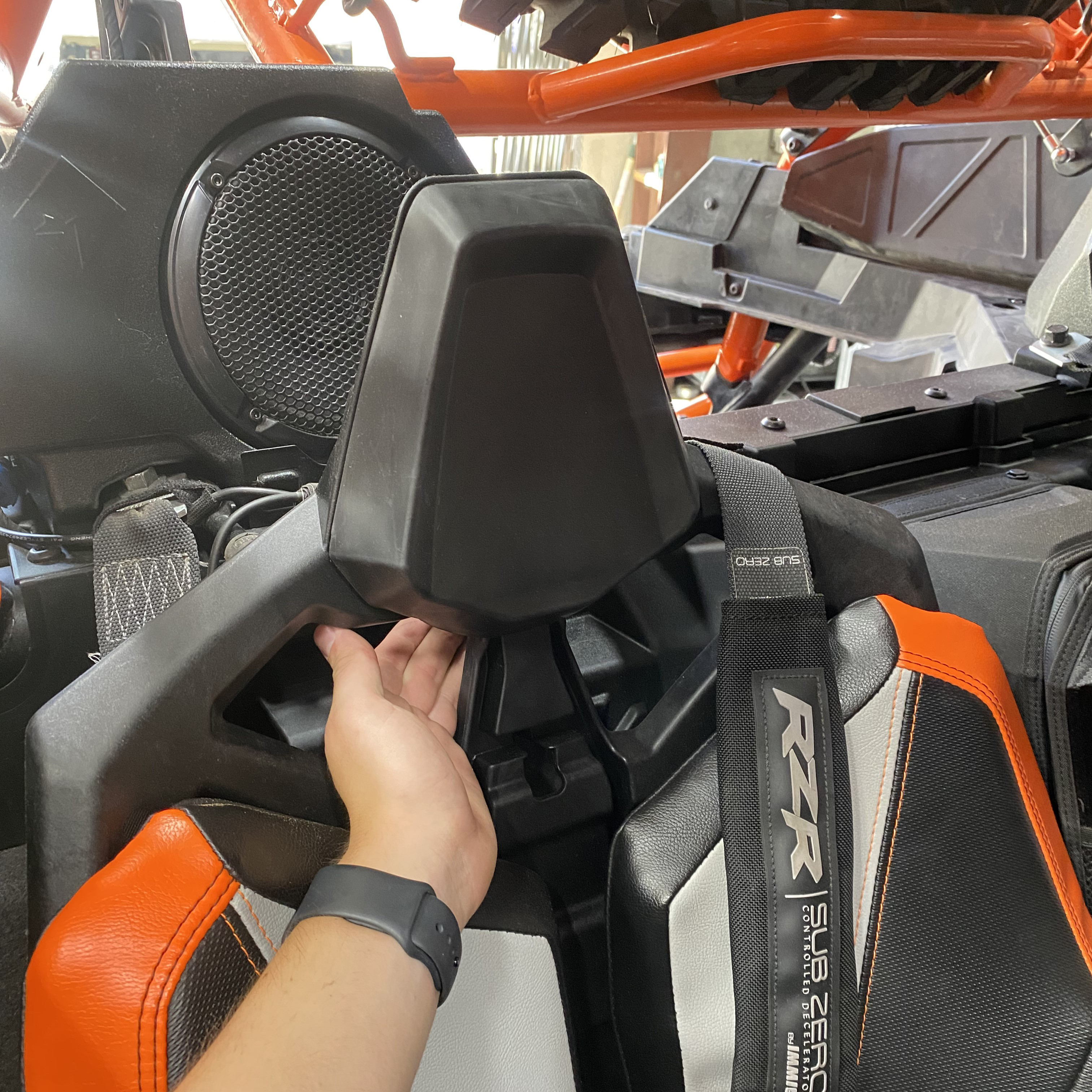
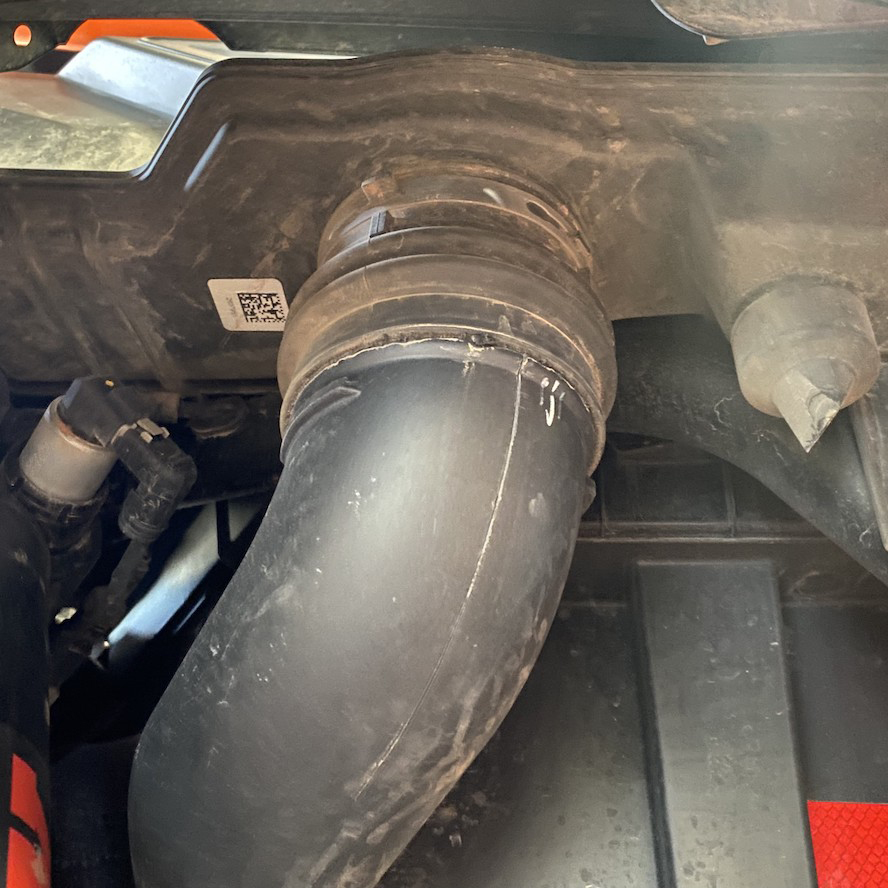
Loosen the hose clamp on the tube connected to the bottom of the side cover and remove the side cover from the vehicle while leaving the other end of the tube attached.
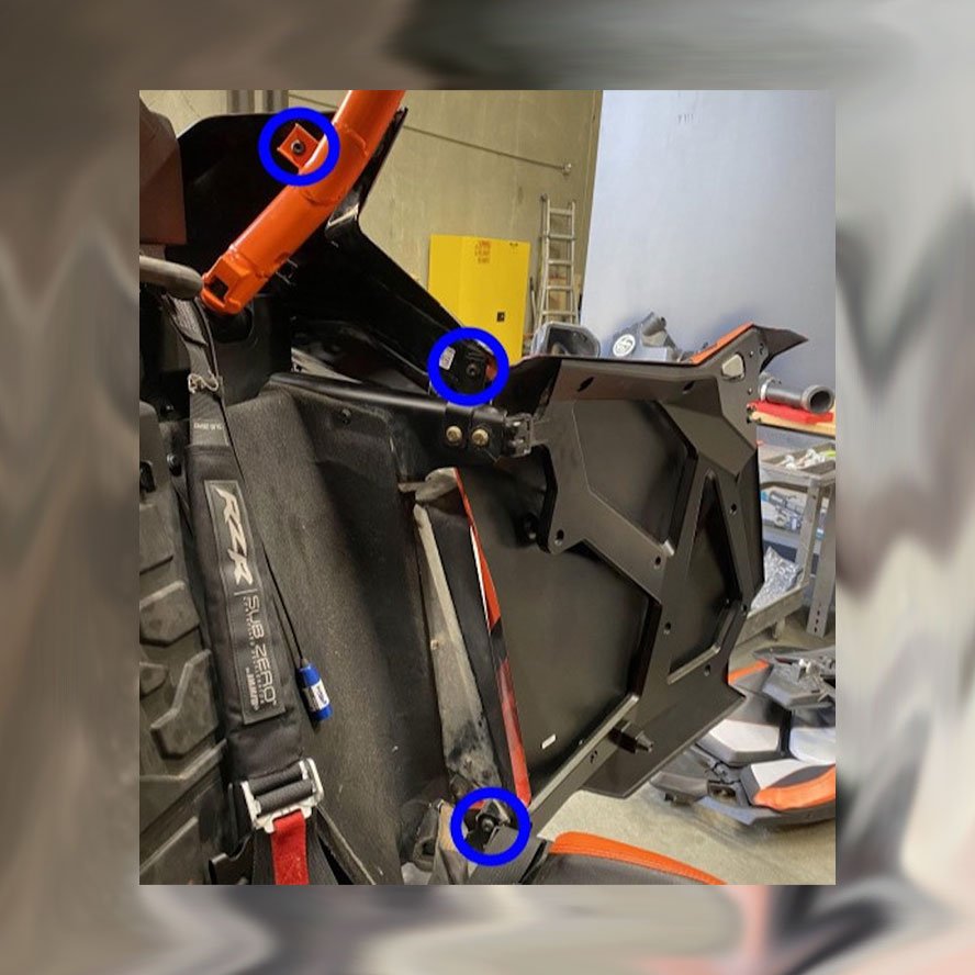
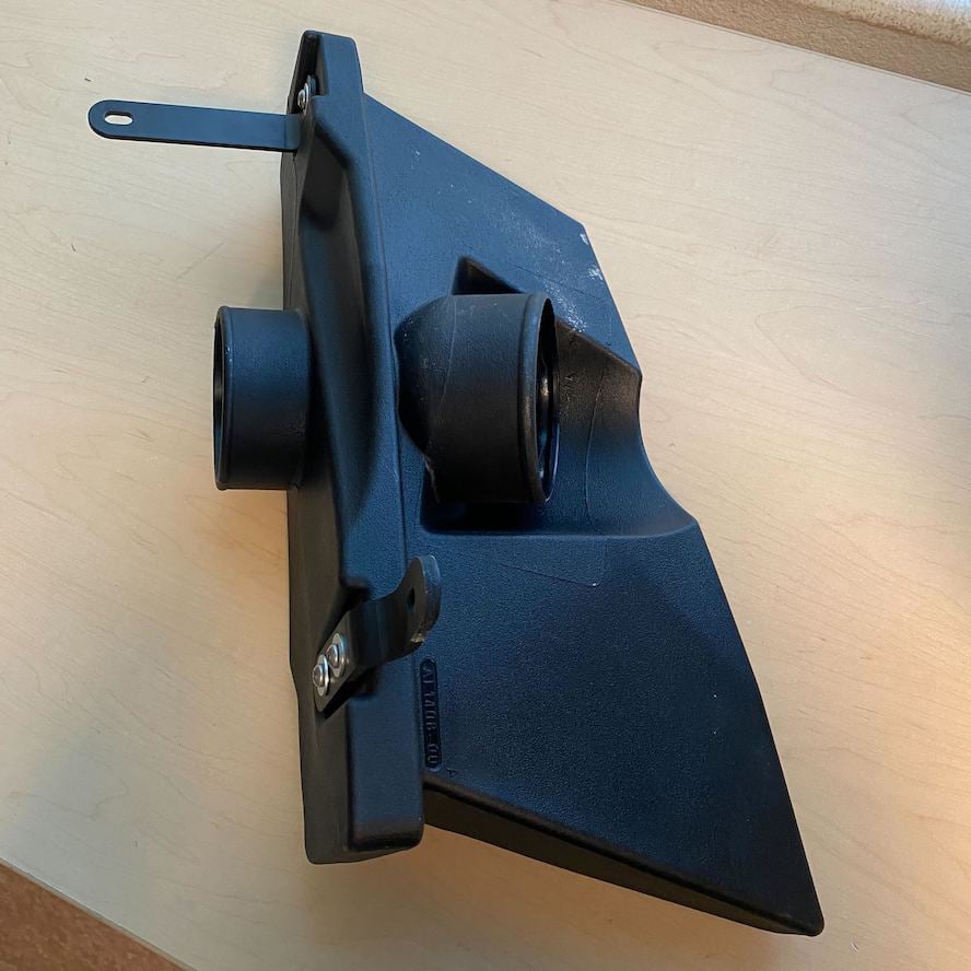
Install the brackets supplied with the M6 Screws and washer on the S&B Side Cover as shown and fully tighten.
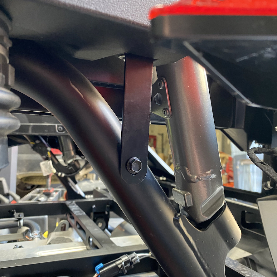
Install the S&B side cover on the vehicle, putting the bent bracket on the side cover between the frame and panel (pictures A and B), while letting the stock tube slide over the S&B side cover outlet. Use the stock screws removed in Step 7 to fasten the two brackets to the vehicle and fully tighten.
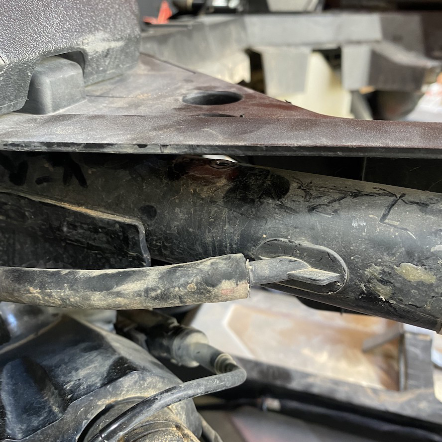
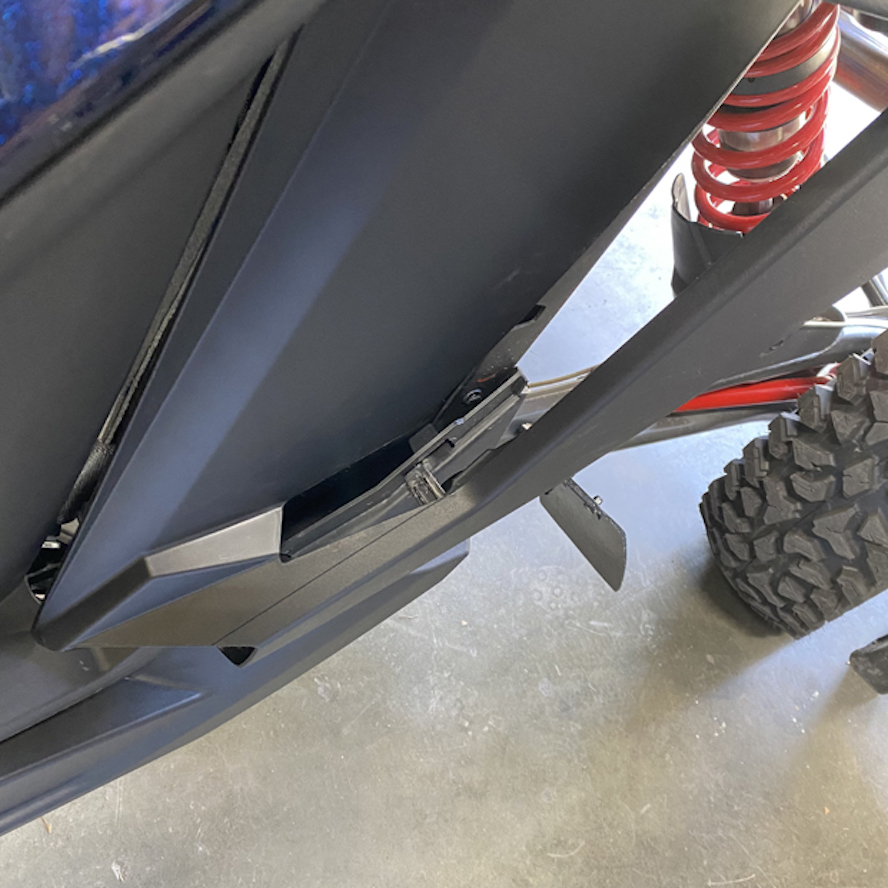
Fully tighten the hose clamp on the tube over the side cover after pushing the tube so it touches the bottom of the side cover.
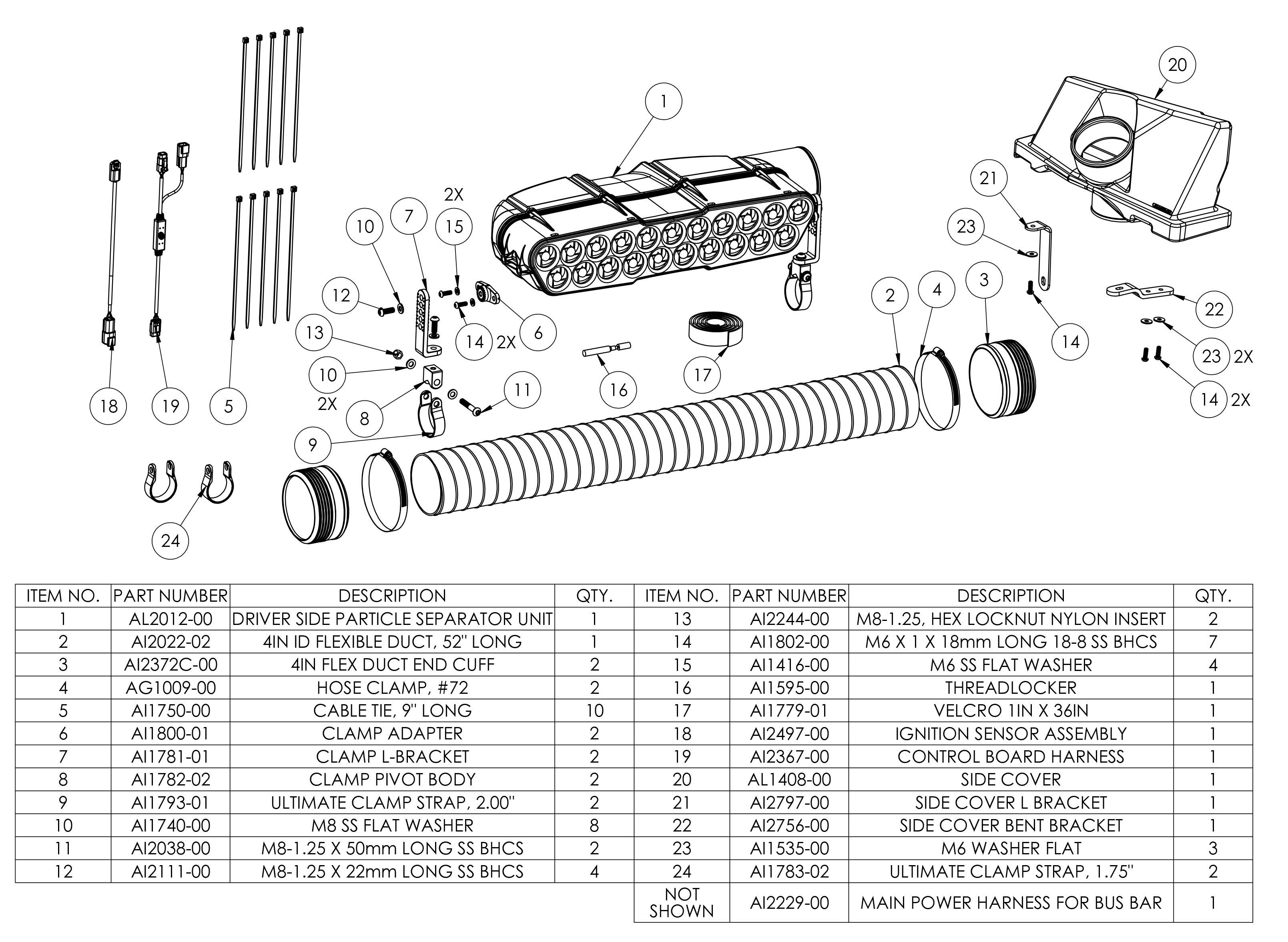
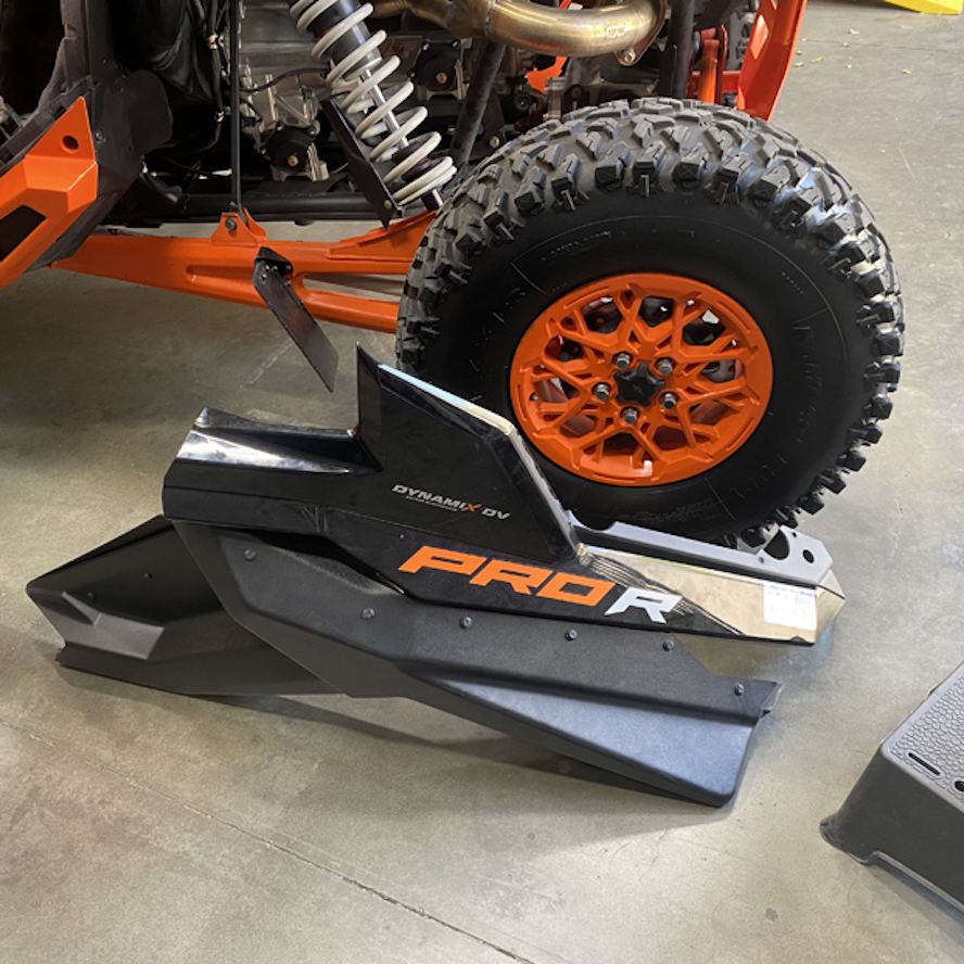
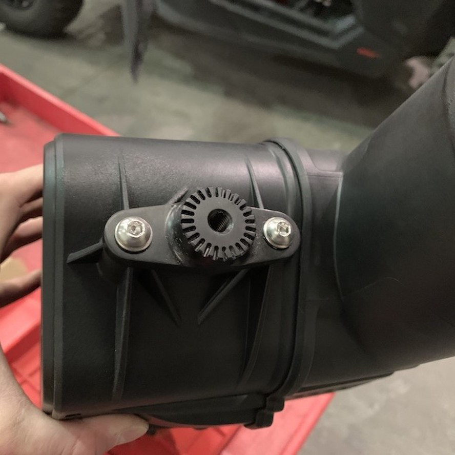
Install the Clamp Adapters on the mounting bosses of the Particle Separator with the supplied M6-1.0 x 18 screws and M6 washers. Apply threadlocker to the screw before tightening. You will do this on both sides of the Particle Separator unit.
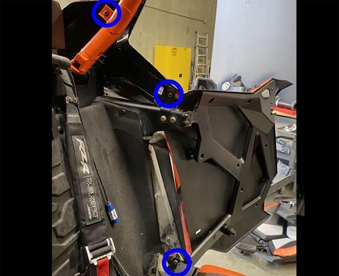
Remove the 4 rearmost bolts securing the roof to the roll cage. This will give you enough clearance to install the particle separator to the upper bar of the roll cage.
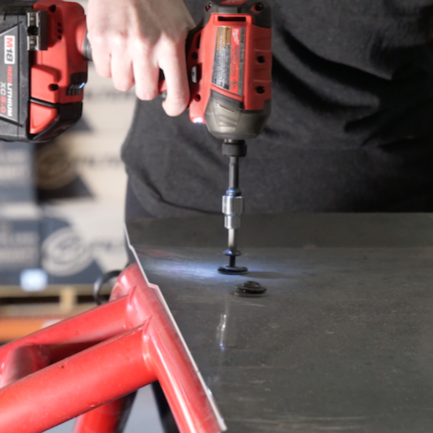
Install the two Clamp Straps (2”) onto the upper bar of the roll cage. Do not pull the ends of the straps open. Loosely wrap some plastic around the roll cage to prevent scratching, and push the straps onto the roll cage until they snap into place.
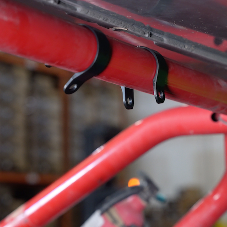
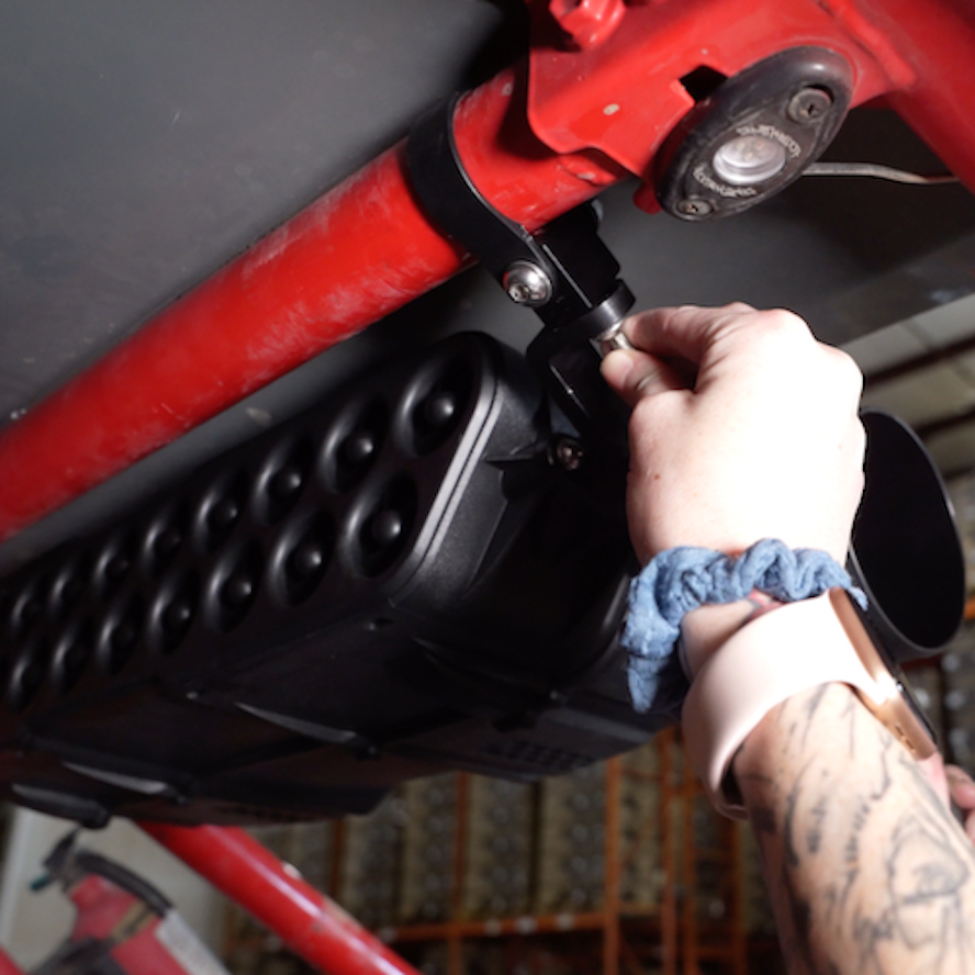
Install the clamp pivot bodies (8) onto the clamp straps with the supplied M8-1.25 x 50 screws (11), M8 washers (10), and M8 locknuts (13). Do not fully tighten the screws and locknuts. Leave the straps loose for final adjustments later in the install.
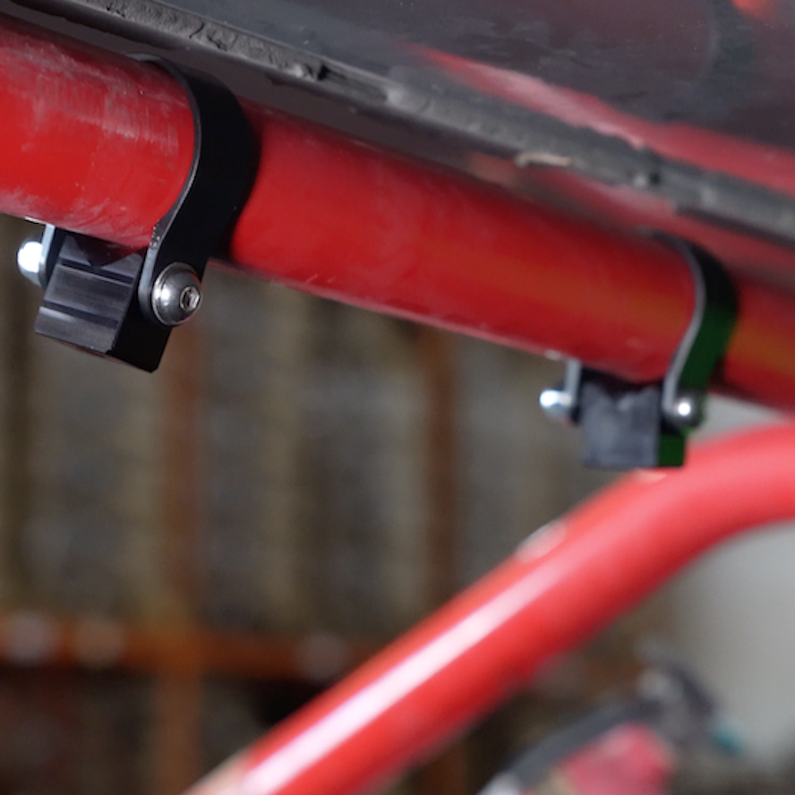
Install the L brackets (7) onto the clamp pivot bodies using the M8-1.25 X 22 screws (12) and M8 washers. Apply threadlocker to the screws before tightening.
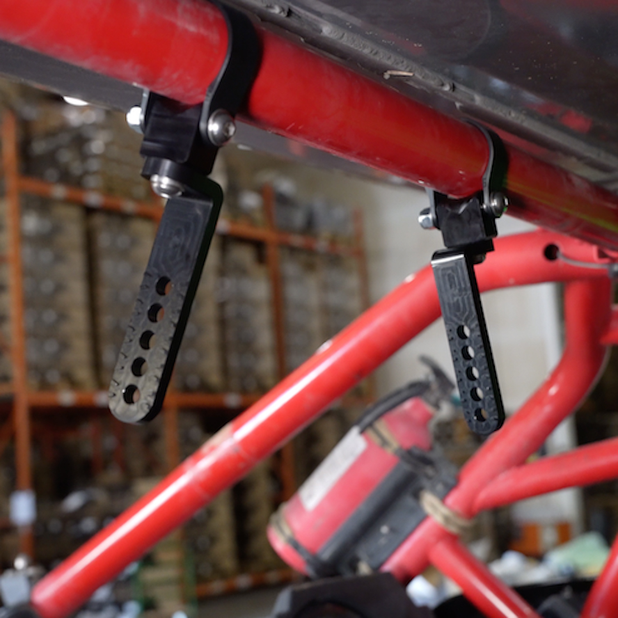
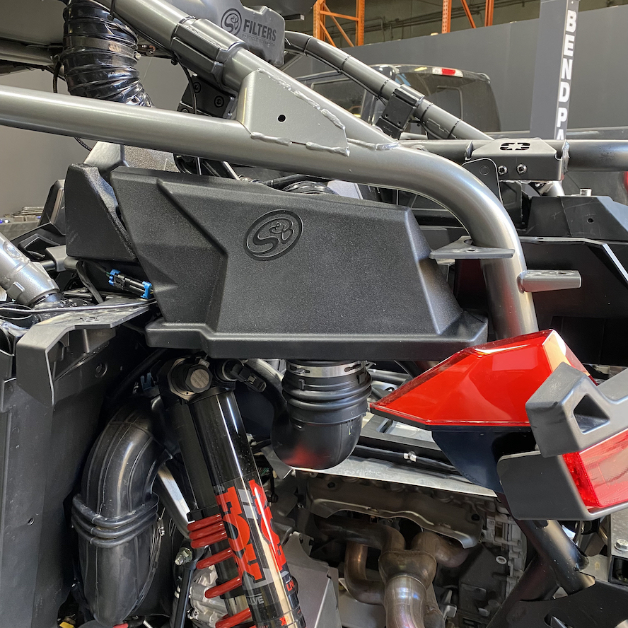
Install the particle separator unit onto the vehicle by fastening the L brackets to the adapters previously installed onto the unit. Determine the proper angle to mount the clamp L-brackets to the clamp adapters based on the desired location for the Particle Separator. Make sure the ribs in the clamp L-brackets are properly seated inside the grooves of the clamp adapters. Do not attempt to rotate these parts once assembled. They are designed to lock into place once seated. Once you're satisfied with the position of the clamp L-brackets, apply threadlocker to the M8-1.25 x 25 screws, install the M8 washers, and tighten. Ensure that the L-brackets on both sides are pointed in the same direction and are aligned with each other.
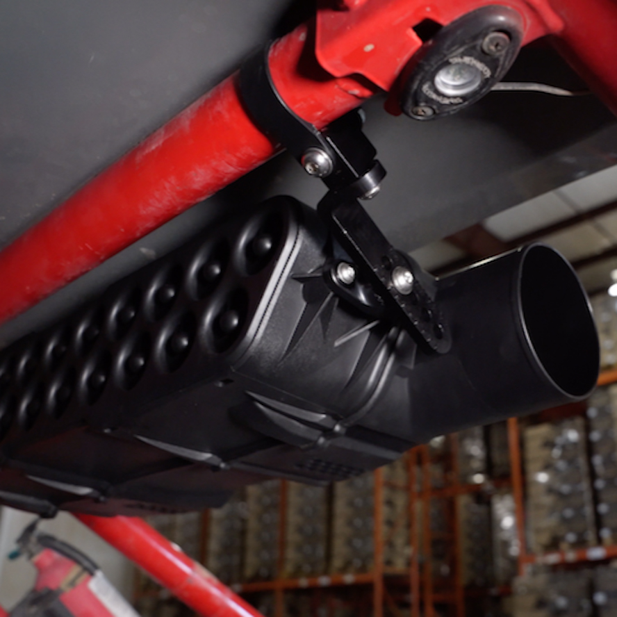
Adjust the position of the particle separator unit so that everything sits as desired. Then tighten all of the screws and nuts associated with the roll cage clamps assembly so that the particle separator is completely fixed and does not move or rotate around the roll cage when shaken.
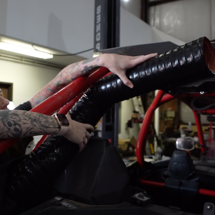
Insert one end of the flexible duct onto the top outlet of the S&B side cover. Do not install the hose clamp #72 or flex duct end cuff yet. Bring the other end up towards the round clean air outlet of the Particle Separator to simulate the desired length of ducting. Note the amount of duct that needs to be cut. We recommend adding at least an extra inch to the length of the duct needed. The duct can always be cut shorter if desired. Remove the duct from the adapter and Particle Separator.
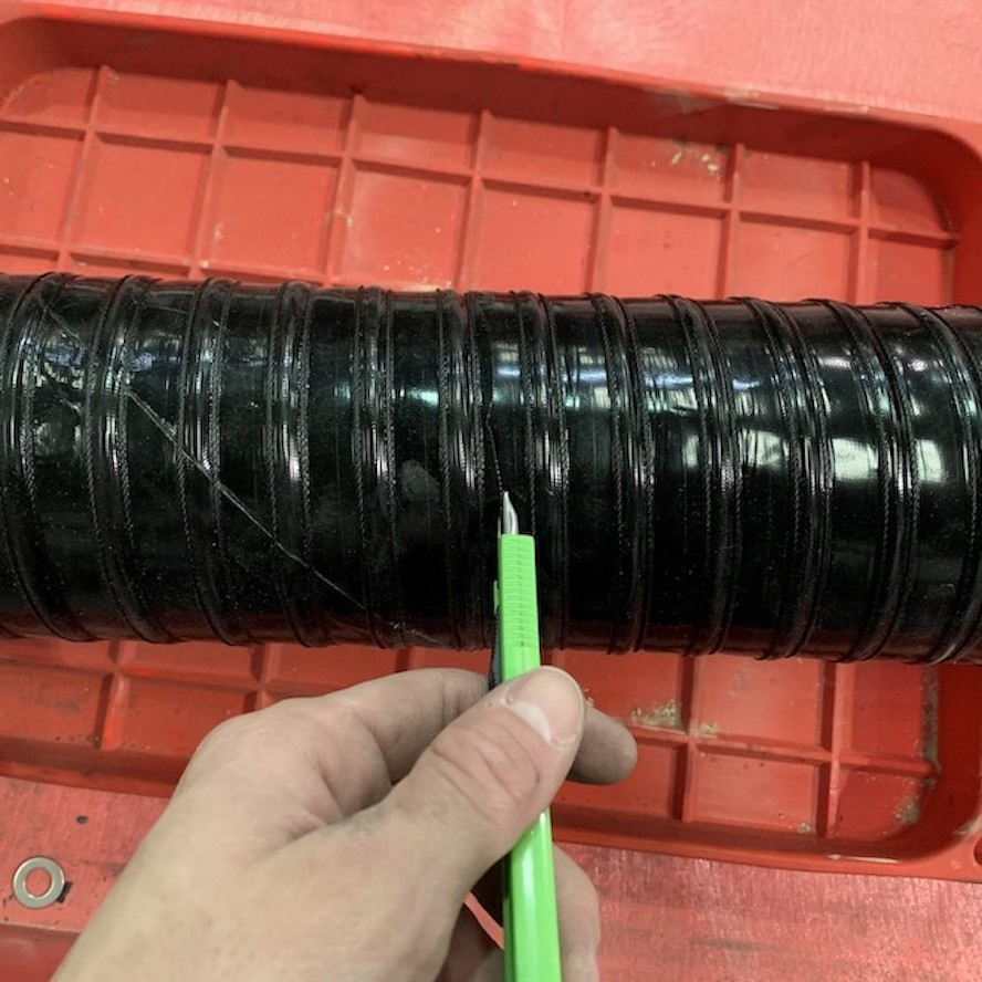
Pierce the flexible duct using a razor blade, centered between the two-wire reinforcements. Cut all the way around, keeping the blade centered between the wire reinforcements the entire length of the cut. Use a mini-bolt or a heavy duty wire cutter to cut through the wire and duct. Use a pair of scissors to finish the cut and to even out any jagged edges.
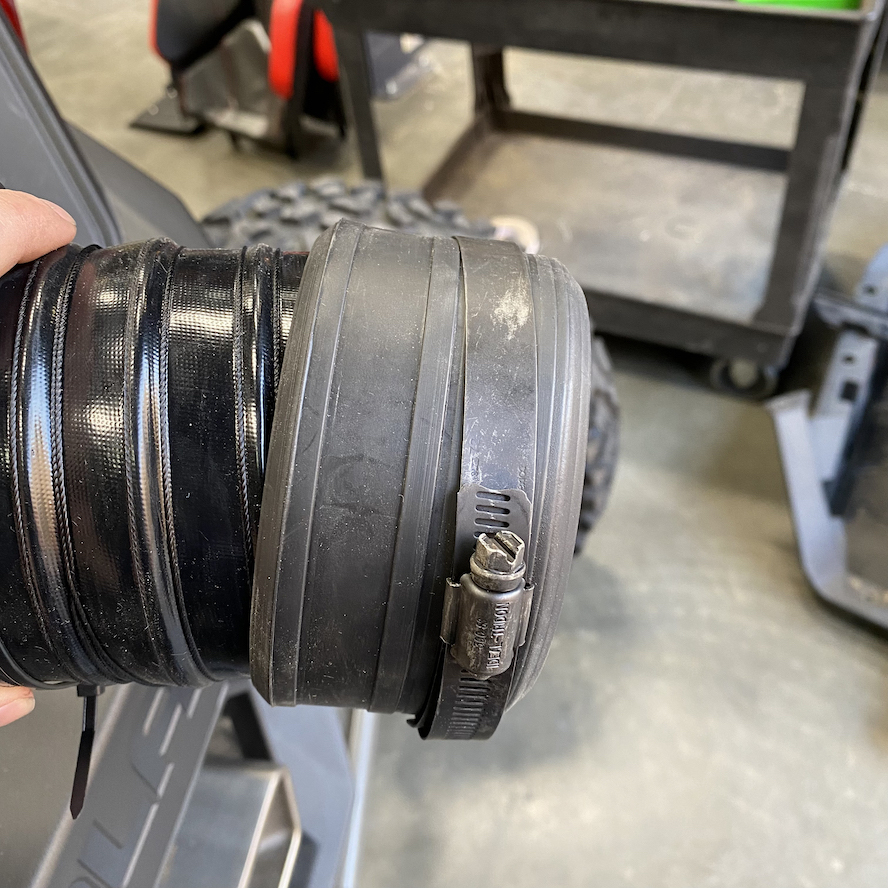
Insert each end of the flexible duct fully into each of the flex duct end cuffs provided. Place the #72 hose clamps around each flex duct end cuffs, making sure that they are seated in the grooves. Leave the hose clamps loose.
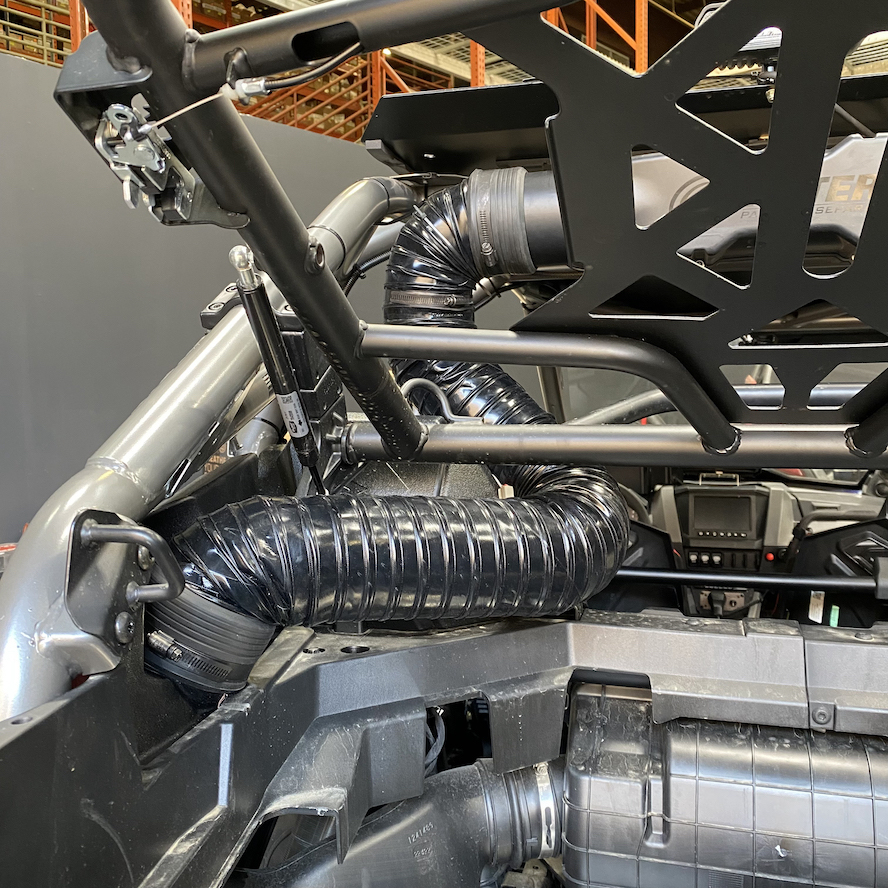
Install one end of the flexible duct onto the S&B side cover and the other end of the flexible duct onto the plenum outlet on the particle separator unit. Tighten each Hose Clamp #72. Make sure the hose clamp is seated in the groove of the Flex Duct End Cuff and check to make sure the duct will not pull off either of the openings. Secure it to the roll cage.
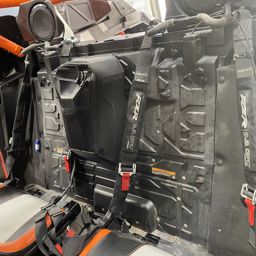
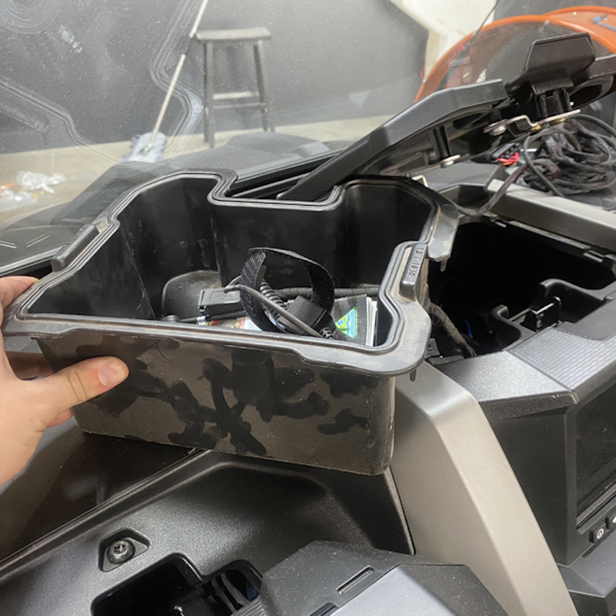
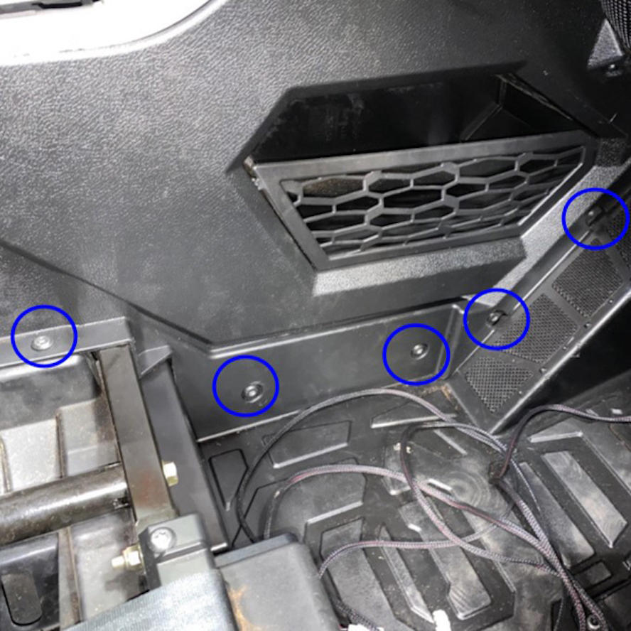
Begin the wire harness installation by opening the center console in the dash and removing the tray by pulling up and out.
Route the connector end of the main power harness through the hole in the dash down to the passenger side foot area, pulling enough to route it to the rear of the vehicle.
Remove all of the screws at the bottom of the center console on the passenger side. Moving the passenger seat can help get the screws in between the center console and the seat.
Remove all of the screws and rivets at the bottom of the center console on the passenger side of the rear for 4 seater applications.
Flip the bottoms of the seats over to remove all of the screws securing the panel under the seats and remove the panel.
You can tuck the wire in at the front passenger foot area while leaving the connector end free near this hole.
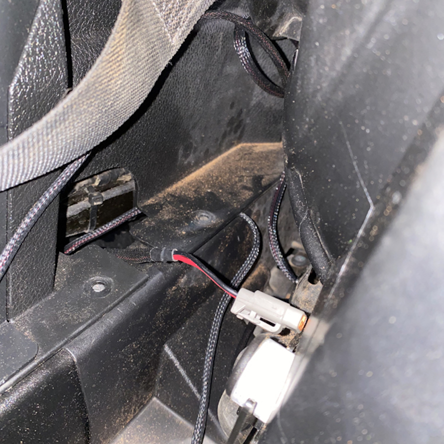
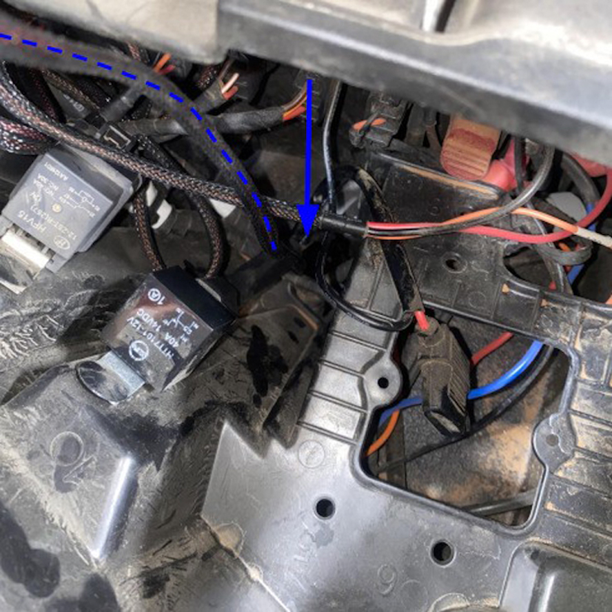
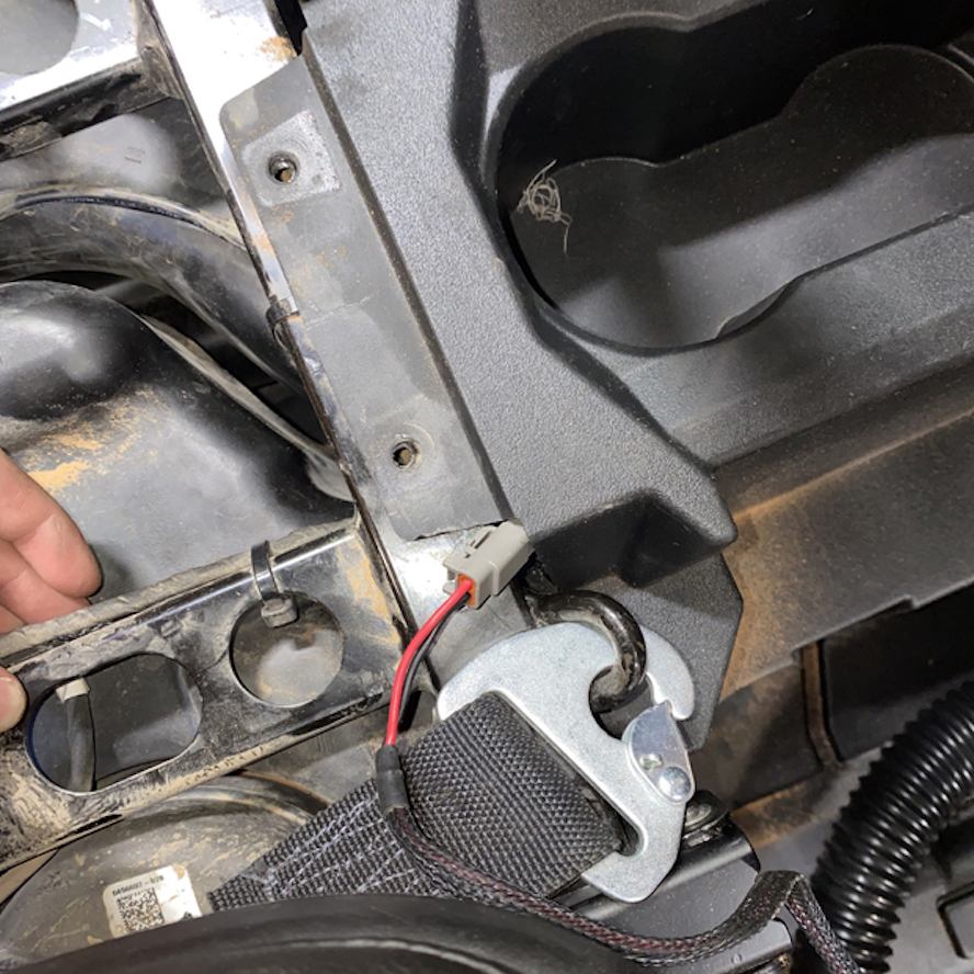
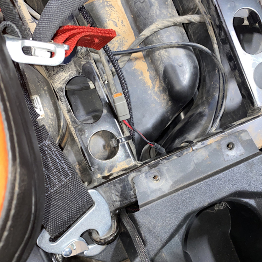
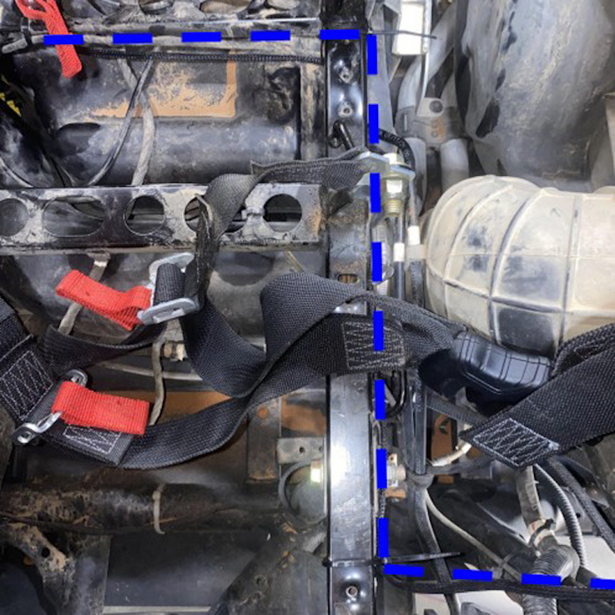
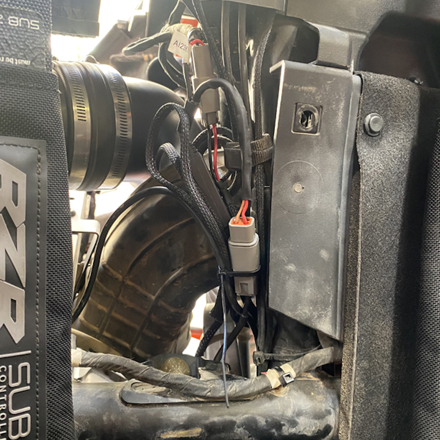
Use the shown area to pass the connector through the frame, while lifting the center console. Route and zip tie the wire underneath the frame as shown, and tuck the wire under the rear center console if applicable.
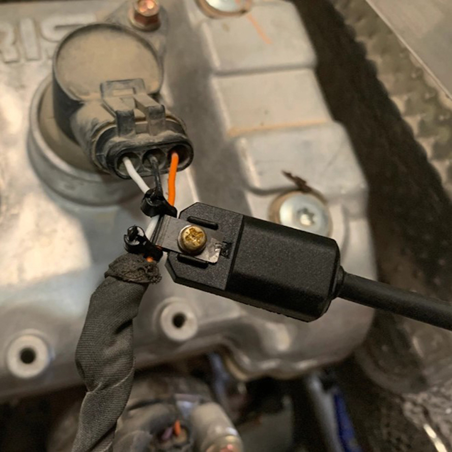
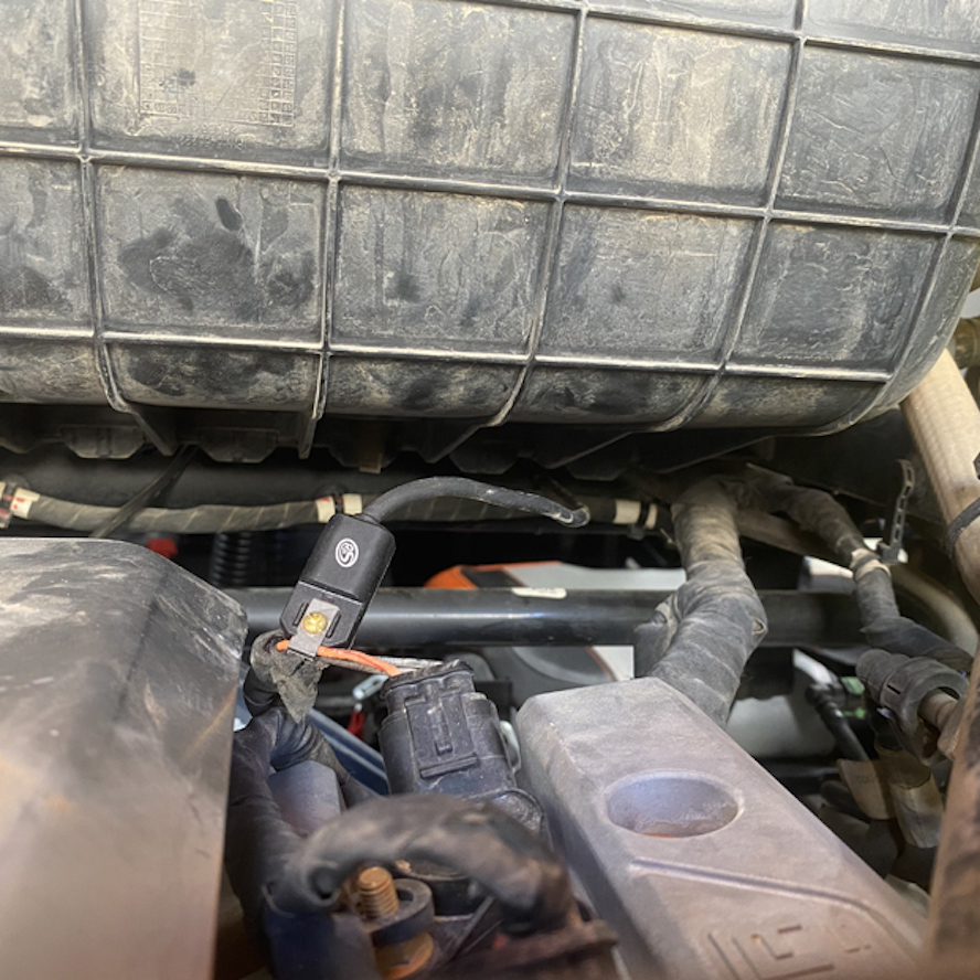
Next, locate the ignition sensor harness and remove the gold screw.
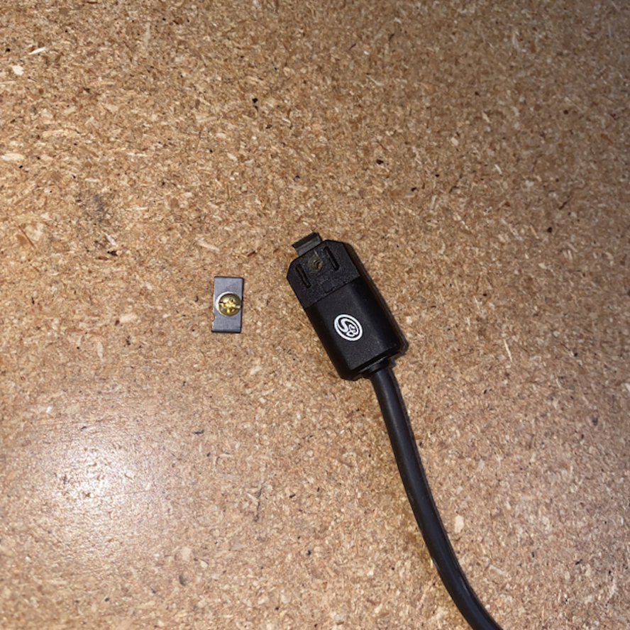
Install the ignition sensor onto the positive ignition coil wire placing it about 1” away from the connector. Make sure that the top clip piece touches the bottom clip piece on the inside. Use zip ties on each side of the connector to ensure it does not slide up or down the wire during use.
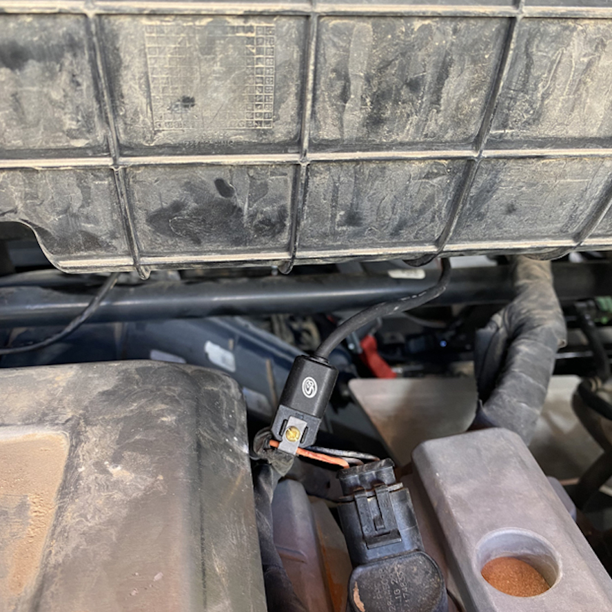
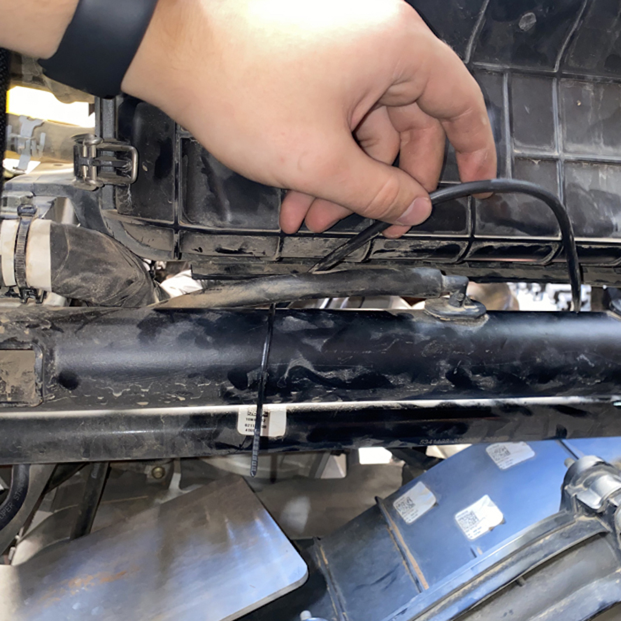
Route the connector end of the ignition sensor harness underneath the airbox and zip tie it to the bar on the other side as shown.
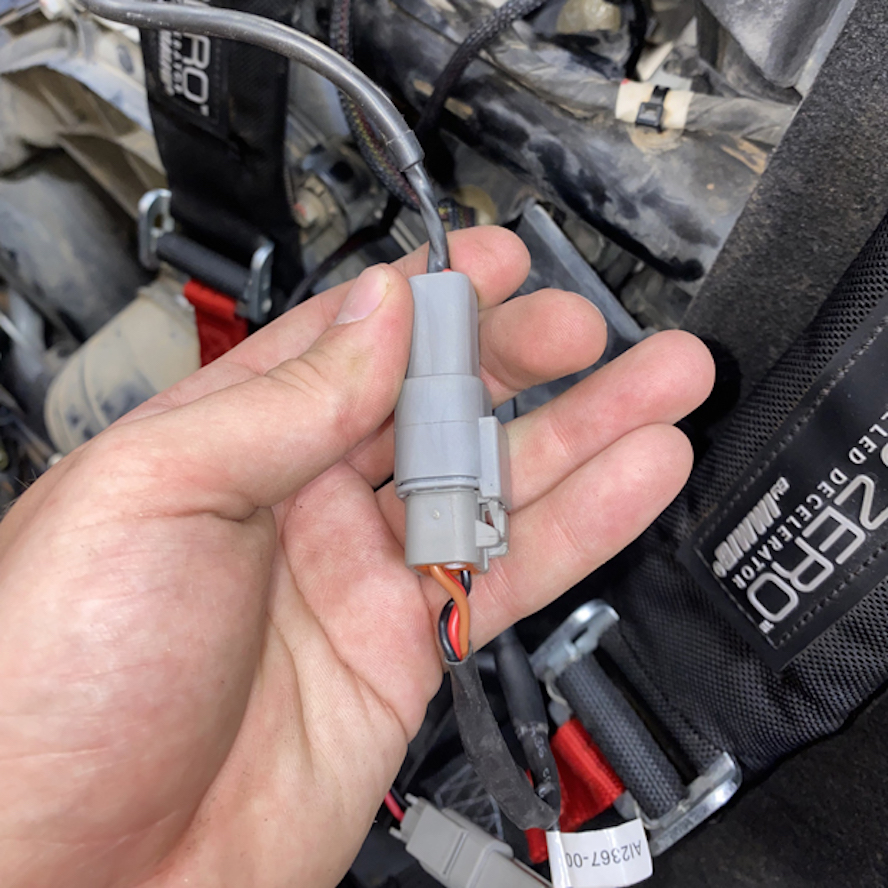
Locate the Y connector harness and familiarize yourself with it using the picture for this step. One side will have a single connector that connects to the scavenge fan from the PS. The other end has two connectors: one square 4 pin connector that connects to the ignition sensor, and one flat 3 pin connector that connects to the main power harness.
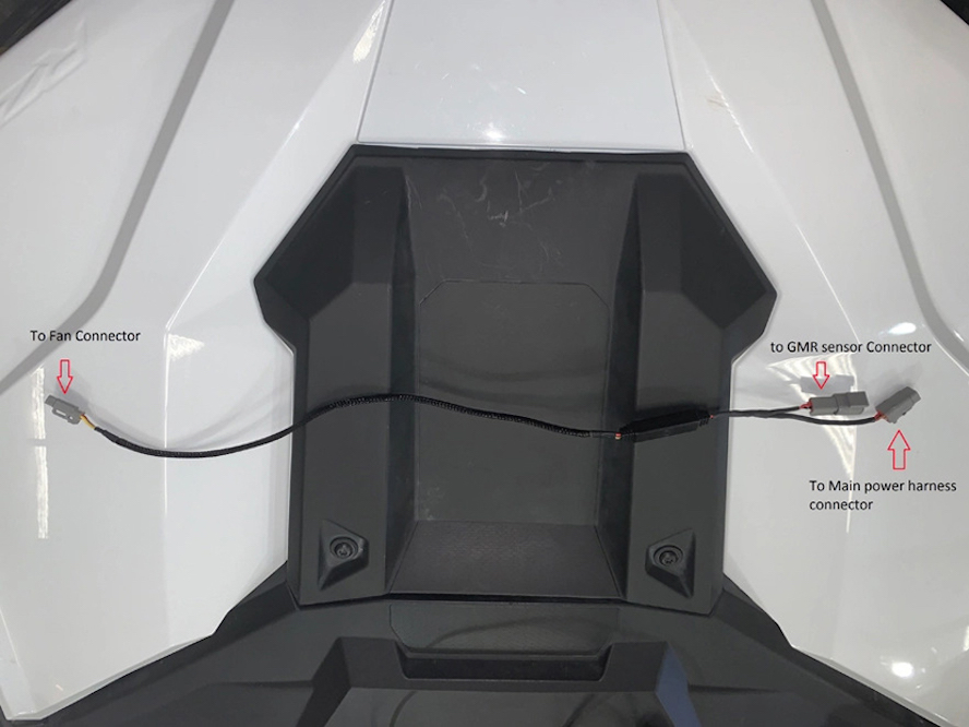
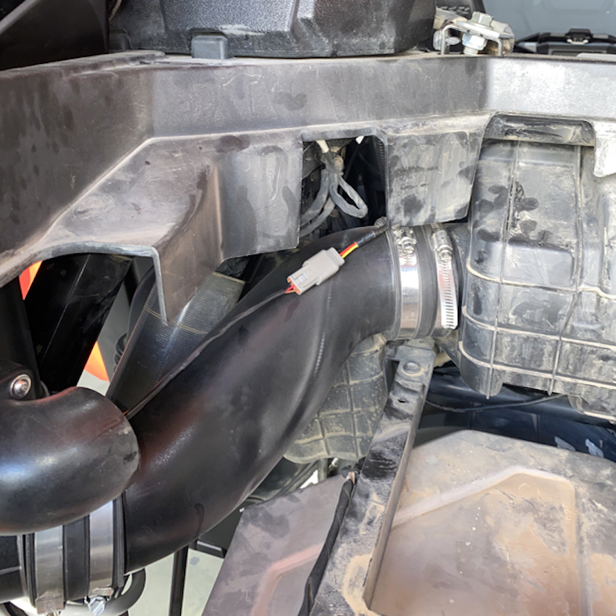
Connect the single 3 pin connector on the single connector end of the Y harness into the connector from the scavenge fan coming from the main Particle Separator unit. It should go over the tube.
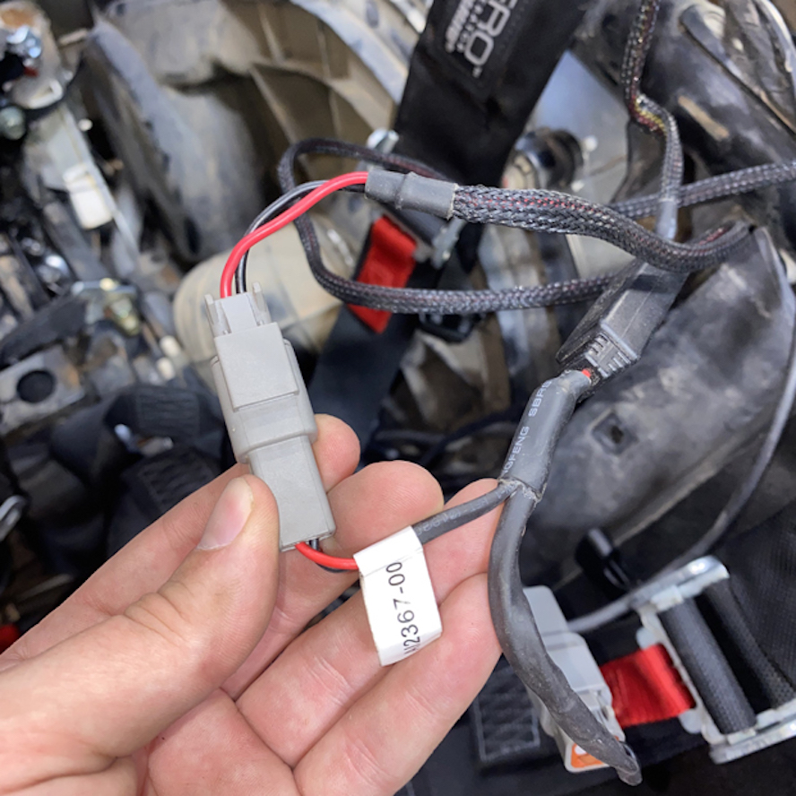
Plug the square 4 pin connector on the Y harness into the connector on the ignition sensor that you pulled through the frame earlier.
Connect the main power harness to the remaining connector on the y splitter harness.
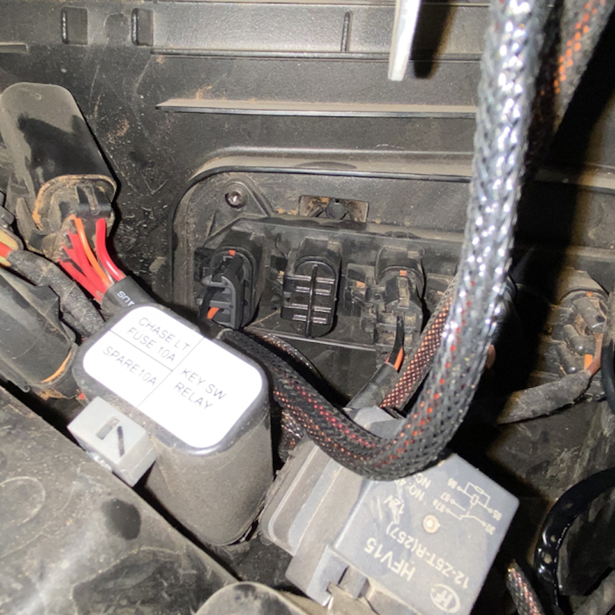
Plug the main power harness into the pulse bar in the dash.
To ensure that everything is installed correctly and there are no problems with any part of the electrical system, we need to run a test to verify the function of the whisper quiet fan technology system. If your particle behaves as these tests describe, the electrical system is functioning correctly. If the separator does not act as described, please watch our electrical system troubleshooting video to determine the cause of the misbehavior before moving on.
Ensure the wires are taught and not hanging loosely anywhere, bundling and zip tying the wires to the frame as pictured.
Reinstall the panels underneath the seats.
Reinstall the back panel.
Fasten the bottom of the center console in the front and rear if applicable.

Reinstall the rear driver side pane by putting in the area near the door first and then fastening the screws/rivets.
Reinstall the bed by putting the back prongs into place and then fastening the screws.

Reinstall the seat backs by clipping them in with the bottom prongs in their respective holes.