STEP 1
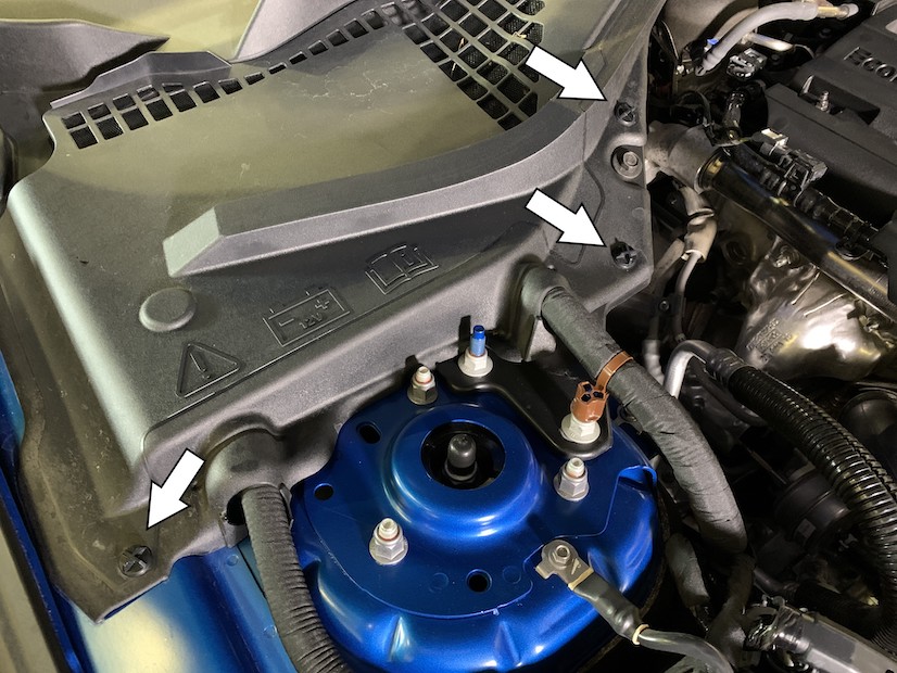
Remove the battery cover from the vehicle by removing the twist rivets found in the 3 locations shown. To remove each screw, rotate the heads counter clockwise for a few rotations and then lift up.
Note: This intake kit may not fit with the following Aftermarket Parts installed:
- Body Lift or Lowering Kit
- Custom Hood
- Throttle Body Spacer / Upgrade
Please read the entire product guide before proceeding.
- Ensure all parts are present.
- If you are missing any of the components, call our customer support at (909) 947-0015.
- Do not work on your vehicle while the engine is hot.
- Make sure the engine is turned off and the vehicle is in Park or the Parking Brake is set.
Socket Wrench
7mm, 10mm, Socket
Adjustable Wrench
Pliers
5/16” Socket/Nut Driver
Panel Popper/Flat Blade Screwdriver
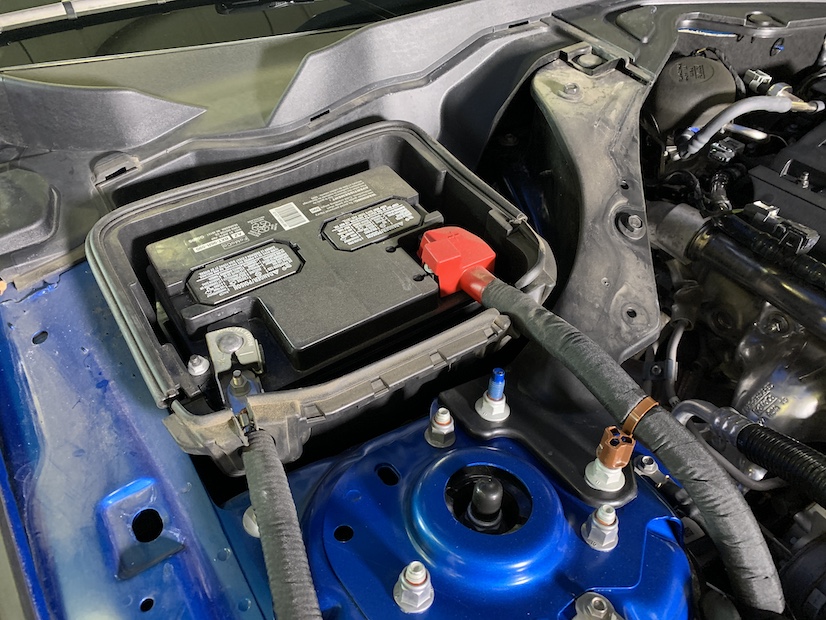
Remove the battery cover from the vehicle by removing the twist rivets found in the 3 locations shown. To remove each screw, rotate the heads counter clockwise for a few rotations and then lift up.
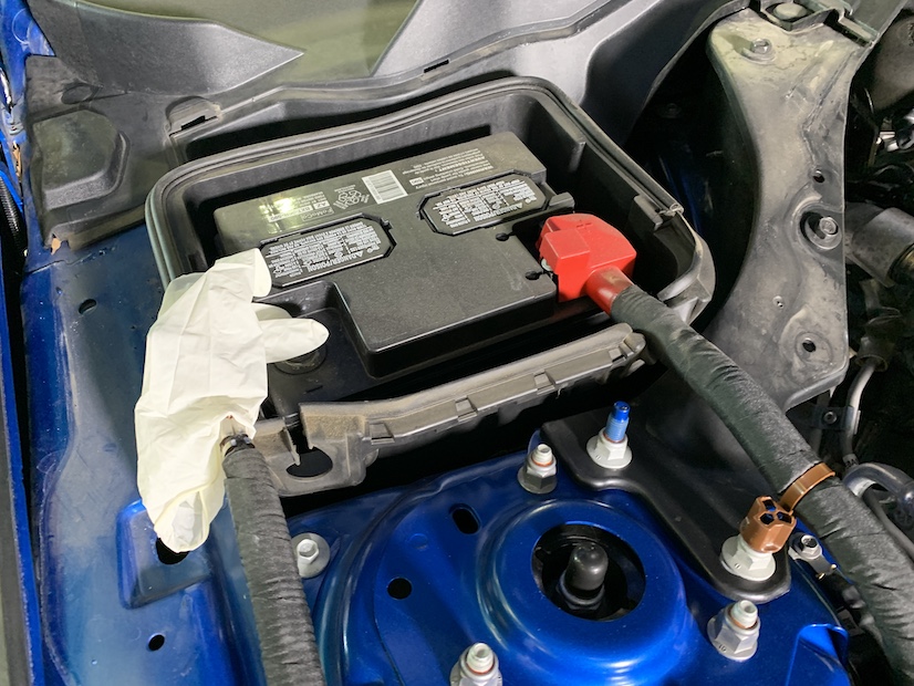
With the ignition switched off and the parking brake set, disconnect the negative battery harness on the battery. The battery must be disconnected for at least 2 hours to ensure proper functionality of the kit during use. Be sure to cover the end of the harness for the rest of the installation process so that it does not touch any part of the vehicle that acts as a ground point.
Note: Failure to disconnect the battery may cause the CEL to illuminate upon completion of the installation and subsequent operation. Do not skip this step!
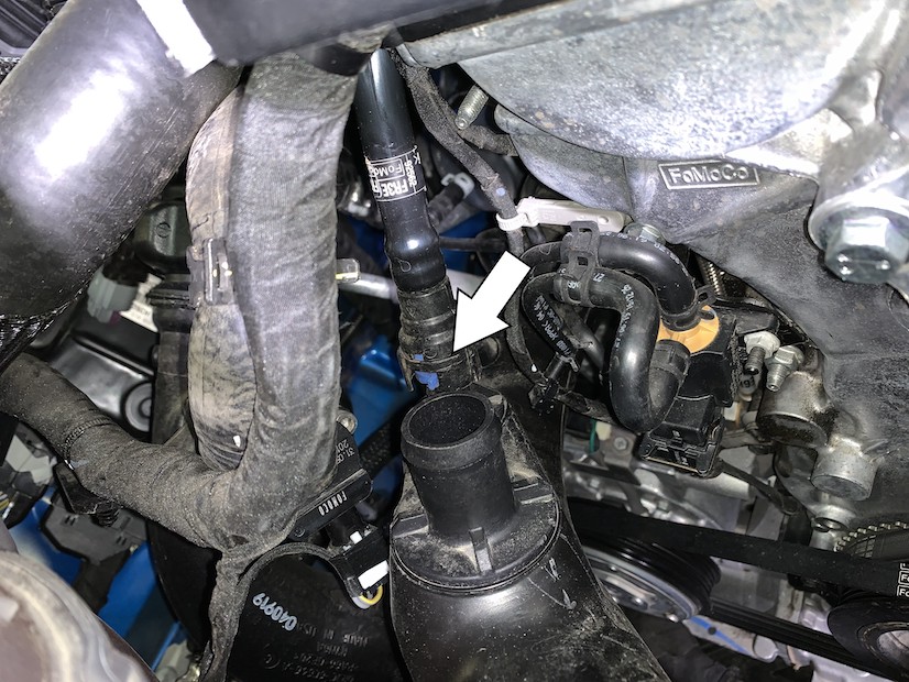
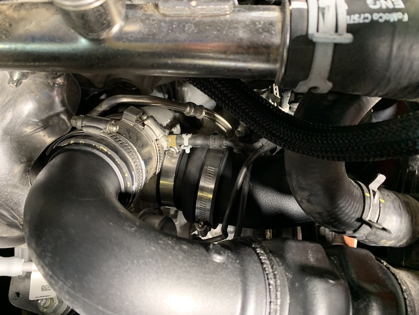
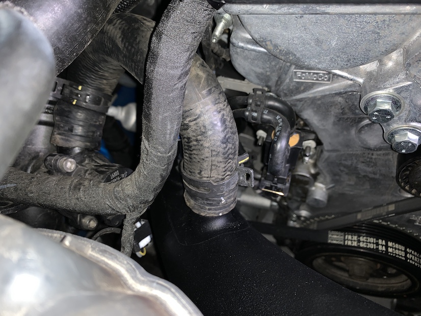
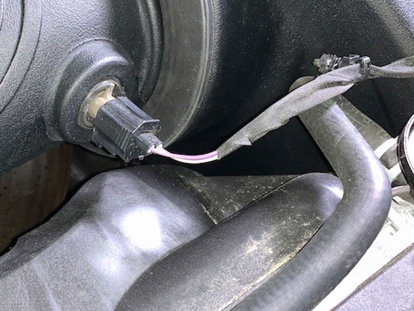
Disconnect the turbo bypass hose from the stock intake tube by squeezing the clamp with pliers and pulling up.
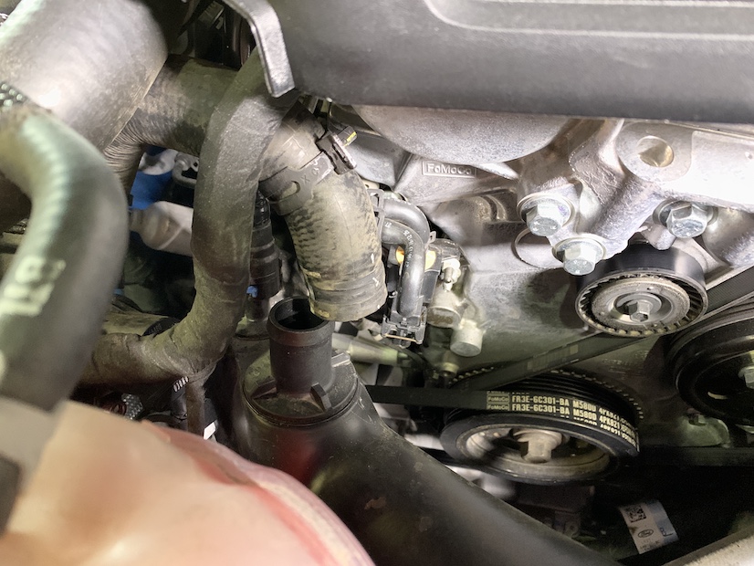
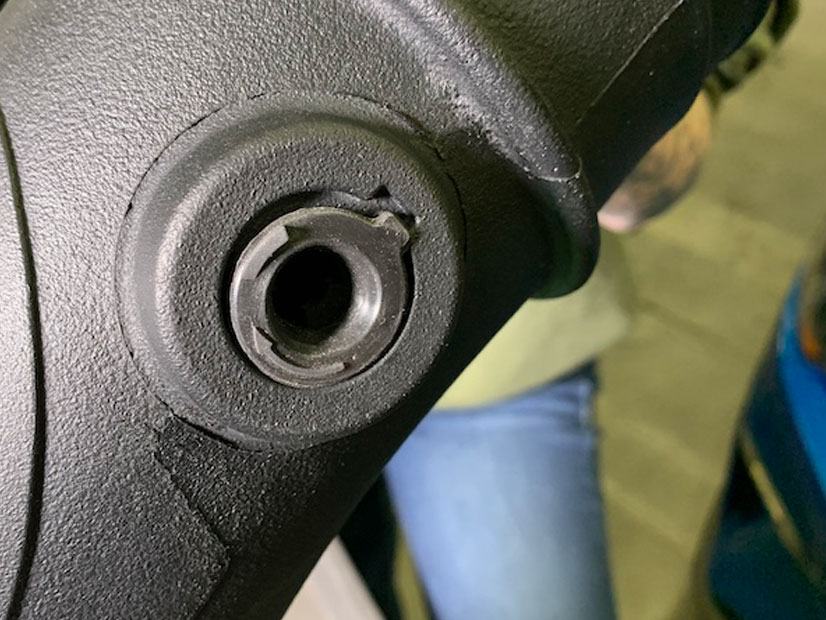
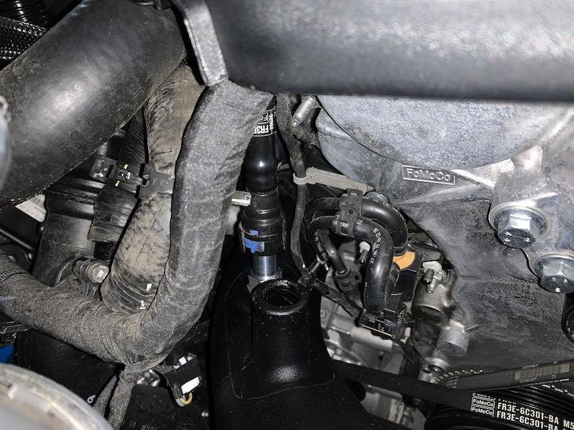
Disconnect the PCV quick connect tube from the stock intake tube by pushing the blue tab clockwise and pulling up.
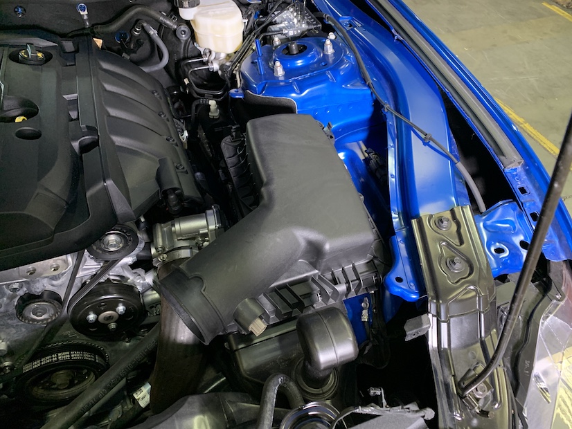
Loosen the hose clamps connecting the stock intake tube to the turbo and air box.
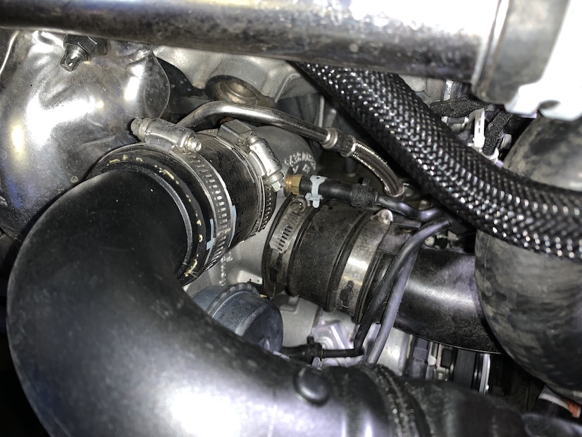
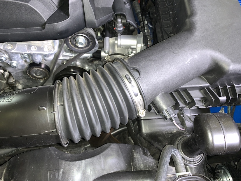
Remove the stock intake tube from the vehicle.
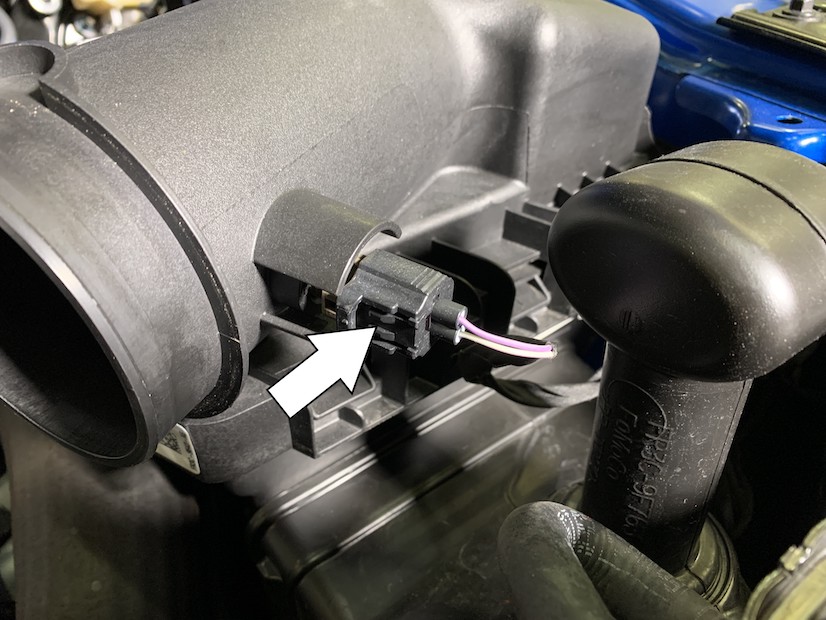
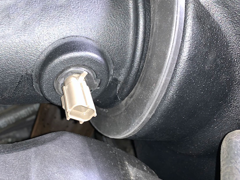
Disconnect the harness from the intake air temperature sensor by pushing down on the indicated tab and pulling out.
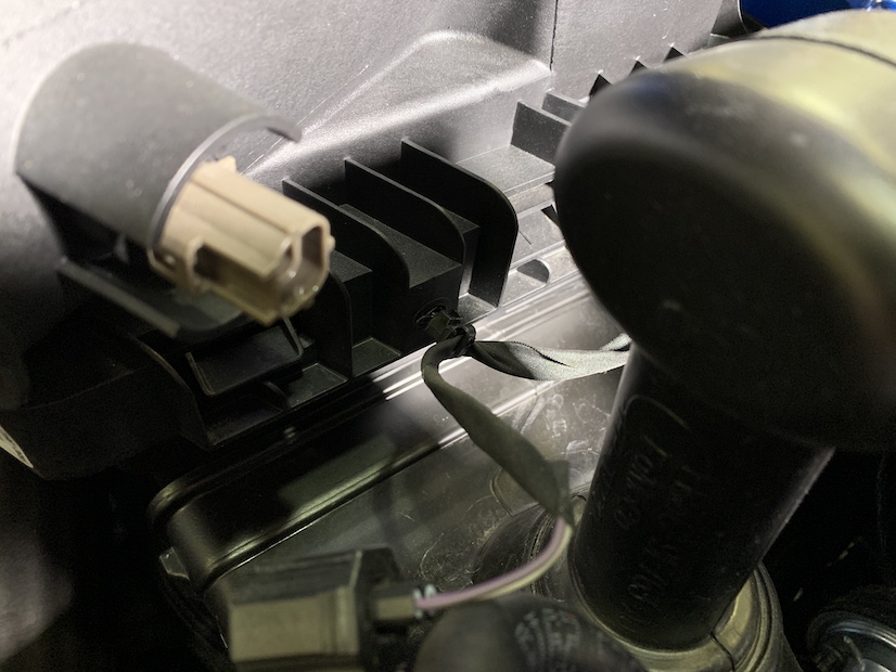
Disconnect the IAT harness from the stock air box and tab pictured.
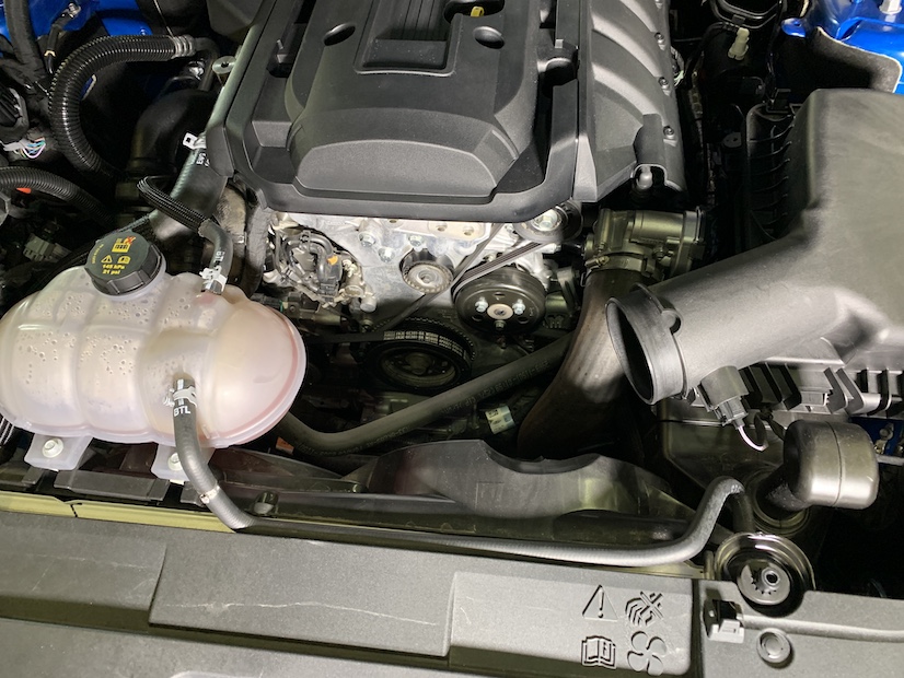
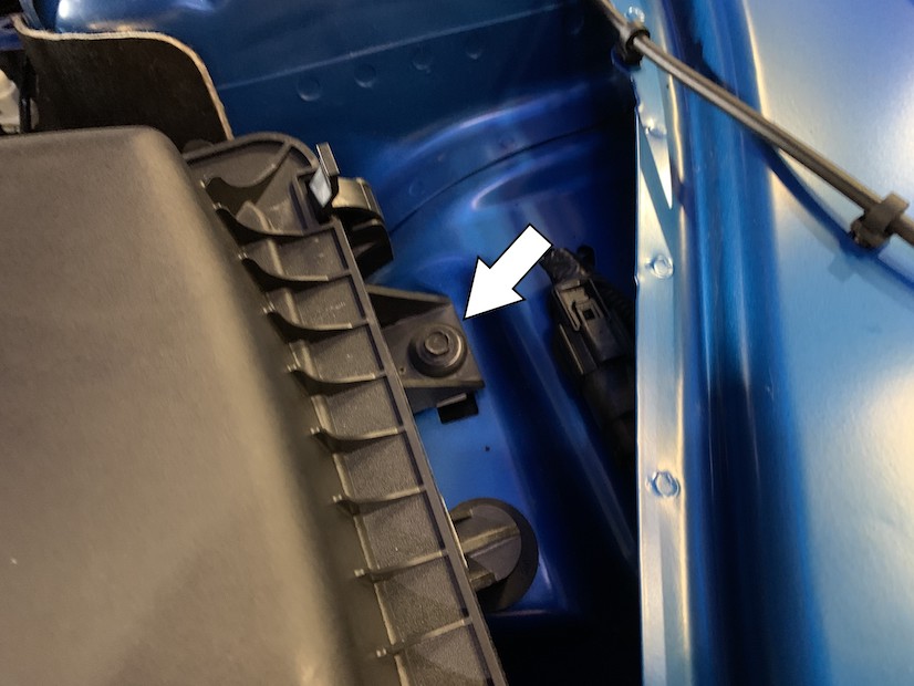
Remove the screw securing the stock intake box to the vehicle.
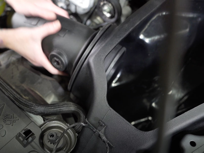
Remove the stock intake box from the vehicle by lifting it up and out.
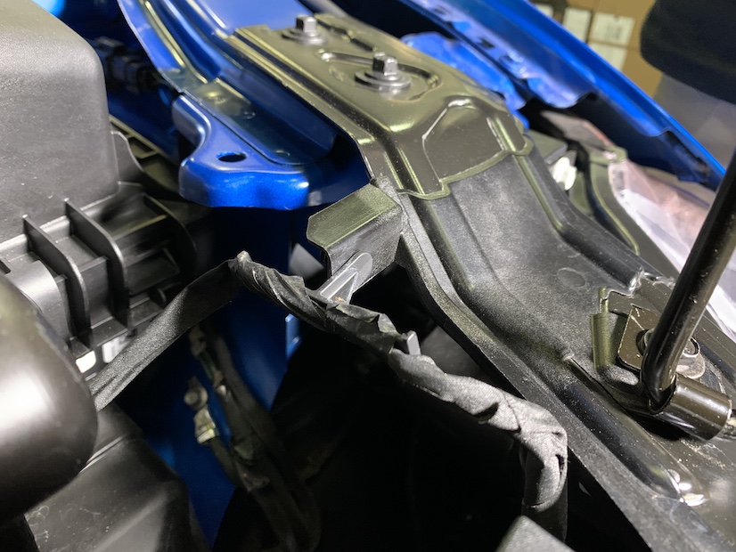
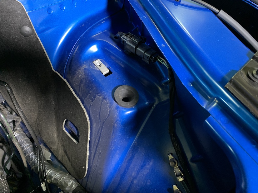
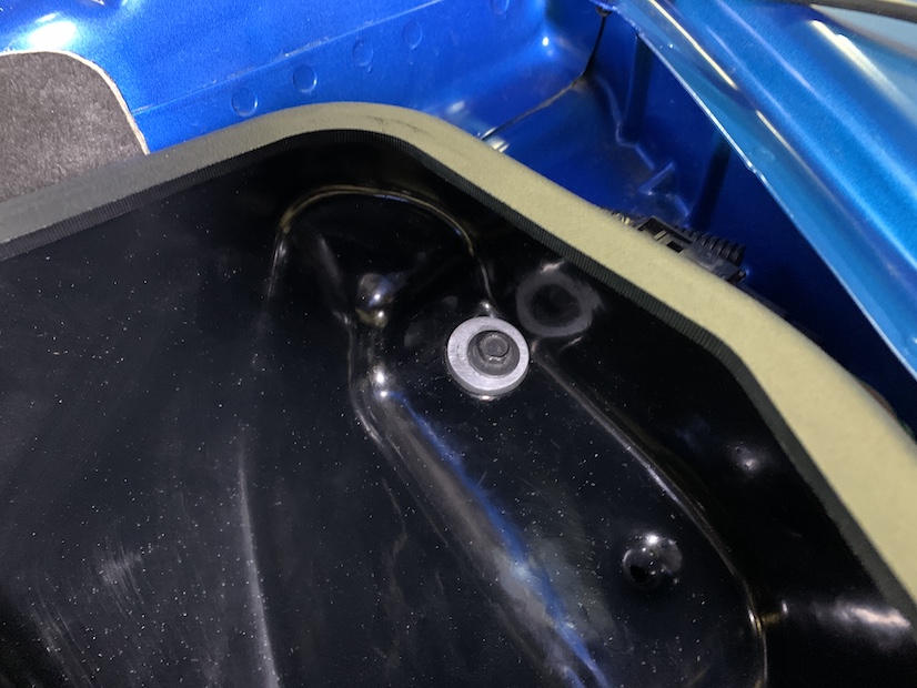
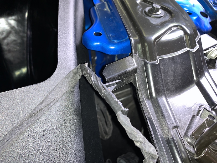
Verify that the grommet pictured did not come out of its hole on the vehicle with the stock intake box. If it did, remove it from the intake box and return it to its hole on the vehicle.
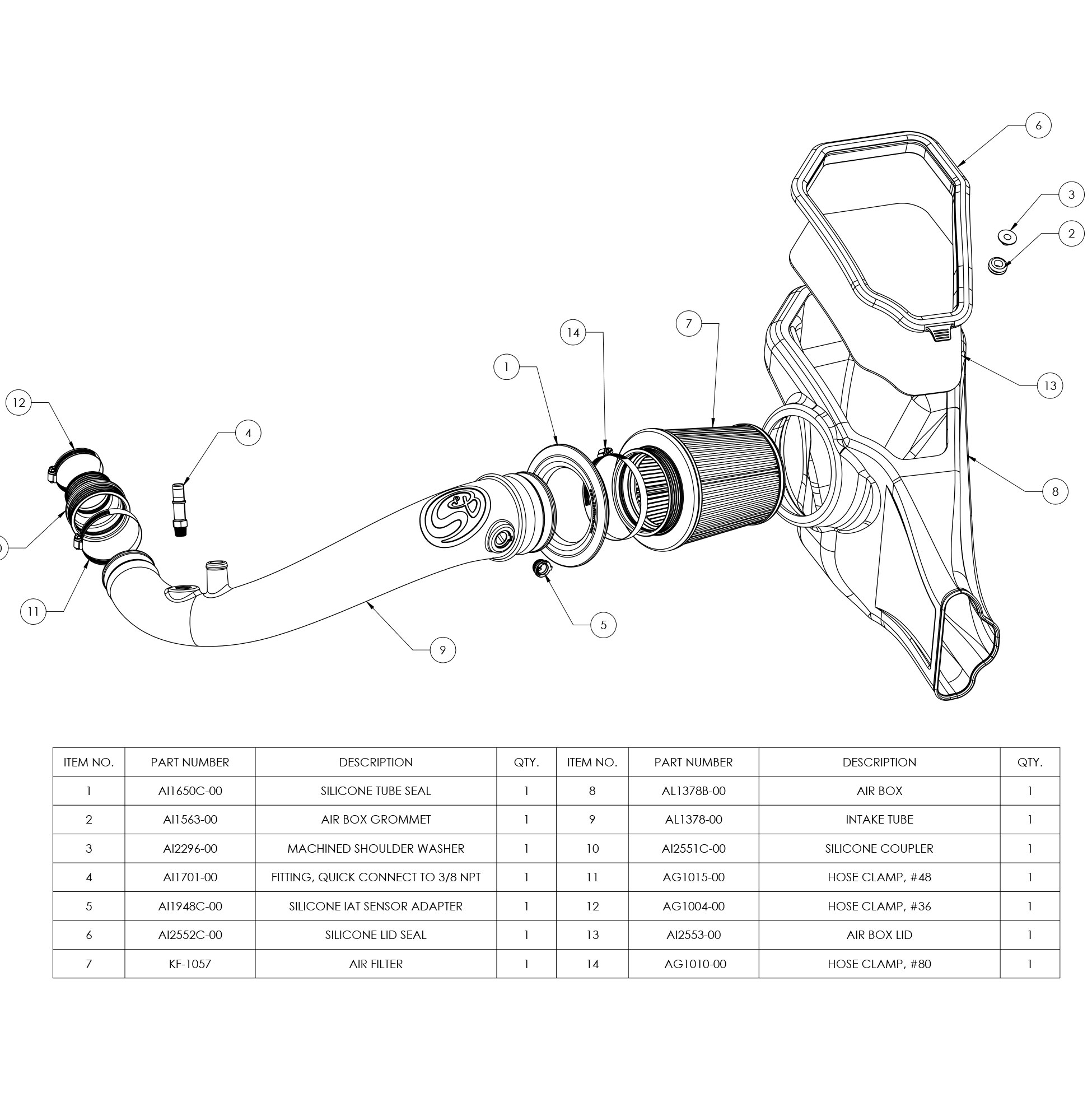
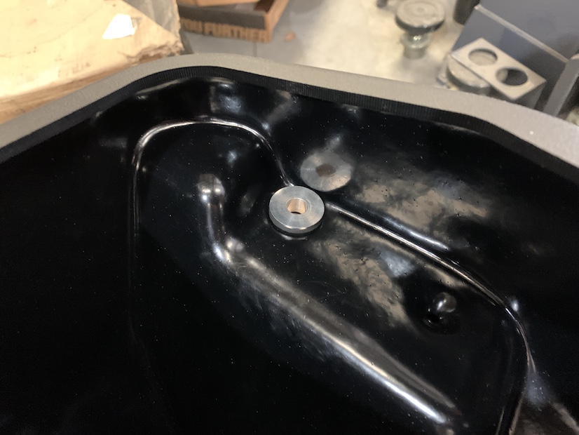
Install the rubber grommet (2) and shoulder washer (3) into the hole found on the JLT intake box (8). Then install the silicone tube seal (1) into the hole on the front of the S&B intake box.
Place the JLT intake box into the vehicle, ensuring that the front inlet completely encompasses the front grill air connection and that the prong found on the box seats snugly into the grommet shown in step 11.
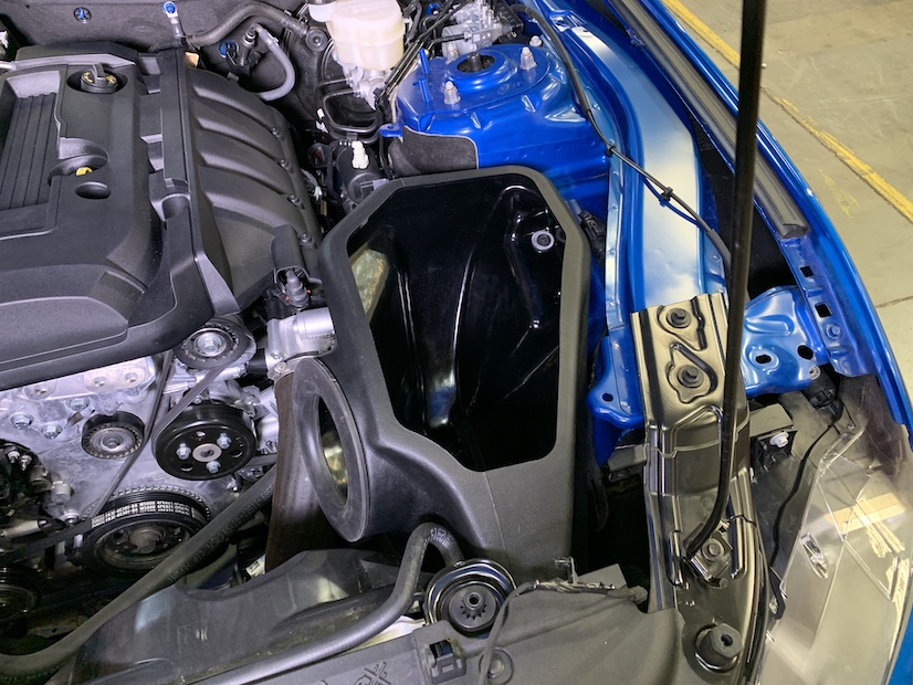
Secure the JLT intake box to the vehicle by reinstalling the screw removed in step 9.
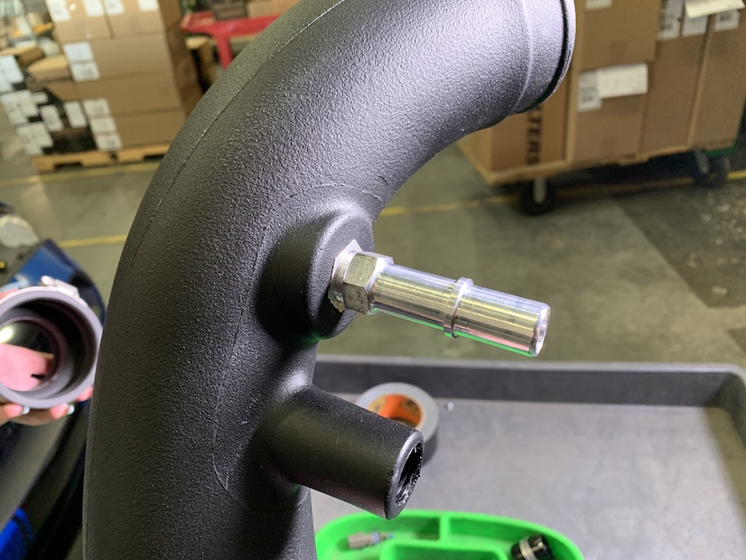
Install the IAT sensor adapter (5) onto the JLT intake tube.
Install the quick connect fitting (4) onto the JLT intake tube until hand tight, then use a crescent wrench and tighten it another one to two complete turns.
IMPORTANT: Do not over tighten, as the Quick Connect Fittings can break or the threaded inserts may strip!
Place the large side of the silicone coupler (10) around the small end of the JLT intake tube (9) and secure it with the #52 hose clamp (11). Loosely tighten the #40 hose clamp (12) around the other side of the coupler so that it doesn’t fall off.
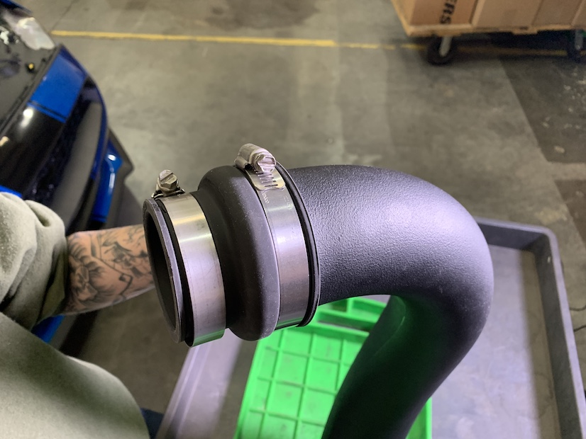
Install the JLT intake tube into the vehicle, sliding the coupler on to the end of the turbo, and pushing the large end of the intake tube through the tube seal on the S&B intake box. Then tighten the #40 hose clamp.
Connect the PCV tube to the quick connect fitting on the JLT intake tube by pressing it down until you hear a click.
Connect the turbo bypass hose to the JLT intake tube by sliding it over the inlet and securing it with the OEM clamp.
Remove the IAT sensor from the stock air box by twisting it counter clockwise and pulling out. Install that sensor onto the JLT intake tube by pressing it into the rubber adapter and twisting clockwise until the tab on the sensor passes the locking clip found on the face of the adapter.
Reconnect the IAT sensor harness to the IAT sensor.
Reconnect the IAT sensor harness to the pictured tab with the OEM push in zip tie.
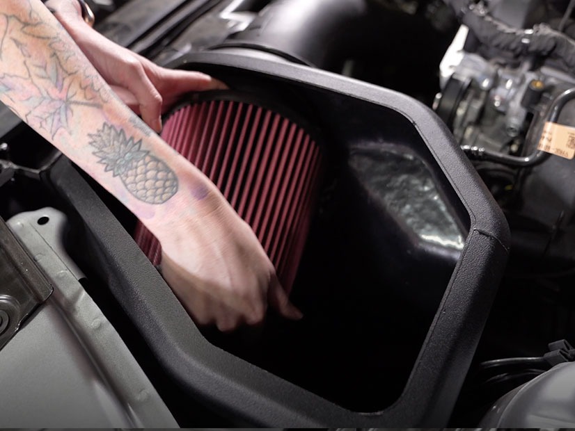
Place the filter (7) in the JLT air box and attach it to the JLT intake tube by sliding its flange around the tube opening and tightening the #80 hose clamp (14) around it.
Peel the protective paper off both sides of the clear lid (13) and slide the lid into the silicone snap in lid seal (6).
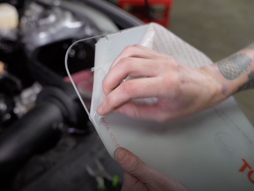
Snap the lid onto the top of the airbox by pressing down on all of the edges, ensuring that all edges of the lid are securely and completely snapped into place.
Reconnect the negative terminal on the battery.
Reinstall the battery cover and secure it down with the twist rivets removed in step 1

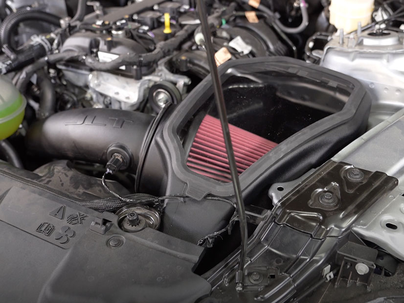
Inspect your installation, make sure the kit is properly positioned and all fasteners are secured. JLT recommends keeping all stock parts in case you would ever need to reinstall the stock intake. Affix the ID label near the intake kit.
The installation is now complete.