STEP 1
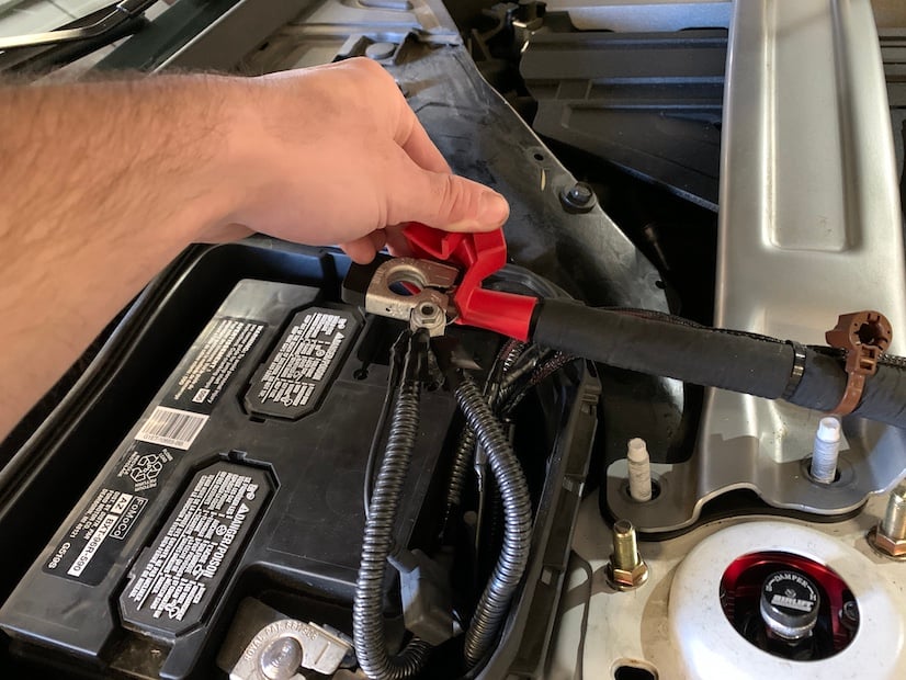
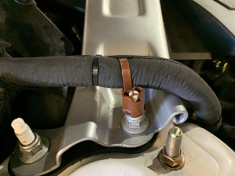
Disconnect the positive battery cable from the threaded stud by popping up the brown zip tie connector.
Note: This intake kit may not fit with the following Aftermarket Parts installed:
- Body Lift or Lowering Kit
- Custom Hood
- Throttle Body Spacer / Upgrade
Please read the entire product guide before proceeding.
- Ensure all parts are present.
- If you are missing any of the components, call our customer support at (909) 947-0015.
- Do not work on your vehicle while the engine is hot.
- Make sure the engine is turned off and the vehicle is in Park or the Parking Brake is set.
Disconnect the positive battery cable from the threaded stud by popping up the brown zip tie connector.
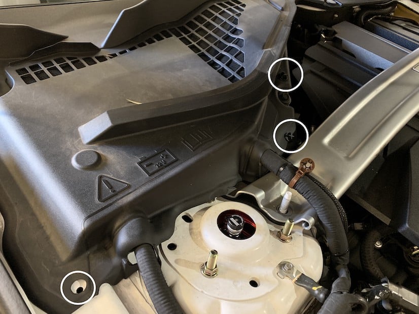
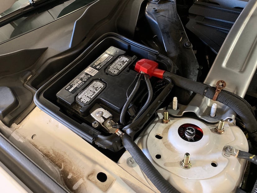
Remove the battery cover from the vehicle by removing the twist on panel screws in the 3 locations shown. To remove each screw, rotate the heads counter clockwise for a few rotations and then lift up.
With the ignition switched off and the parking brake set, disconnect the Positive battery harness on the battery. The battery must be disconnected for at least 2 hours to ensure proper functionality of the kit during use. Be sure to cover the end of the harness for the rest of the installation process so that it does not touch any part of the vehicle that acts as a ground point.
Note: Failure to disconnect the battery may cause the CEL to illuminate upon completion of the installation and subsequent operation. Do not skip this step!
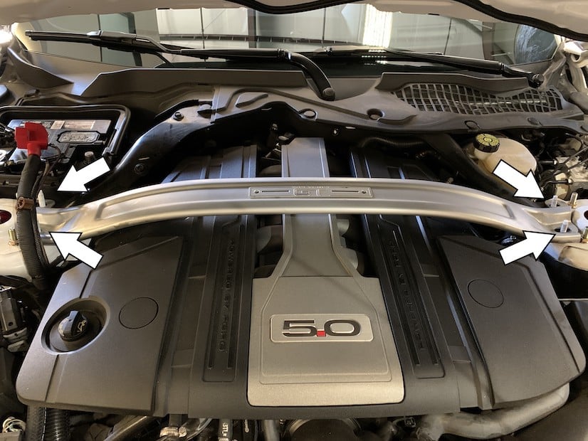
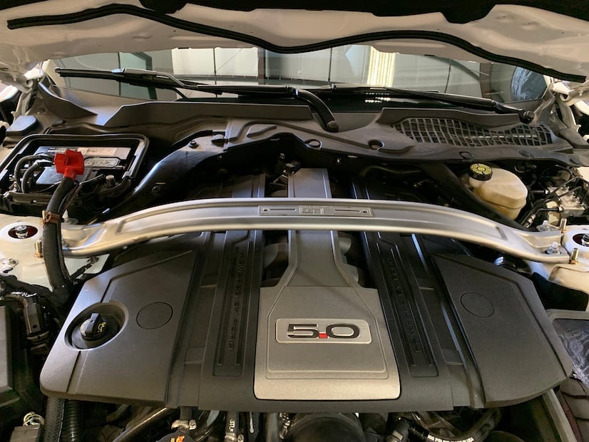
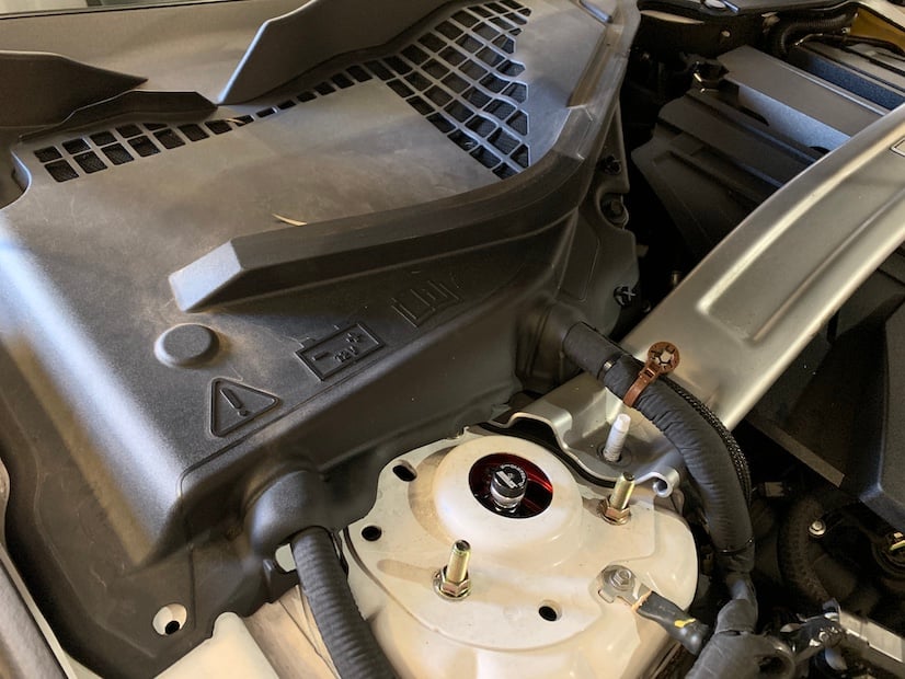
Remove the 4 nuts securing the strut tower brace to the engine bay. Then remove the strut tower brace by lifting up, avoiding the positive battery harness.
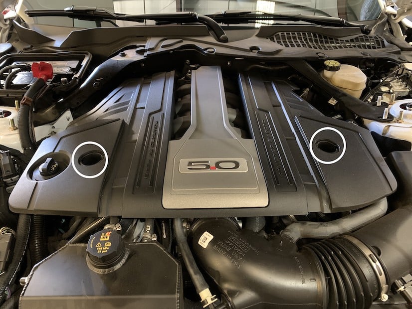
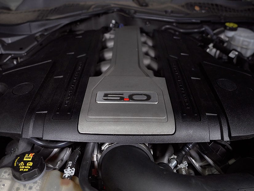
Remove the two covers shown and unscrew the nuts found below them to prepare for the removal of the engine cover. Lift up on the engine cover, popping it off of the top of the engine to gain access to the entire intake system.
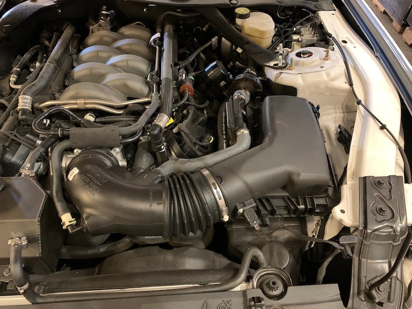
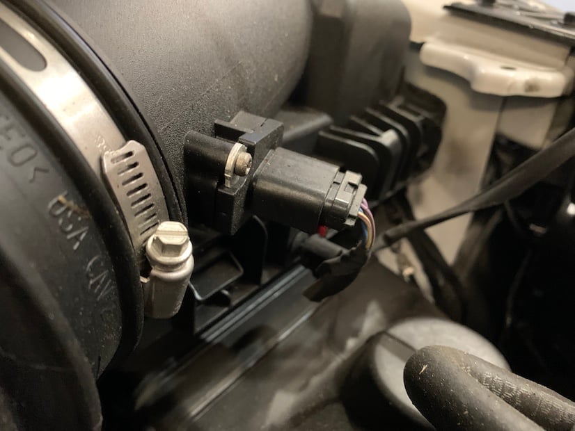
Pull out and push down on the red locking tab to disconnect the MAF sensor harness from the MAF sensor.
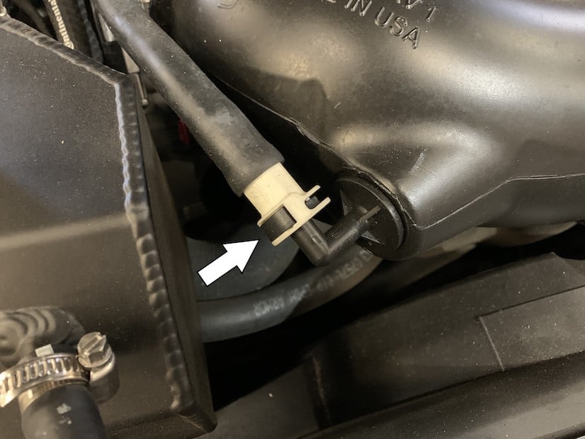
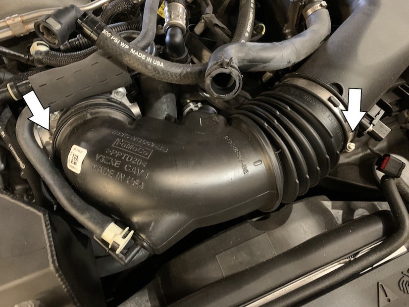
Disconnect the vacuum hose from the stock intake tube by pushing the indicated tab in and pulling out.
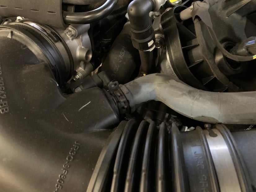
Disconnect the cabin sound tube from the stock intake tube by squeezing the clamp with pliers and pulling out.
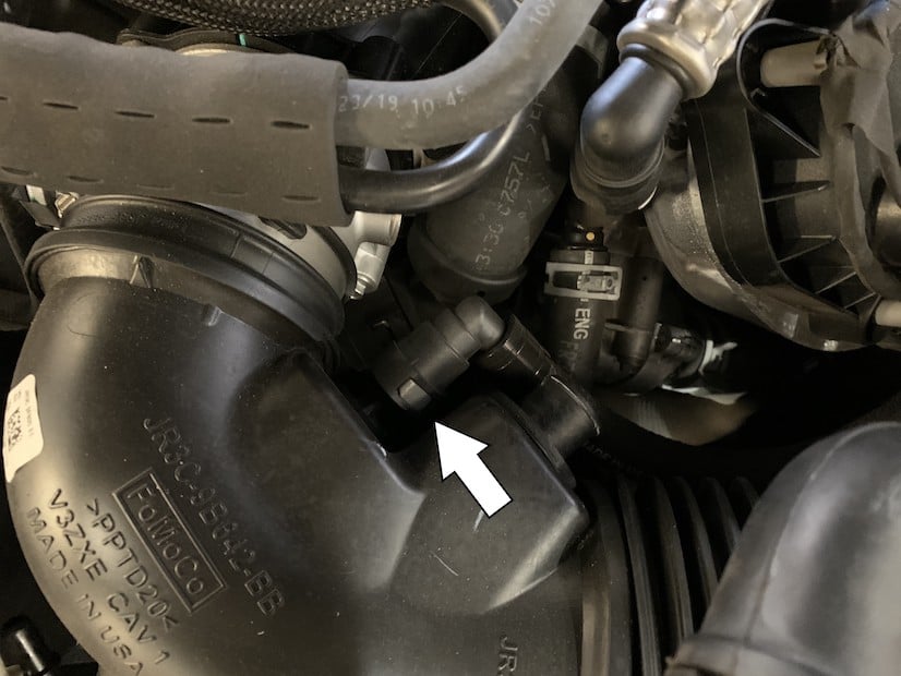
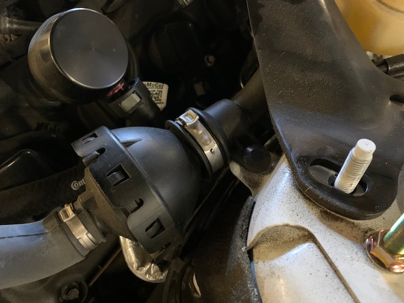
Disconnect the PCV hose from the stock intake tube by pressing in the indicated tab and pulling out.
Loosen the hose clamps found on both ends of the stock intake tube. Remove the tube from the vehicle.
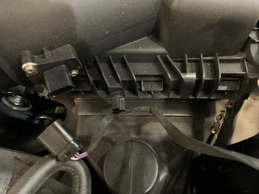
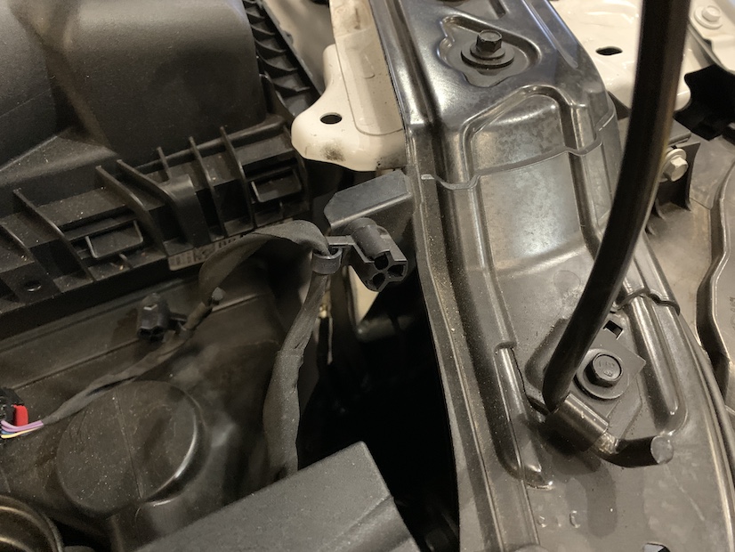
Pop off the MAF harness from it’s mounting points on the stock intake box and vehicle frame.
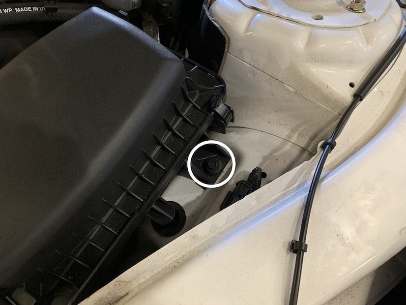
Remove the screw securing the stock intake box to the vehicle.
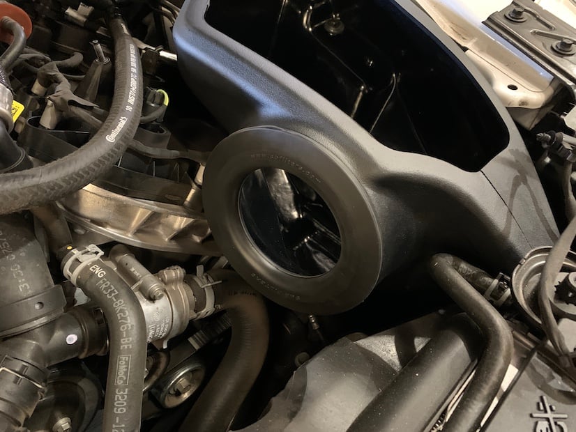
Remove the stock intake box from the vehicle by lifting it up and out.
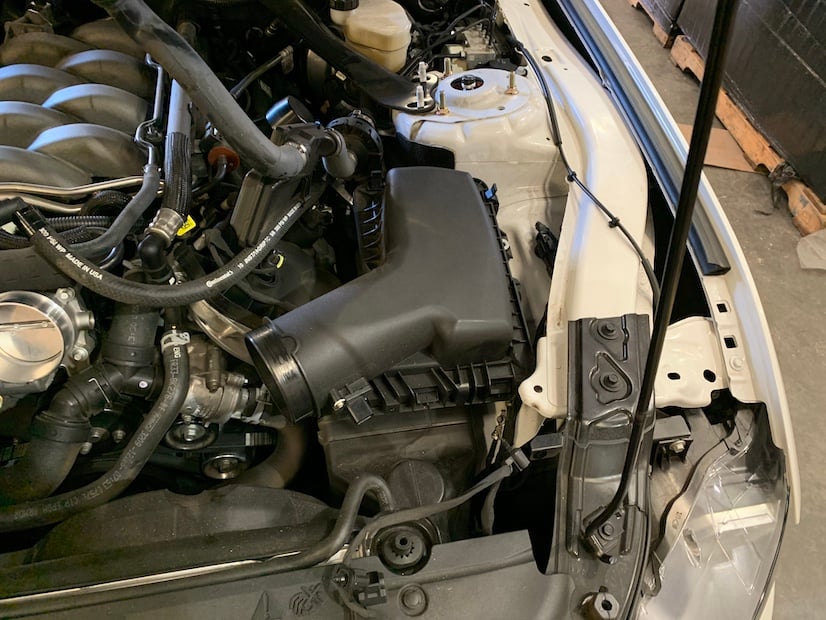
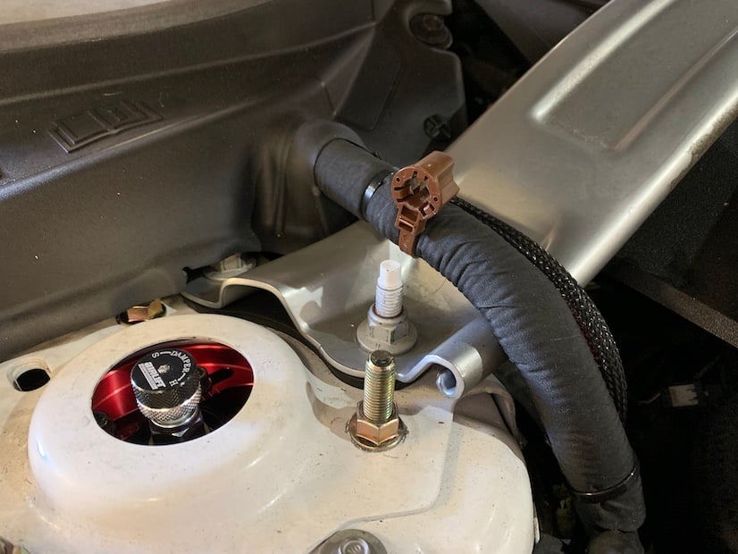
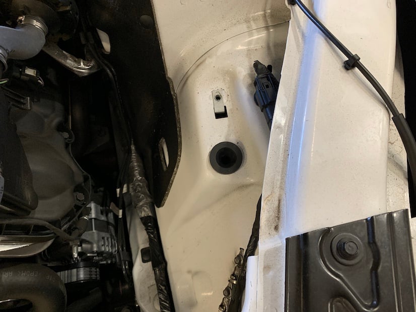
Verify that the grommet pictured did not come out of its hole on the vehicle with the stock intake box. If it did, remove it from the intake box and return it to its hole on the vehicle.
Cut off the crimp-on clamp shown on the cabin sound tube. After it has been cut off, remove from the vehicle, the section of the tube which used to connect the stock intake tube to the area where the clamp was found.
Install the S&B block off plug (18) into the rubber cup that makes up the end of the remaining cabin sound tube. Use the #24 hose clamp (19) to secure the plug within the rubber cup. The function of these last steps was to delete the cabin sound tube from the vehicle in the easiest way possible. Doing this provides for a more genuine intake sound that is not artificially boosted or pumped into the cabin. The removal of the cabin sound tube may not be skipped and is necessary in the installation of the S&B intake kit.
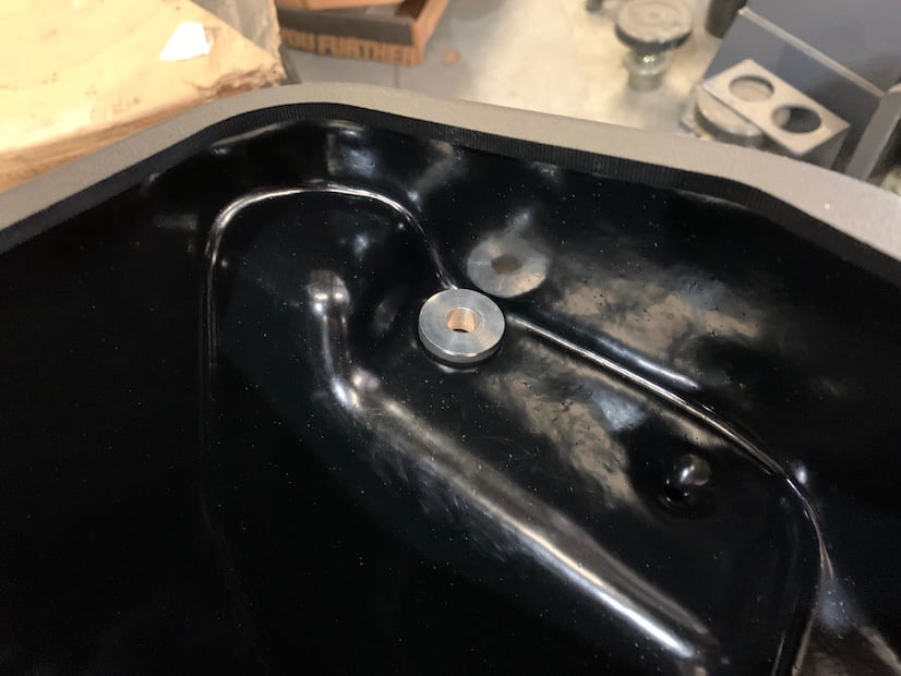
Install the rubber grommet (2) and shoulder washer (3) into the hole found on the JLT intake box (11).
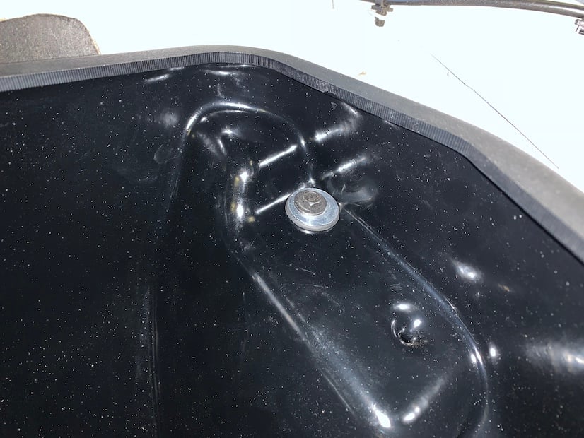
Place the JLT intake box into the vehicle, ensuring that the front inlet completely encompasses the front grill air connection and that the prong found on the box seats snugly into the grommet shown in step 14.
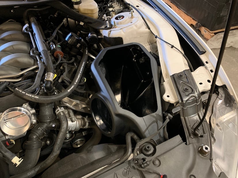
Secure the JLT intake box to the vehicle by reinstalling the screw removed in step 12.
Install the tube seal (1) on the JLT intake box.
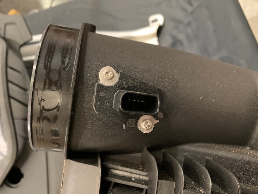
Remove the MAF sensor from the stock intake box.
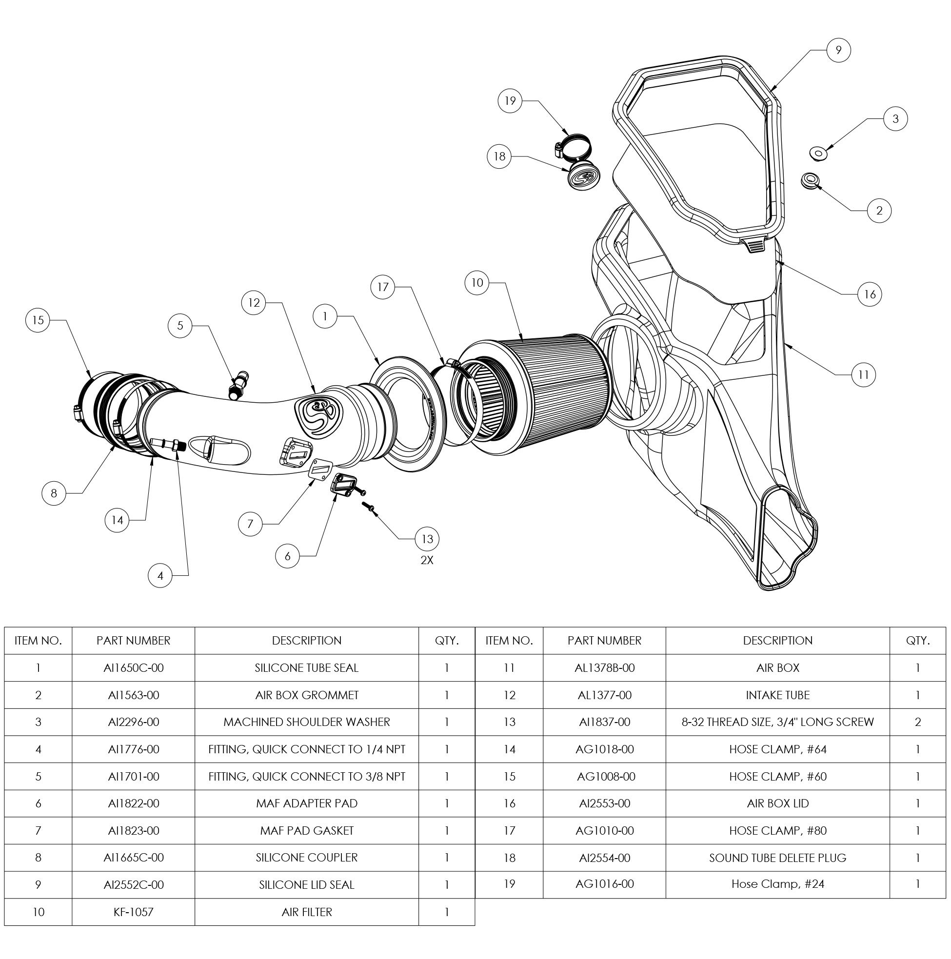
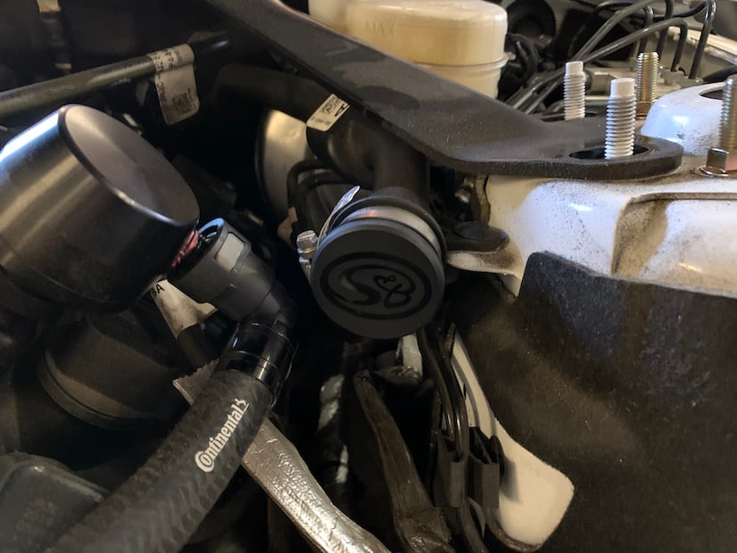
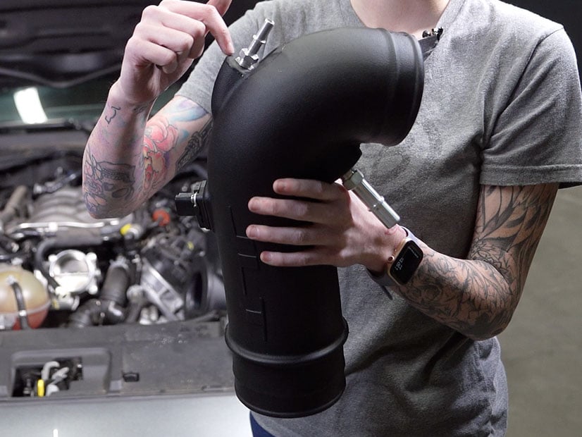
Prepare the JLT intake tube for installation by connecting all of the components shown in the picture to the intake tube. These components include the ¼ NPT quick connect (4), ⅜ NPT quick connect (5), silicone coupler (8), MAF sensor, MAF sensor pad (6) and MAF sensor gasket (7). Hand tighten quick connect fittings and then use a crescent wrench and tighten it another one to two complete turns. Secure the silicone coupler to the tube using the #64 hose clamp (14) and tighten the #60 hose clamp (15) around the other end of the coupler so that the hose clamp remains somewhat loose but doesn’t fall off.
IMPORTANT: Do not over tighten the Quick Connect Fittings as they can break or the threaded inserts may strip!
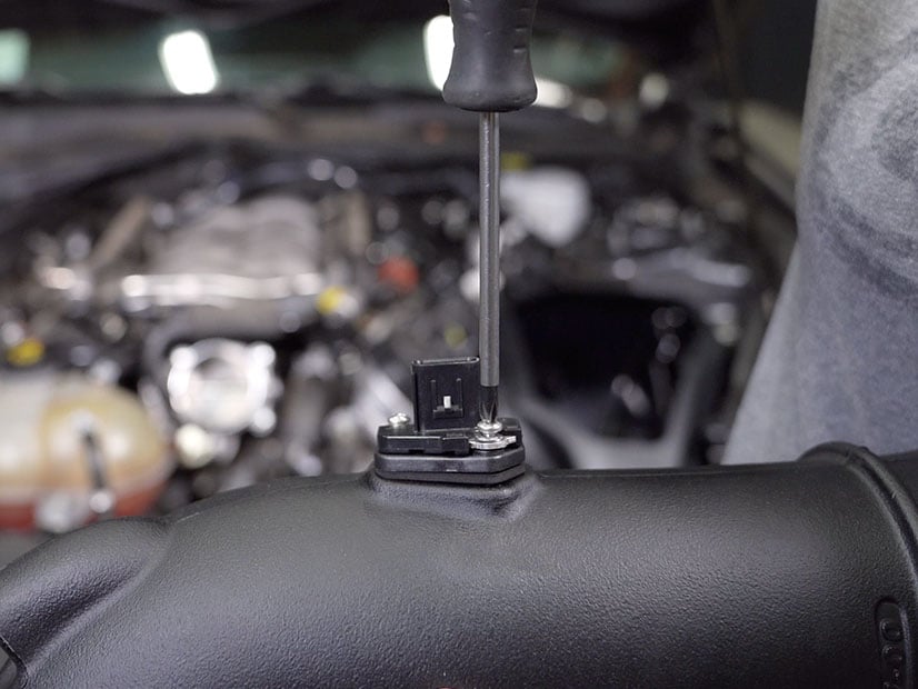
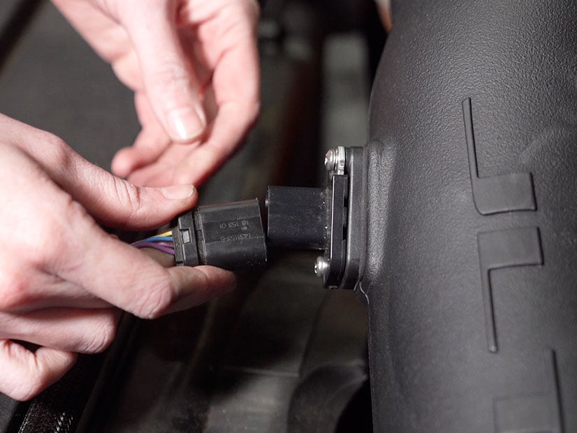
Attach the MAF sensor to the JLT intake tube using the provided MAF gasket, MAF adapter pad and philips head screws (13). The MAF gasket should be contacting the tube with the adapter, pad followed by the MAF sensor, sitting on top of it.
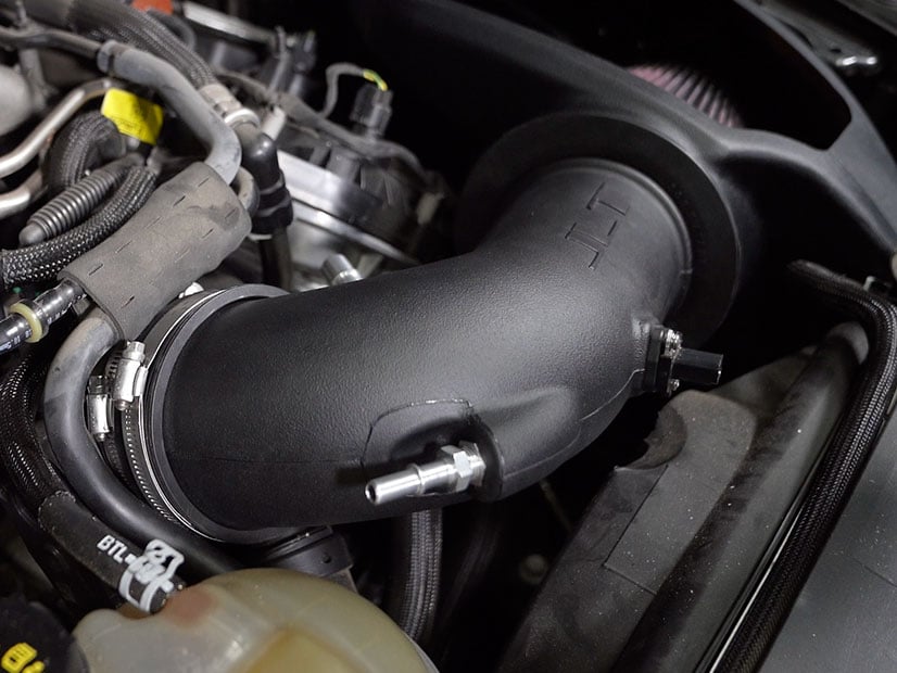
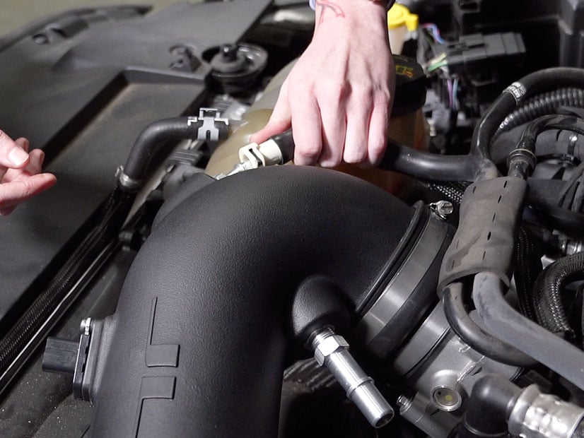
Install the JLT intake tube into the vehicle in the position shown. Tighten the #60 hose clamp, securing the JLT intake tube to the engine throttle body.
Connect the vacuum hose to the JLT intake tube, pressing it onto the ¼ NPT quick connect.
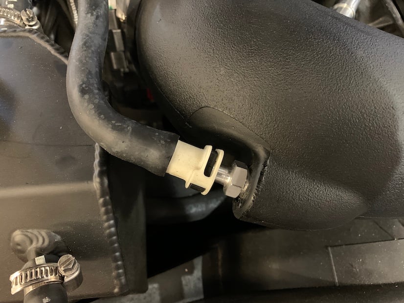
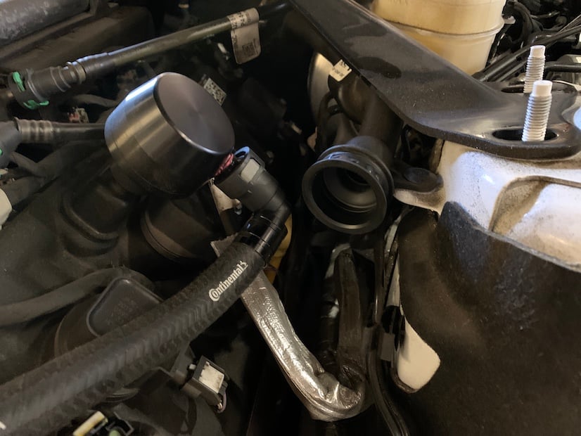
Connect the PCV hose to the JLT intake tube, pressing it onto the ⅜ NPT quick connect.
Reconnect the MAF sensor harness to the MAF sensor by pressing forward on the red locking tab.
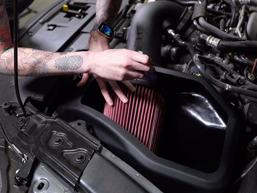
Connect the filter (10) to the JLT intake tube by placing it inside of the airbox and sliding the flange over the end of the tube. Secure the filter to the tube by tightening the #80 hose clamp (17).
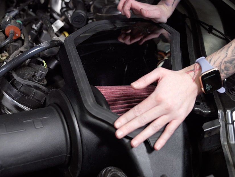
Install the lid seal (9) onto the lid (16) by stretching it around the perimeter of the lid. Snap the lid onto the top of the airbox by pressing down on all of the edges, ensuring that all edges of the lid are securely and completely snapped into place.
Reinstall the engine cover by pressing it down into the correct position on top of the engine and reinstalling the nuts removed in step 5. Replace the circular covers, concealing the installed nuts.
Reinstall the strut tower brace and the four screws removed in step 4.
Reconnect the positive terminal on the battery.
Replace the battery cover by reinstalling the twisting panel screws.
Reconnect the positive battery harness to the threaded stud by pressing down on top of the brown zip tie connector.
Inspect your installation, make sure the kit is properly positioned and all fasteners are secured. JLT recommends keeping all stock parts in case you would ever need to reinstall the stock intake. Affix the ID label near the intake kit. The installation is now complete.