STEP 1
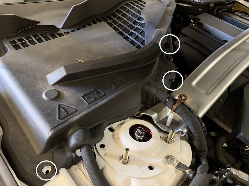
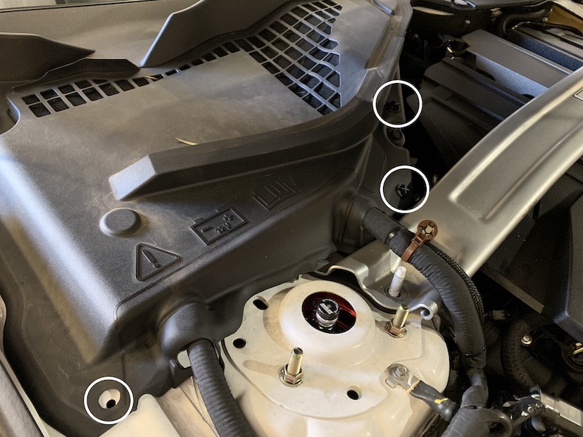
Remove the battery cover from the vehicle by removing the twist on panel screws in the 3 locations shown. To remove each screw, rotate the heads counter clockwise for a few rotations and then lift up.
Socket Wrench
7mm, 10mm Socket
10mm Deep Socket
Adjustable Wrench
5/16” Socket/Nut Driver
T20 Torx
Phillips Head Screwdriver
Panel Popper/Flat Blade Screwdriver
Remove the battery cover from the vehicle by removing the twist on panel screws in the 3 locations shown. To remove each screw, rotate the heads counter clockwise for a few rotations and then lift up.
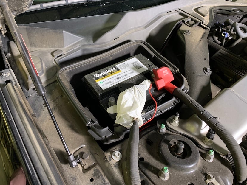
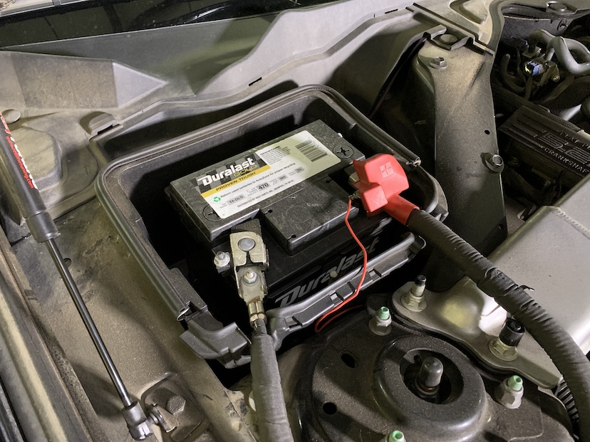
With the ignition switched off and the parking brake set, disconnect the negative battery harness on the battery. The battery must be disconnected for at least 2 hours to ensure proper functionality of the kit during use. Be sure to cover the end of the harness for the rest of the installation process.
Note: Failure to disconnect the battery may cause the CEL to illuminate upon completion of the installation and subsequent operation. Do not skip this step!
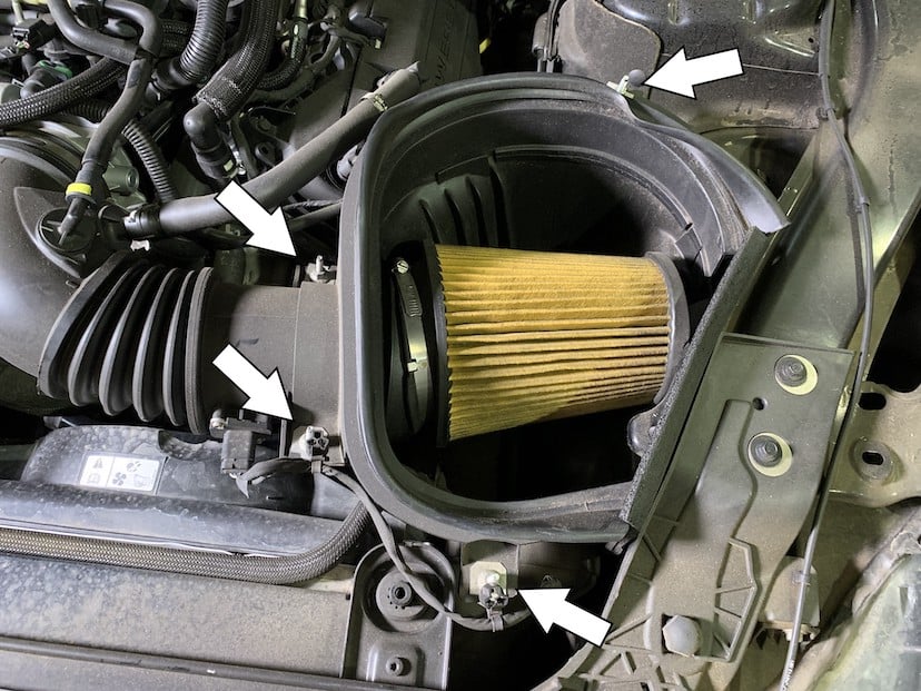
Pop off the MAF harness from it’s mounting points on the threaded studs connected to the stock intake box
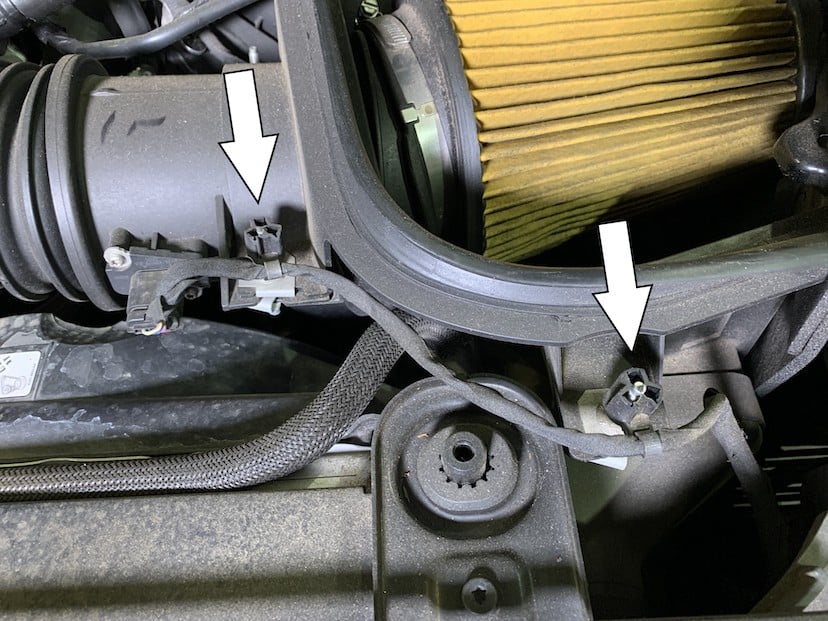
Remove the 4 threaded stud bolts from the stock intake box. Then remove the top half of the intake box from the vehicle.
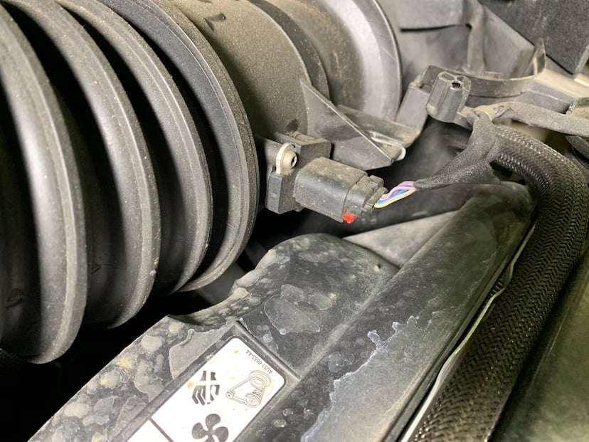
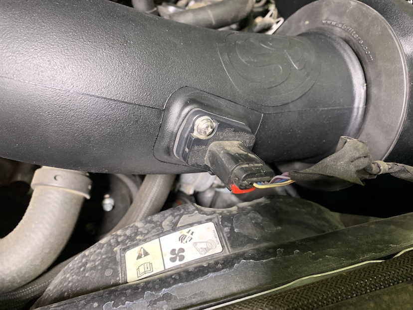
Pull out and push down on the red locking tab to disconnect the MAF sensor harness from the MAF sensor.
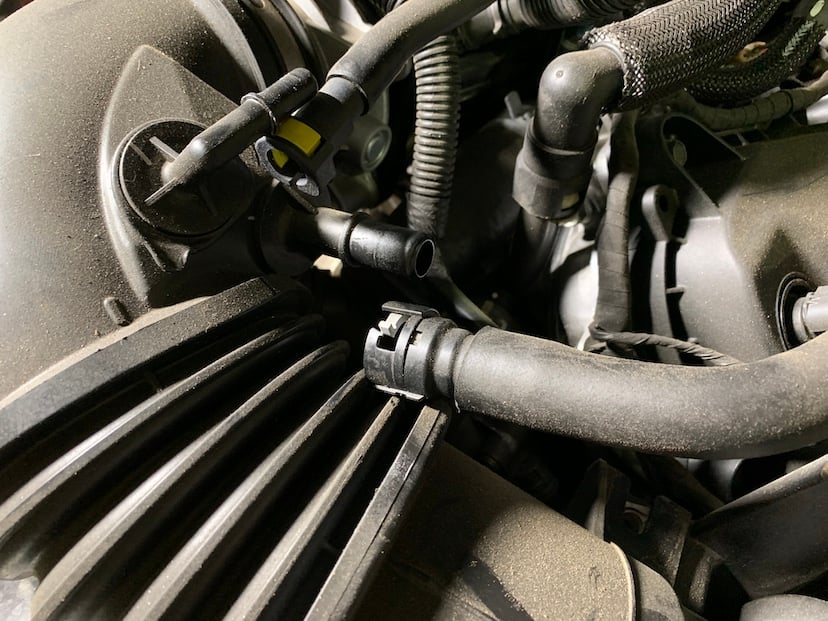
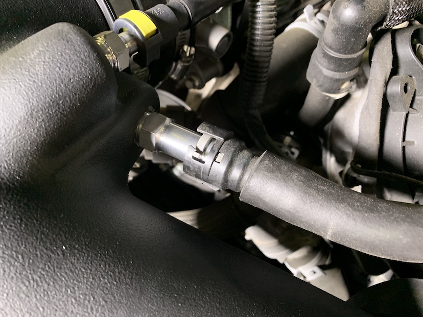
Disconnect the vacuum hose from the stock intake tube by pushing the yellow tab in and pulling out.
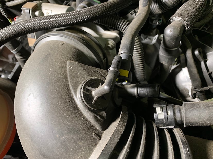
Disconnect the PCV hose from the stock intake tube by pushing the grey tab clockwise and pulling out.
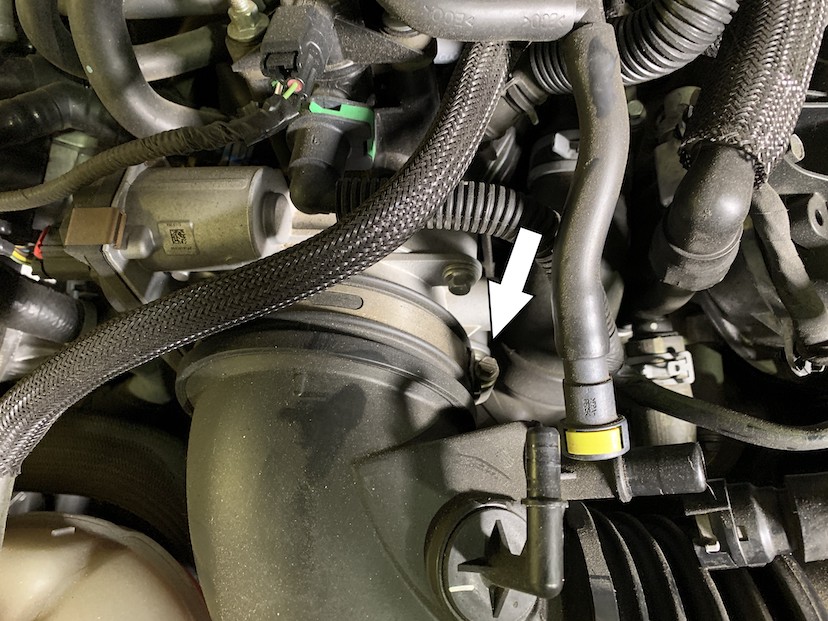
Loosen the hose clamp connecting the stock intake tube to the throttle body. Remove the stock tube and filter from the vehicle.
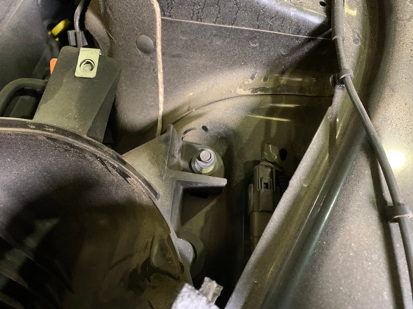
Remove the screw securing the stock intake box to the vehicle.
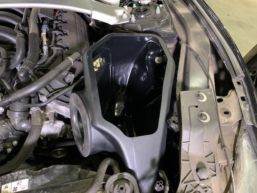
Remove the bottom half of the stock intake box and foam trim from the vehicle by lifting the intake box up and out. Be careful to not force the foam trim past the frame tab or it will rip.
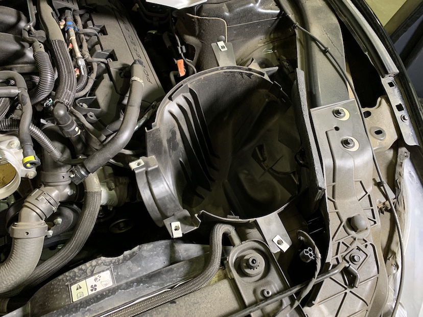
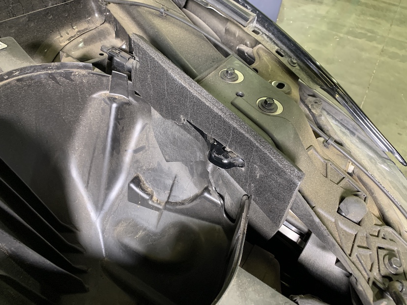
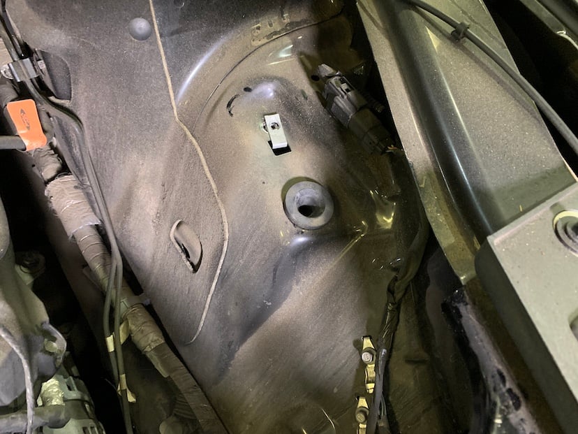
Verify that the grommet pictured did not come out of its hole on the vehicle with the stock intake box. If it did, remove it from the intake box and return it to its hole on the vehicle.
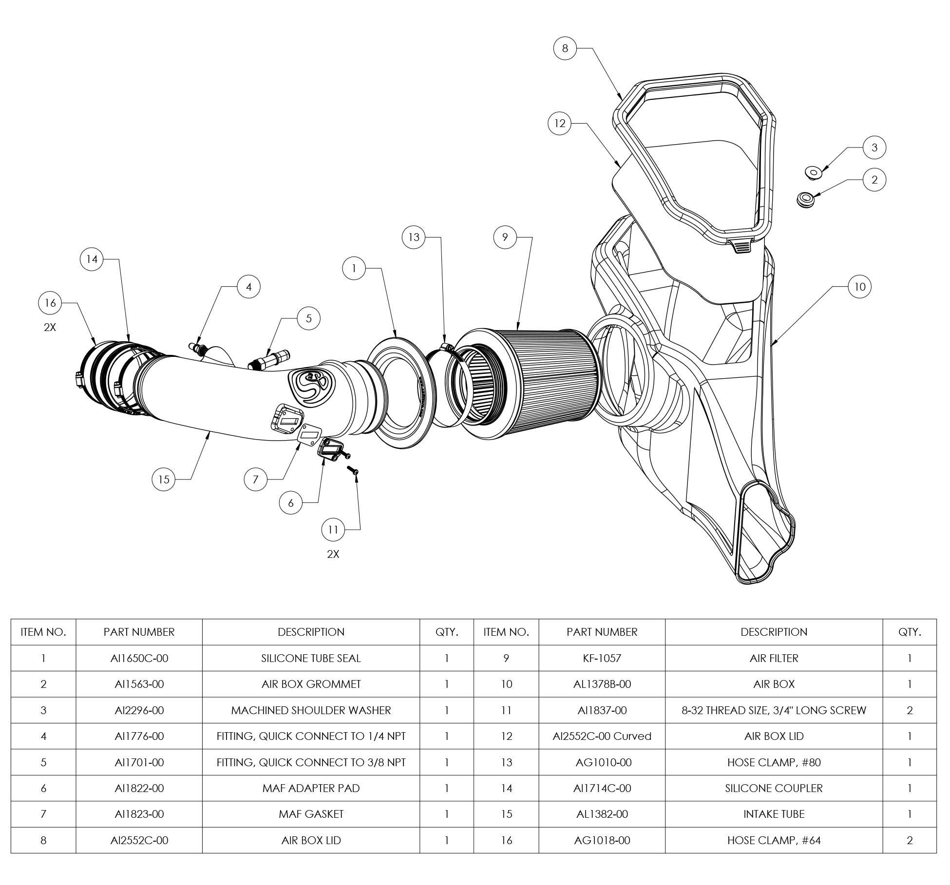
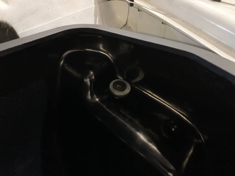
Install the rubber grommet (2) and shoulder washer (3) into the hole found on the S&B intake box.
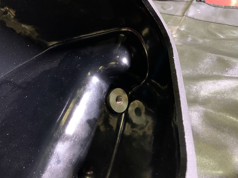
Install the tube seal (1) onto the S&B intake box.
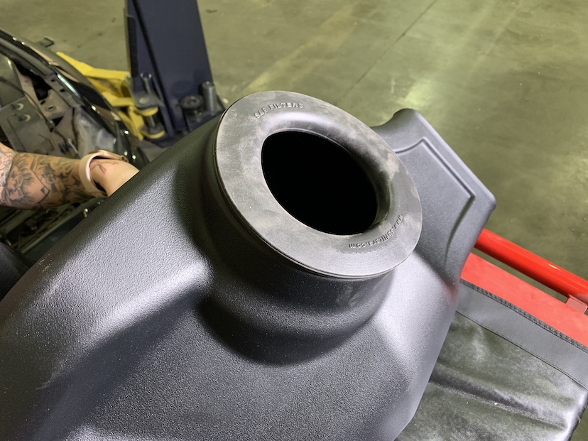
Place the S&B intake box (11) into the vehicle, ensuring that the front inlet completely encompasses the front grill air connection and that the prong found on the box seats snugly into the grommet shown in step 12.
Secure the S&B intake box to the vehicle by reinstalling the screw removed in step 10.
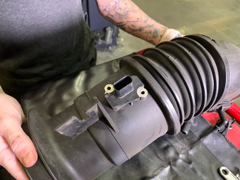
Remove the MAF sensor from the stock intake box.
Part A
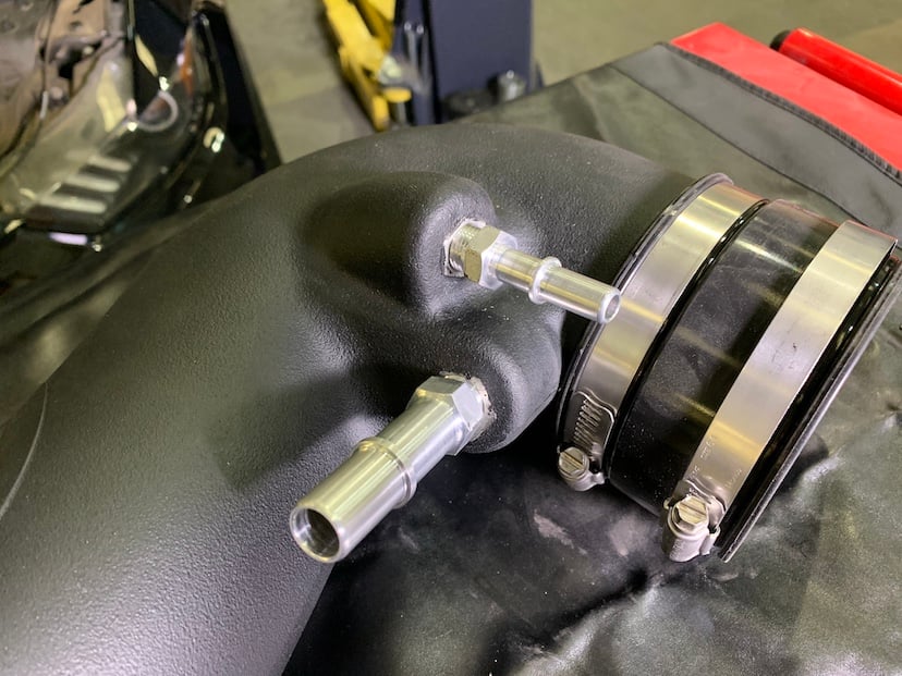
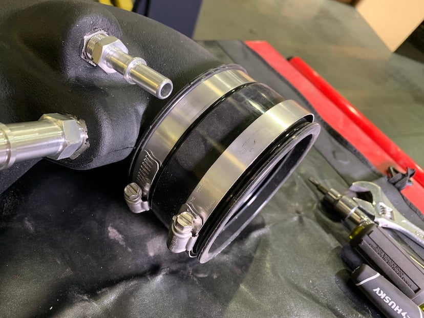
Prepare the S&B intake tube for installation by connecting all of the components shown in the picture to the intake tube. These components include the ¼ NPT quick connect (5), ⅜ NPT quick connect (4), silicone coupler, MAF sensor, MAF sensor pad (6) and MAF sensor gasket (7). Secure the silicone coupler (8) to the tube using a #64 hose clamp (14) and tighten the other #64 hose clamp around the other end of the coupler so that the hose clamp remains somewhat loose but doesn’t fall off.
Part B
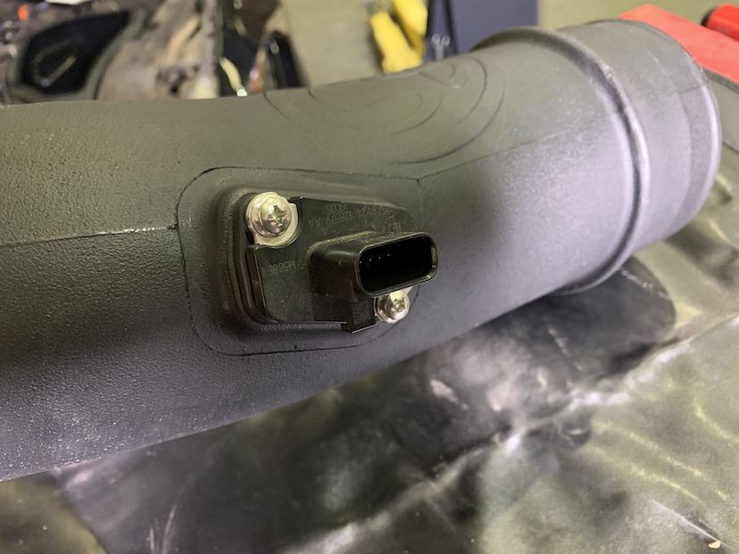
Attach the MAF sensor to the S&B intake tube using the provided MAF gasket, MAF adapter pad and phillips head screws (13). The MAF gasket should be contacting the tube with the adapter, pad followed by the MAF sensor, sitting on top of it.
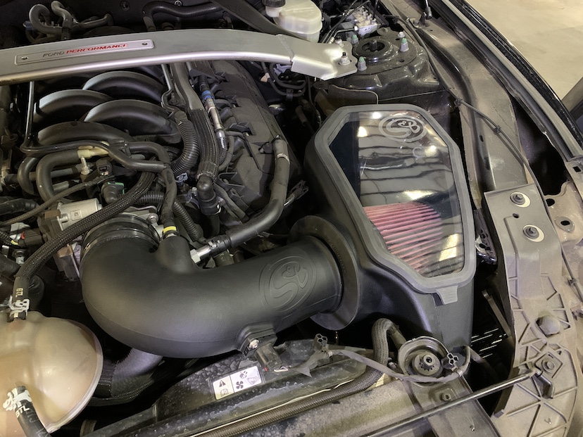
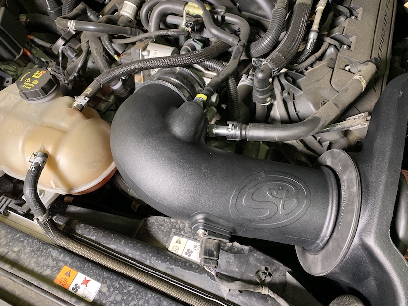
Install the S&B intake tube (12) into the vehicle in the position shown. Tighten the #64 hose clamp, securing the S&B intake tube to the engine throttle body.
Connect the vacuum hose to the S&B intake tube, pressing it onto the ¼ NPT quick connect.
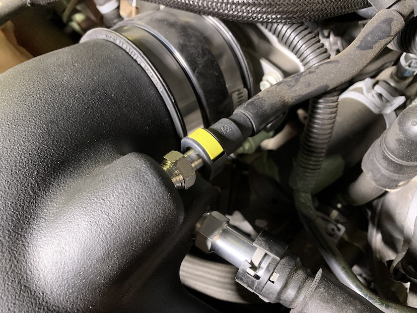
Connect the PCV hose to the S&B intake tube, pressing it onto the ⅜ NPT quick connect.
Reconnect the MAF sensor harness to the MAF sensor by pressing forward on the red locking tab.
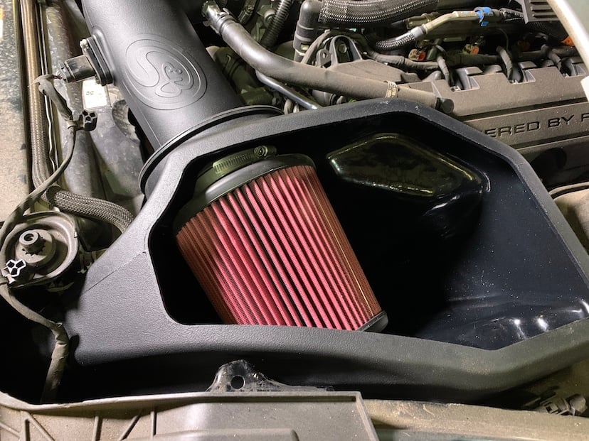
Connect the filter (10) to the S&B intake tube by placing it inside of the airbox and sliding the flange over the end of the tube. Secure the filter to the tube by tightening the #80 hose clamp (16).
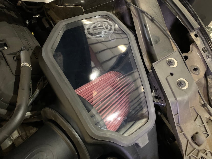
Install the lid seal (9) onto the lid (15) by stretching it around the perimeter of the lid. Snap the lid onto the top of the airbox by pressing down on all of the edges, ensuring that all edges of the lid are securely and completely snapped into place.
Reconnect the negative terminal on the battery.
Replace the battery cover by reinstalling the twisting panel screws.
Inspect your installation, make sure the kit is properly positioned and all fasteners are secured. S&B Filters recommends keeping all stock parts in case you would ever need to reinstall the stock intake. Affix the ID label near the intake kit. The installation is now complete.