STEP 1
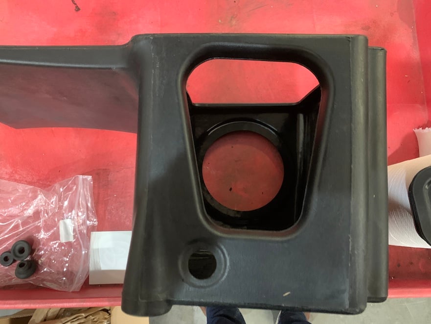
Remove the bolt and washer from the stock intake scoop. Then remove the scoop from the vehicle.
Tool Needed: 8mm Wrench or Socket.
Please read the entire product guide before proceeding. Ensure all components are present. If you are missing any of the components, call our customer support at (909) 947-0015. Do not work on your vehicle while the engine is hot. Make sure the engine is turned off and the vehicle is in Park or the Parking Brake is set.
Note: This intake kit may not fit with the following Aftermarket Parts installed: Body Lift, Custom Hood, Turbo Upgrade, Intercooler Upgrades.
8mm, 10mm, 11mm, 14mm Wrench or Socket, 5/16” Nut Driver or Flat Blade Screwdriver, ¼” Square Drive
Note: Approximate Install Time: 1 Hr 00 Mins.

Remove the bolt and washer from the stock intake scoop. Then remove the scoop from the vehicle.
Tool Needed: 8mm Wrench or Socket.

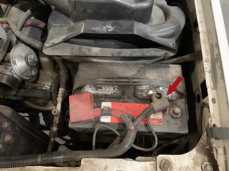
With the ignition switched off and the parking brake set, disconnect the negative battery cable on the drivers side.
Note: Failure to disconnect the battery may cause the CEL to illuminate upon completion of the installation and subsequent operation. Do not skip this step!
Tool Needed: 14mm Wrench or Socket.
Loosen the hose clamp at the baffle.
Tool Needed: 5/16” Nut Driver or 8mm Wrench or Socket.

Remove the 2 fasteners on the stock airbox lid.
Tool Needed: Flat head screwdriver or ¼” square drive depending upon OEM equipment.

Remove the stock airbox lid and tube, then remove the stock air filter.

Remove the stock airbox mounting nut and washer.
Tool Needed: 11mm Wrench or Socket.

Disconnect the electrical harness at the IAT sensor on the side of the stock airbox.
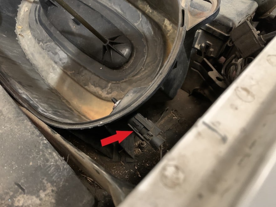
Pull up to remove the stock airbox.
Make sure to remove the grommets from the vehicle as well.

Remove the IAT sensor from the side of the stock airbox, the sensor uses a quarter turn locking pattern.

Determine which type of IAT sensor you have.

If your stock sensor looks like Type ‘A’, you will need to install the Grommet (M) into the side of the S&B Airbox (A)

If your stock sensor looks like Type ‘B’, leave the hole empty and proceed to step 12B.

Install the IAT sensor into the side of the S&B Airbox (A), if the sensor is Type ‘A’, push it through the Grommet (M).

If the sensor is Type ‘B’, unscrew the sensor’s ¼ turn adapter nut, place the sensor in the hole in the Airbox (A) and secure using the ¼ turn adapter nut.

Determine if you want to install the Box Plug (F) onto the Airbox (A) or leave it open. See the “Air Box Plug” note on Page 2 for more information. If the Box Plug (F) is desired, simply press the Box Plug (F) into the box opening until it snaps into place.

Install the other two Grommets (N) onto the S&B Airbox (A).

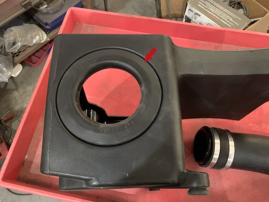
Install the Tube Seal (B) onto the Airbox (A).
Install the grommet to the airbox mounting bracket then install the bracket to the airbox.
.png?v=1721404427015)
Slide the Coupler (E) and loose Hose Clamps (J) onto the Intake Tube (D) until the end of the Coupler (E) meets up with the end of the Intake Tube (D).

Push the Intake Tube (D) through the Tube Seal (B) until the stop bead meets up with the Tube Seal (B).

Install the Air Filter (C) loosely onto the Intake Tube (D).

Place the assembly in the engine bay, reconnect the electrical harness at the IAT sensor.

Reconnect the negative battery cable.
Tool Needed: 14mm Wrench or Socket

Align the Airbox Grommets with the engine bay prongs and push down on the assembly until the engine bay prongs are fully seated in the two Grommets (M).

Slide the Coupler (E) onto the baffle and tighten both Hose Clamps (J).
Tool Needed: 5/16” Nut Driver or 8mm Wrench or Socket.

Tighten the hose clamp on the air filter (I).
Tool Needed: 5/16” Nut Driver or 8mm Wrench or Socket.

Secure the scoop to the vehicle using the M6 Bolt (K) and M6 Washer (L).
Tool Needed: 10mm Wrench or Socket

Remove the protective covering from the Clear Lid (H).
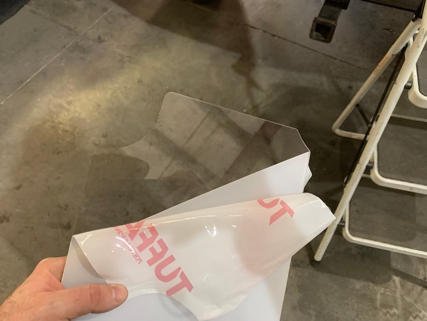
Install the Clear Lid (H) into the Snap-In Lid Seal (G).

Press the lid assembly into the box opening until it snaps into place. Inspect your installation, make sure the kit is properly positioned and all fasteners are secured. Keep all stock parts in case you would ever need to reinstall the stock intake assembly. Affix the ID label near the intake kit.
The installation is now complete.
